Isoda & Matuzaki
Mathematical Modeling in the Inquiry of Linkages Using LEGO and Graphic Calculator. Does New Technology Alternate Old Technology? ISODA Masami Institute of Education, University of Tsukuba
[email protected] MATSUZAKI Akio Graduate School of Education, University of Tsukuba
[email protected]
Abstract This study discussed the roles of old technology and new technology in the teaching of mathematical modeling. In this paper, a crank mechanism made of LEGO was used for teaching mathematical modeling. This paper, as the third phase of the research (Isoda, Matuzaki, Nakajima, 1998), discussed the changing roles of LEGO and a Graphic Calculator if we added the activity of making linkage (Matuzaki, 1999). From the case study, this paper distinguished the four cognitive phases through mathematical modeling: reasoning with the visual image in real world, reasoning with the mechanical structure, reasoning with the mathematical model without the mechanical structure and reasoning with the mathematical model and the mechanical structure. With comparing our results with Rose Mary Zbiek’s research (1998) which discussed the role of new technology in formulation of the model, this research discussed following: the real world activity should be distinguished before and after knowing the mechanical structure, and the mathematical activity with the model should be distinguished before and after synchronizing the parameters of the model and the parts of the mechanics. In this paper, graphic calculator as a piece of new technology helped mathematical works in the process of the mathematical modeling and LEGO as a piece of old technology helped the activity in real world. The synchronization of the model with the mechanics was supported by both technologies.
ATCM99
1 Introduction The innovative use of new technology has influenced education. In mathematics education Computer Algebra System, Graphing Tools and Dynamic Geometry Software (DGS) have influenced high school curriculums. Many kinds of alternative teaching programs have been developed in the US. In addition, the Internet has been changing the idea of mathematics teaching. From the perspective of Marshall McLuhan’s Media Revolution (1962) with the well known example of the printing technology of Gutenberg in the 15th century, the changing media from manuscript to type printing influenced the Scientific Revolution and we could not avoid the Media Revolution like medieval could not [1]. But does new technology alternate old technology? For example if we use DGS in geometry, can we discard a ruler and a compass? Of course we cannot, but we have to consider how the roles of a ruler and a compass should be changed. Descartes changed their roles from exclusive mathematical tool for geometry to one of mechanical tools which was used for representing mathematics. His view enhanced exploration of mechanics and influenced the technological and mechanical sciences and cognition. This paper explores the roles of old technology and new technology in the research context of mathematical modeling: a process described by Tatsuro Miwa (1983) as Formulation of Model, Mathematical Works Based on Model and Interpretation of Result [2]. Rose Mary Zbiek (1998) discussed the relation between new technology and prospective teachers’ strategies for mathematical modeling [3]. In this paper, we focus on mechanics in order to explore the changing role of old technology in the context of mathematical modeling and show an example of modeling by students. Our results will be compared with Zbiek’s research and the roles of old and new technologies will be clarified.
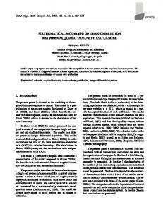
2 Mechanics and the Mathematical Model Mechanics has been developed along with mathematics. Before ENIAC, mathematicians tried to design physical mechanics for the calculation of calculus [4]. 20 years ago, some kinds of mechanics like figure 1 and 2 still have roles as mathematical instruments and we could find many kinds of the catalogs of mathematical instruments for classroom use [5]. Some of them were made by plastic, newest material but now in Japan, such instruments have been alternated computers. It is difficult to find such catalogs and instruments in classroom. Maria G. Bartolini Bussi discussed the historical instruments for using it in today’s classroom [6]. Following, the diversity of the mathematical model of mechanics are analyzed in order to show how its nature should be discussed . 2.1 Mechanics Designed by Geometric, Algebraic or Analytic Structure Until the 17th century, mechanics like those in figure 1 and 2 were usually developed using the representation of Geometry. On the other hand, since the beginning of the development of algebra in West Asia, algebra has been connected with geometry. After Descartes, D’Alembert designed the theoretical machine which could draw the graph of
Isoda & Matuzaki any polynomial function [6][7]. A physical copy of it made by Jean M. Laborde, Cabri group in Grenoble, only worked lower degree by physical problem. But we know that the virtural copy by DGS enable to work. We could see another physical copy by Franco Conti [8]. Herman H. Goldstine distinguished between the arithmetical-digital type machine like abacus and continuous-measuring-analogue type machine like planimeter [5]. Analogue type one is represented by Algebra or Analysis. Today, in the age of mechatoronics, analogue mechanics is controlled by digital computer.
Fig. 1 Descartes (1637)
Fig. 2 M. Bion (1709)
2.2 Parts Used in Mechanics and Parameters for Using Mechanics All Mechanics have a mechanical structure which could be also represented in mathematically. In the case of the pantograph, like figure 2, similarity is kept by the geometric structure which is based on the parallelogram and the line through the fulcrum, the force point and the influence point. If students know the structure of the pantograph, they must change the ratio of similarity as parameters. If not, they could explore the pantograph by changing parts and discover the conditions which keep the similarity. Cognitive structures must be strictly difference before and after knowing the structure. Before knowing the structure they enjoyed changing parts but after knowing the structure there were parameters which should be changed. In the case of D’Alembert’s machine, we can manipulate the parameters of the coefficients in the polynomial without knowing the hidden mechanical structure which might be represented by the geometric structure. We should also know that same mechanics can be manipulated according to one’s intuitions which depends upon user’s knowledge of mathematics. And we should not forget that mechanics helps to develop mathematics. For example, Descartes’ intuition about curves could not easily sheared with us without using his instruments which are also represented by DGS [7]. 2.3 Diversity of the Mathematical Model in the Kinematics Context The mathematical model of mechanics is not restricted to one structure in the kinematics context. For example, geometric representation can describe the motion of mechanics as locus but DGS shows its motion. Analytic (functional) representation can describe the changing of acceleration. Even if we set the context for mechanics, we can select many kinds of mathematical representations. In some cases, geometric representations fit the real situations better than algebraic representations. In other cases, algebraic
ATCM99 representations are preferable. Against such diversity, we should also consider the feature that the mathematical model of mechanics usually explains its own kinematics as a theoretically causal relation. In the case of the social sciences and some parts of engineering, we can discuss the mathematical model only by selecting the fittest function which correspond to the data but cannot explain the meaning of the functional representation as a theoretically causal relation. Thus, mechanics are preferred for teaching mathematical modeling.
3 A Case Study in a Secondary Classroom In order to explore the changing role of old technology in the context of mathematical modeling, we selected a crank mechanism and taught mathematical modeling to high school students for four hours [9]. The mathematical modeling problem was the same as in our previous research [10] but the making mechanics with LEGO was added in order to focus on the changing of the role. Nine female eleventh grade students who had never studied a crank before were selected. For collaborative exploration and for taking data of their communication, students were divided in groups which have two or three students in each. During class, students’ activities were recorded and student’s worksheets were gathered for qualitative analysis. Students had studied trigonometric functions previously but they needed help to formulate an equation for the mathematical model. 3.1 Mechanics Embedded in a Daily Context The session began with the question, “How does the wooden-horse of merry-go-round move?” Students engaged the question for two hours in the context of making marry-goround.
Fig. 3 (by students)
Fig. 4 (by students)
Fig. 5 (by students and teacher)
Most students answered from their experience that the motion was only up-and-down and the structure of the merry-go-round was unknown. Then, they watched the motion of wooden-horse on a video and were asked the same question once again. They answered that the up-and-down motion was provided by some mechanical structure similar to that of figure 3. The teacher, Akio Matuzaki, explained that a mechanical structure of crank hidden in merry-go-round but they feel strange and do not understand how the circle motion produces an up-and-down motion. This conflict was a result of the difference between the wooden-horse’s up-and-down motion on the turntable of marry-go-round
Isoda & Matuzaki which students had experienced while riding and the circle motion which also included the backward and forward motion. This result implies that students do not always have an appropriate image concerning the motion of mechanics even if they experience the motion frequently in daily life. 3.2 The Structure of Mechanics Beyond Visualized Materials In order to confirm the motion, teacher asked students to make the mechanics by LEGO which could represent the motion of wooden-horse. The teacher expected that students would make a mechanics using a crank but this task was difficult for students. For example, one group began by constructing the wooden-horse itself (figure 4) but then couldn’t reproduce the mechanism, they could construct only the separate parts. This result implies that students were reasoning with visual material but could not reasoning with the structure of mechanics. All groups tried to make but failed. Then the teacher gave students an incomplete sample to complete. The mechanism made by students represented the piston crank mechanism (figure 5) but many students imaged that the locus of wooden-horse must be circle (e.g. like enlargements of figure 6). This result implies that students were still reasoning using their visual images and could not reason using the mechanical structure even if they made the mechanics.
Fig. 6 Enlargement/No Crank
Fig. 7 Crank Motion
Fig. 8 Oval
3.3 Conflict between Students’ Visual Image and the Locus by the Mechanics In order to confirm the motion is circle or not, students drew loci like figure 7 using the crank (figure 5) by adding the pencil lead to the hole of LEGO rod. Contradictory to many students’ images, the loci were not circles (figure 9). Some students thought the loci were not drawn correctly because their hands moved when they were drawing, hence the circle did not appear as they supposed it would. This upset cognition implies that these students did not recognize the crank as an appropriate model for the wooden-horse motion and still did not reason with the mechanical structure. Many students discussed how the motion might be related with the structure as follows. 2182YM: The horse isn’t round on the upper side. 2183TT: Why can’t the horse connect with the upper side? 2185YM: Because? 2186TT: It could be round on the upper side. What do you think? Bottom Upper 2187NY: I agree. 2188YM: Why? Fig.9
ATCM99 The cogwheel is coiled around the horse! 2189All: Right! It’s funny (laughing). In the descriptions on the worksheet, students wrote the following, “I wonder that upper side is circle, but bottom side is a pressed oval (figure 8) and the height is same (figure 9). The locus is an elliptic or a semicircle (!?).” Two hours approach to the first question, students overcame their misunderstandings resulting from the visual images and became accustomed to the mechanical structure. We would like to note that almost all these activities were conducted as real world activities and that a few students can explain their finding about the mechanical structure with mathematical representations. 3.4 Formation of the Mathematical Model and Interpretations During the 3rd hour class, students were asked to represent mathematically the up-anddown motion of the crank’s piston (figure 10), endpoint, as an extreme case of the locus as the pressed ovals (figure 8 & 9). Students were allowed to use the LEGO crank and graphic calculator but all of them did not.
Fig. 10 The Piston Motion of Crank
Fig. 11 The Graph of the Function
Students couldn’t solve the problem by the paper and pencil approach. The teacher helped them to solve the problem theoretically and then they derived the equation of the function f ( ) = OA = rcos + L2 − 4sin2 as the mathematical model (the mathematical structure). In order to explore the meaning of this model, teacher asked students to measure the radius r and the arm L of figure 5, in this case, r = 2cm and L = 8cm. Next, the teacher asked students to explore the meaning of the function with graphic calculator. Students compared the up-and-down motion of the piston via the LEGO crank with the graph of the function (figure 11). Students wrote in their worksheet how the graph was related with the motion, “If the piston moves up, the cogwheel rotate right. And if the piston moves down, bar moves also down.” Through these interpretations students could interpret the mathematical model, mathematical structure, of motion with the crank motion. They could discuss that they enable to connect the up-and-down feeling on merry-go-round with the mathematical structure. It appears as if the new technology helped students to understand the structure of old technology. Even so, the teacher discovered in the next session that at this understanding was still weak. 3.5 The Parts of the Mechanics and the Parameters of the Mathematical Structure
Isoda & Matuzaki The 4th hour class was started from the mathematical structure, and compared the mathematical structure with the mechanical structure. The teacher asked students to explore the mathematical model with graphic calculator through making a lot of problems via changing the parameters of function. Each student made three or four problems, most of the problems were related to the ratio of r to L. Problems can be classified as follows: 1) r < L, 2) r = L, 3) r > L. Graphs of each case were shown on the following figure 12. Ratio
1) e.g. r : L = 1 : 3
2) e.g. r : L = 1 : 1
3) e.g. r : L = 3 : 1
Graphs Fig. 12 Students easily understood the case of 1) because this result is similar to the original ratio of the figure 11. But they couldn’t understand the case of 2) and 3) because they could not interpret the meaning of non-continuous graphs as follows. 4112TM: I don’t understand. 4113TT: Let’s try to demonstrait with LEGO. What do you think about the meaning of r = 2cm and L = 2cm in the mechanism? 4114TM: (laughing) 4115TT: Let’s think this problem together, MR. 4116TT: What does r = 2cm and L = 2cm mean in the mechanism? 4117MR: Aha, both lengths are equal. This protocol implies that students couldn’t easily to interpret the mechanical structure from mathematical structure. During the 3rd hour class, students were able to interpret the graph from the motion of the mechanics and this 4th hour, they were able to change the parameters of the mathematical structure. But for students, changing the parameters did not mean changing the parts of mechanics which corresponded to the changing parameters. In this case the mathematical model meant the each function and the result of mathematical work by graphic calculator meant the each graph. Students couldn’t interpret the mathematical results by new technology into the real world situations. Students reassembled the crank to the specified lengths of r and L are 2cm (figure 13). Then they confirmed the phenomenon of the non-continuous graph on the context of making mechanics. Students described on their worksheets. “If we apply the conditions of 2) or 3) to the wooden-horse will hit the cogwheel. These conditions are not appropriate for the crank mechanism. The length of L should be longer than of r for the crank (?)” This result implies that students understand that these linkages can not work as mechanism. Especially, the following protocol implies that students were able to realize that these
ATCM99 linkages are inappropriate mechanics. 4121TT: (Using LEGO of figure 11) The problem in this condition means this assembly, doesn’t it? What do you think about this linkage? What if we rotate the cogwheel …. 4122MR: Rotate? 4123TM: In this condition? 4124TT: TM, you made. 4125TM and MR: What is a strange ! (laughing) 4126TT: Write your findings on the sheet. 4127TM: In this condition, I can’t draw the graph. Fig. 13 r : L = 1 : 1 We should note here that by finding the linkages that could not be assembled as the mechanism, the students could relate the parameters on mathematical structure and the parts of the mechanical structure. Hence, the students were able to translate the parameters of the mathematical structure as visualized on the graph into the parts of the mechanical structure with LEGO. They were able to substantially connect the mathematical structure with the mechanical structure.
4 Discussion; the Role of Technology in Mathematical Modeling Now, we discuss the question, “Does new technology alternate old technology in the case of mathematical modeling?” First, we need to know that how new technology helps mathematical modeling. Rose Mary Zbiek found that, in the case of prospective teachers, four strategies can be used to develop and validate functions as mathematical models with computers [3]. The first strategy is Fitted-Function Selector which is a way of finding the fittest function for the data based on a goodness-of-fit value. And the other strategies are called Potential function, Scatter Plot/Graphing and Unneeded/Unused. From Zbiek’s discussion, we could know that technology helps the process of the formulation of mathematical model but in any strategies, prospective teachers were not success to get better interpretation between the mathematical model and the real world situations. Thus, if we alternate the formulation process with new technology, we will meet the crisis to lose the chance to connect between the mathematical model and the real world situation. But how can we help to connect the mathematical model and the situation. Our case study implies us the cognitive task which we need to overcome for lost connection. It shows that there are cognitive phases that needed to occur in connection between the mathematical model and the mechanics and that were originally discussed by Masami Isoda in 1993. Cognitive Phase 1: Reasoning with Visual Image Based on One’s Experience If students have images based on their experience in the real world, the images are usually too far from the cognitive structure to formulate the mathematical model.
Isoda & Matuzaki Cognitive Phase 2: Reasoning with the (Non Mathematical) Structure Students can over come misunderstanding through reasoning with the structure which will connect mathematical modeling. But they do not yet know the mathematical representation of it, they can reason with the structure and visual image, but they can not reason mathematically. Cognitive Phase 3: Reasoning with the Mathematical Model without the Structure. After the formulation of mathematical model as the mathematical structure of the structure in the real world, students are able to reason mathematically. But they still cannot compare the results with the structures in the real world if we change the parameters of the mathematical model. Cognitive Phase 4: Reasoning with the Mathematical Model and the Structure. Students become accustomed to the correspondence between the parameters of the mathematical model and the parts of the structure in real world. Theoretically, these phases must be mutually related and not restricted this order. In this case, the transitions were done by this order. In the transition from cognitive phase 1 to 2, the teacher set the making activity with old technology for focusing on the mechanical structure from the non-distinctive visual images. In the transition from phase 2 to 3, the teacher helped the formation of function from the structure and connected the model via the graphic representation, new technology, with the motion of mechanics. In the transition from phase 3 to 4, the teacher asked students to change parameters using the new technology and compare the results with the mechanical structure using the old technology. These transitions of phases will continue recursively in mathematical modeling. We know that the new technology alternates many parts of mathematical-algorithmic work in the process of mathematical modeling and enable to visualize the result. Human reasoning enables us to formulate the model and interpret the result. Zbiek, who focused on the formulation strategy, reported that very few students could overcome only selecting undesirable strategy, Fitted-Function Selector [3]. The real world activity was out of Zbiek’s research setting but she also discussed the importance of the understanding of the real world situation as same as the reliance on tool, the relative roles of mathematics and the frequency of tool use. The difference between phases 1 and 2 shows that students are living in the real world but their images of the situation are usually far from the structure needed for mathematical modeling. If students do not have appropriate images in the real world, they could not formulate the mathematical model and could not determine appropriate or not. In our example, linkage of mechanics as an old technology has a role to transit from phase 1 to 2. Our study also shows that two cognitive phases 3 and 4 should be distinguish in the interpretation. Linkage enables one to change the structure by changing parts. Changing both the parameter in the mathematical model and the parts of the mechanics enables one to synchronize between the real world and the mathematical model.
5 Result
ATCM99 As stated in the introduction, new technology, computer, do not alternate old technology but also change the role of old technology. Before the computer, mathematicians or engineers tried to synchronize their mathematical theory with mechanics. Since the computer, we can say that users of mathematics try to synchronize their work on the computer with structures of the real world, in some cases mechanical structures. The four cognitive phases themselves must not be changed before and since the computer. It implies that the recognition of the real world structure and the variability of the structure are important for synchronization. As computer tools used as new technologies take part in the mathematical work, linkage mechanics made of LEGO as an example of old technology take part in the recognition and variability of structure in the real world. The case study shows that the importance of the synchronization between the mechanical structure and the mathematical structure, old technology and new technology.
Reference [1] M. McLuhan. The Gutenberg Galaxy, The Making of Typographic Man. University of Toronto Press, Toronto, 1962. [2] Miwa Tatsuro. Mathematical Modeling in School Mathematics. Tadasu Kawagutchi etal. edited. Proceedings of ICMI-JSME Regional Conference on Mathematical Education. Japan Sociaty of Mathematics Education. WG-ß-7. 1983 [3] Rose Mary Zbiek, Prospective Teahcer’s Use of Computing Tools to Develop and Validate Functions as Mathematical Models, Journal of Reserch in Mathematics Education, vol.29,2,184-201, 1998 [4] H. H. Goldstine. The Computer, from Pascal to von Neuman. Princeton University Press, New Jersey, 1972. [5] W. Gellert etal. Kline Enzyklopadie Mathematik. VBE Bibiliographishes Institut Leipzig, 1975. [6] Maria G. Bartolini Bussi. Investigations of Instruments. (to appear) http://www.museo.unimo.it/theatrum/ [7] Masami Isoda. Developing the Curriculum for Curves Using History and Technology. Wei-Chi Yang etal. edited. Proceedings of the Third Asian Technology Conference in Mathematics. Springer. 82-89. 1998. [8] http://www.sns.it/html/OltreIlCompasso/Mostra-Matematica/mostra/macchina.htm [9] Akio Matuzaki, A Study of Integrated Learning between Mathematics and Other Subjects with Mathematical Modeling, Master Thesis, University of Tsukuba, 1999. [10] Masami Isoda, Akio Matuzaki, Masayoshi Nakajima. Mathematics Inquiry Enhanced by Harmonized Approach via Technology, A crank mechanism represented by LEGO and graphing tools. Edted by H. Park, Y. Choe, H. Shin and S Kim, Proceedings of the ICMI-EARCME, Korea Society of Mathematical Education. vol.3, 267-287. 1998