1 A Generic Environment for COTS Testing and ... - Semantic Scholar
Recommend Documents
2 Generic Programming. Generic programming [7,8,1,6] is based on a universal tree representation of datatypes. Whenever required, elements of any datatype ...
include word processors, email packages, etc [3]. ... customized (aka tailored) as needed in order to reduce ...... Second template gives guidance to acquire.
are pieces of software that can be reused by software projects ... Performing a good COTS selection plays a critical ...... risks (e.g. related to customer support). 3.
because the source code for the components involved isn't .... transfers them to an application server (IBM's. Websphere, in ... the component and monitoring its execution .... Table 1. Some approaches and tools for predicting performance for COTS-ba
language-style interpreter that executes a testing script. The interpreter was extended with intrinsic functions that call GPIB libraries, also built into the daemon.
restrictions on payment methods should as much as possible be banned. ... electronic commerce software fall short of such requirements. ... work ow for scheduling and synchronizing the various steps of complex processes, e.g. delivery of ...
electronic cash but only credit card, the Banker rst accepts payment from the Customer in .... Figure 4: The signatures of the operations of the CLF protocol.
Electronic mail may be sent to [email protected]. ..... In the figure, the syntax href="B_word_file#id(B1)" is a link to the word element with the id "B1" in ...
Jun 30, 2009 - and for didactic purposes using low cost COTS appliances and simple .... for the video servers, because a video server is necessary for each modality to ..... mercial provider and illuminated them with dedicated appli- ances.
Commercial off-the-shelf (COTS) software component is developed by a commercial vendor and is sold âas isâ. There is no single, accepted definition for a ...
User effort expended in customising software will be proportional to the perceived benefit of a product in achieving a job of work or entertainment. This implies ...
software engineering based on COTS software packages, the limitations of current ... a trade-off between the satisfaction of stakeholder requirements and architecture .... One advantage of a diagnostic approach is that it avoids the need for complete
This short paper presents a new research agenda to address problems of COTS software selection in the forthcoming decade. It describes the increasing shift ...
May 27, 2009 - En2. Factory Model M2. Ex2. Bounded. Proceedings of the 20th Workshop on Principles of Advanced and Distributed Simulation (PADS'06).
TOWARD A GENERIC ARCHITECTURE FOR MULTISOURCE INFORMATION FUSION. John R. Josephson and B. Chandrasekaran. Ohio State University.
Aug 24, 2005 - problems (e.g., incidence matrix and list representations for graphs), ... The 1968 NATO Conference on Software Engineering popularized the terms âsoftware ..... The design for generics in G is most closely related to type classes in
Commercial-off-the-Shelf (COTS) tools as software components ... Despite these advantages, developers encounter major obstacles ... There are many advantages in doing so. As a result .... disadvantage that COTS components may undergo.
slave Wishbone bus interface to the mailbox. So, the video processing hardware with mailbox can be connected easily to any on-chip bus in the SoC of the user ...
ment of generic mathematical libraries based on functors (parameterized modules) that have ... Both C++ and SML do not provide means for the speci cation of a.
statistical testing we consider has been inspired by the work of Thevenod-Fosse and ... and Van Cutsem [13] have widely generalized and system- atized the ... quality, and in Section 5 we discuss the issue of deriving test inputs, once a set ..... el
The paper addresses the definition of an ontology for cloud monitoring activities, with the aim of defining a .... Private cloud platforms may live without a struc-.
novel program execution model with three main features: (1) jobs are divided into a ...... entire automotive program group of MiBench (6 benchmarks) to evaluate the broader ..... [27] University of Michigan at Ann Arbor. MiBench Version 1.0 ...
Practical use of the contamination technique in stress testing for risk mea- sures Value at Risk (VaR) and Conditional Value at Risk (CVaR) and for op- timization ...
off-the-shelf (COTS) hardware and software components. However, the ... specific COTS software component, the operating system kernel. As an interface ...
1 A Generic Environment for COTS Testing and ... - Semantic Scholar
off-the-shelf components (COTS) as building bricks [2]. It is different from the traditional approach in which software systems are implemented from scratch.
1 A Generic Environment for COTS Testing and Quality Prediction Xia Cai1 , Michael R. Lyu1 , and Kam-Fai Wong2 Dept. of Computer Science and Engineering1 ,Dept. of Computer Science and Engineering2 ,The Chinese University of Hong Kong,Shatin, N.T., Hong Kong, China
{xcai,lyu}@cse.cuhk.edu.hk,[email protected] Summary. In this chapter, we first survey current component technologies and discuss the features they inherit. Quality assurance (QA) characteristics of component systems, and the life cycle of component-based software development (CBSD) are also addressed. Based on the characteristics of the life cycle, we propose a QA model for CBSD. The model covers the eight main processes in component-based software systems (CBS) development. A Component-based Program Analysis and Reliability Evaluation (ComPARE) environment is established for evaluation and prediction of quality of components. ComPARE provides a systematic procedure for predicting the quality of software components and assessing the reliability of the final system developed using CBSD. Using different quality prediction techniques, ComPARE has been applied to a number of component-based programs. The prediction results and the effectiveness of the quality prediction models for CBSD were outlined in this paper.
1.1 Introduction Based on the component-based software development (CBSD) approach[1], software systems are developed using a well-defined software architecture and off-the-shelf components (COTS) as building bricks [2]. It is different from the traditional approach in which software systems are implemented from scratch. Commercial off-the-shelf (COTS) components are developed by different developers using different languages and different platforms [3]. Typically, COTS components are available from a component repository; users select the appropriate ones and integrate them to establish the target software system (see Figure1.1). In general, a component has three main features: 1) it is an independent and replaceable part of a system that fulfills a clear function; 2) it works in the context of a well-defined architecture; and 3) it communicates with
other components by its interfaces [4]. Current component technologies have been used to implement different software systems, such as object-oriented distributed component software [5] and Web-based enterprise applications [6]. The system architecture of a component-based software system is layered and modular [7, 8, 9], see Figure 2.
Fig. 1.2. System architecture of component-based software systems
The top application layer entails information systems designed for various applications. The second layer consists of components for a specific system or application domains. Components in this layer are applicable to more than one single application. The third layer comprises of cross-system middleware components which includes common software and interfaces to other estab-
1 A Generic Environment for COTS Testing and Quality Prediction
3
lished entities. The fourth layer of system software components includes basic components that interface with the underlying operating systems and hosting hardware. Finally, the lowest two layers involves the operating and hardware systems. A CBSD-based software system is composed of one or more components, which may be procured from off-the-shelf, produced in-house or developed by contracts. The overall quality of the final system depends heavily on the quality of the components involved. One needs to be able to assess the quality of a component to reduce the risk of development. Software metrics are designed to measure different attributes of a software system and the development process, and are used to evaluate the quality of the final product [10]. Process metrics (e.g., reliability estimates) [11], static code metrics (e.g., code complexity) [12] and dynamic metrics (e.g., test thoroughness) [13] are widely used to predict the quality of software components at different development phases [10, 14]. Several techniques are used to model the predictive relationship between different software metrics and for component classification, i.e., classifying software components into fault-prone and non fault-prone categories [15]. These techniques include discriminant analysis [16], classification trees [17], pattern recognition [18], Bayesian network [19], case-based reasoning (CBR) [20], and regression tree models [15]. There are also prototypes and tools [11, 21], which use such techniques to automate software quality prediction. However, these tools employ only one metric, e.g., process metrics or static code metrics. Furthermore, they rely on only one prediction technique for overall software quality assessment. The objective of this chapter is to evaluate individual quality of off-theshelf components and overall quality of software systems. We integrate different prediction techniques and different software metric categories to form a single environment, and investigate their effectivenss on quality prediction of components and CBS. The rest of this chapter is organized as follows: we first give an overview of the state-of-the-art CBSD techniques in Section 2, and highlight the quality assurance (QA) issues behind them in Section 3. Section 4 proposes a QA model which is designed for quality management in CBSD process. In Section 5, we propose ComPARE, a generic quality assessment environment for CBSD. It facilitates quality evaluation of individual components as well as the target systems. Different prediction models have been applied to real world CORBA programs. In Section 6, the pros and cons of these prediction models are analyzed. Finally, Section 7 concludes this chapter.
4
Xia Cai, Michael R. Lyu, and Kam-Fai Wong
1.2 A Development Framework for Component-Based Software Systems A framework can be defined as a set of constraints on components and their interactions, and a set of benefits that derive from those constraints [22]. To identify the development framework for component-based software, the framework or infrastructure for components should be identified first, as components are the basic units in the component-based software systems. Visual Basic Controls (VBX), ActiveX controls, class libraries, JavaBeans, etc., make it possible for their corresponding programming languages, i.e. Visual Basic, C++, Java, and the supporting tools to share and distribute application fragments. But all these approaches rely on certain underlying services to provide communication and coordination. The infrastructure of components (sometimes called a component model) acts as the ”plumbing” that allows communication among components [4]. Among the component infrastructure technologies that have been developed, there are three de facto industrial standards: OMG’s CORBA, Microsoft’s Component Object Model (COM) and Distributed COM (DCOM), and Sun’s JavaBeans and Enterprise JavaBeans [23]. 1.2.1 Common Object Request Broker Architecture (CORBA) CORBA is an open standard for interoperability. It is defined and supported by the Object Management Group (OMG), an organization of over 400 software vendor and object technology user companies [24]. CORBA manages details of component interoperability, and allows applications to communicate with one another despite of different locations and designs. Interface is the only way, which applications or components communicate. The most important part of a CORBA system is the Object Request Broker (ORB). ORB is the middleware that establishes client-server relationship between components. Using an ORB, a client can invoke a method on a server object, whose location is completely transparent. ORB is responsible for intercepting a call and finding an object, which can implement the request, pass its parameters, invoke its method, and return the results. The client does not need to know where the object is located, its programming language, its operating system, or any other system aspects, which are not related to the interface. In this way, ORB supports interoperability among applications on different machines in heterogeneous distributed environments and can seamlessly interconnect multiple object systems. CORBA is widely used in Object-Oriented distributed systems [5] including component-based software systems for it offers a consistent distributed programming and run-time environment over common programming languages, operating systems, and distributed networks.
1 A Generic Environment for COTS Testing and Quality Prediction
5
1.2.2 Component Object Model (COM) and Distributed COM (DCOM) Component Object Model (COM) is a general architecture for component software [25]. It supports platform-dependent, based on Windows and Windows NT, and language-independent component-based applications. COM defines how components and their clients interact. As such, a client and a component can be connected without the support of an intermediate system component. In particular, COM provides a binary standard, which components and their clients must follow to ensure dynamic interoperability. This enables on-line software update and cross-language software reuse [26]. Distributed COM (DCOM) is an extension of the Component Object Model (COM). It is a protocol that enables software components to communicate directly over a network in a reliable, secure, and efficient manner. DCOM supports multiple network protocols, including Internet protocols such as HTTP. When a client and its component reside on different machines, DCOM simply replaces the local interprocess communication with a network protocol. Neither the client nor the component is aware of changes in the physical connections. 1.2.3 Sun Microsystems’s JavaBeans and Enterprise JavaBeans Sun’s Java-based component model consists of two parts: the JavaBeans for client-side component development and the Enterprise JavaBeans (EJB) for the server-side component development. The JavaBeans component architecture supports multiple platforms, as well as reusable, client-side and serverside components [27]. Java platform offers an efficient solution to the portability and security problems through the use of portable Java bytecode and the concept of trusted and untrusted Java applets. Java provides a universal integration and enabling technology for enterprise application integration (EAI). The technology enables 1) interoperation across multivendor servers; 2) propagation of transaction and security contexts; 3) multilingual clients; and 4) supporting ActiveX via DCOM/CORBA bridges. JavaBeans and EJB extend the native strength of Java including portability and security to component-based development. The portability, security, and reliability nature of Java are well suited for developing robust server objects independent of operating systems, Web servers and database management servers. 1.2.4 Comparison among Different Architectures Comparison bwteen the development technologies for component-based software systems can be found in [4, 28, 29]. Table 1.1 summarizes their different features.
6
Xia Cai, Michael R. Lyu, and Kam-Fai Wong
Table 1.1. Comparison of development technologies for component-based software systems Development environment Binary interfacing standard Compatibility and portability Modification and maintenance Services provided
CORBA Underdeveloped
EJB Emerging
Not binary standards
Based on COM; Java specific
Particularly strong in standardizing language bindings; but not so portable CORBA IDL for defining component interfaces, need extra modification and maintenance A full set of standardized services; lack of implementations Platform independent
Portable by Java language specification; but not very compatible.
Platform dependency Language Language independent dependency Implementation Strongest for traditional enterprise computing
Platform independent
COM/DCOM Supported by a wide range of strong development environments A binary standard for component interaction is the heart of COM Not having any concept of source-level standard of standard language binding. Microsoft IDL for defining component interfaces, need extra modification and maintenance Recently supplemented by a number of key services Platform dependent
Language dependent
Language independent
Not involving IDL files, defining interfaces between component and container. Easier modification and maintenance. Neither standardized nor implemented
Strongest in general Web Strongest in traditional clients. desktop applications
1.3 Quality Assurance for Component-Based Software Systems 1.3.1 The Development Life Cycle of Component-Based Software Systems A component-based software system (CBS) is developed by assembling different components rather than programming from scratch. Thus the life cycle of a component-based software system is different from that of a traditional software system. The cycle can be summarized as follows [2]: 1) Requirements analysis; 2) Software architecture selection, construction, analysis, and evaluation; 3) Component identification and customization; 4) System integration; 4) System testing; 5) Software maintenance. The architecture of CBS defines a system in terms of computational components and interactions among components. The focus is on composing and assembling components. Composition and assembly mostly take place separately, and even independently. Component identification, customization and integration are crucial activities in the development life cycle of CBS. It includes two main parts: 1) evaluation of candidate COTS based on the functional and quality requirements provided by the user; and 2) customization of suitable candidate COTS prior to integration. Integration involves communication and coordination among the selected components. Quality assurance (QA) for CBS targets every stage of the development life cycle. QA technologies for CBS are currently premature as specific char-
1 A Generic Environment for COTS Testing and Quality Prediction
7
acteristics of component systems are not accounted for. Although some QA techniques such as reliability analysis model for distributed software systems [30, 31] and component-based approach to Software Engineering [32] have been studied, there is still no clear and well-defined standards or guidelines for CBS. The identification of the QA characteristics, along with the models, tools and metrics, are all under urgent needs. 1.3.2 Quality Characteristics of Components QA technologies for component-based software development has to cater for two inseparable parts: 1) How to ensure the quality of a component? 2) How to ensure the quality of the target component-based software system? To answer these questions, models should be defined for quality control of individual components and the target CBS; metrics should be defined to measure the size, complexity, reusability and reliability of individual components and the target CBS; and tools should be designed to evaluate existing components and CBS. To evaluate a component, we must determine how to assess the quality of the component [33, 34]. Here we propose a list of component features for the assessment: 1) Functionality; 2) Interface; 3) Usability; 4) Testability; 5) Maintainability; 6) Reliability. Software metrics can be proposed to measure software complexity [35, 36]. Such metrics are often used to classify components [37]. They include 1) Size. This affects both reuse cost and quality. If it is too small, the benefits will not exceed the cost of managing it. If it is too large, it is hard to ensure high quality. 2) Complexity. This also affects reuse cost and quality. A component which is too-trivial is not worthwhile to modularize. But on the other hand, a component which is too complex is hard to ensure high quality. 3) Reuse frequency. The number of times and different domains where a component has been used previously is a solid indicator of its usefulness. 4) Reliability. The probability of failure-free operations of a component under certain operational scenarios [38].
1.4 A Quality Assurance Model for Component-Based Software Systems Since component-based software systems are developed on an underlying process different from that of traditional software, their quality assurance model should address both the process of componentization and the process of the overall system development. Figure 1.3 illustrates this view. Many standards and guidelines are used to control the quality activities of traditional software development process, such as ISO9001 and CMM model
8
Xia Cai, Michael R. Lyu, and Kam-Fai Wong
Fig. 1.3. Quality assurance model for both components and systems
[39]. In particular, Hong Kong productivity Council has developed the HKSQA model to localize the general SQA models [40]. In this section, we propose a quality assurance model for component-based software development. In our model, the main practices relating to components and software systems contain the following phases: 1) Component requirement analysis; 2) Component development; 3) Component certification; 4) Component customization; 5) System architecture design; 6) System integration; 7) System testing; and 8) System maintenance. 1.4.1 Component Requirement Analysis Component requirement analysis is the process of discovering, understanding, documenting, validating and managing the requirements of a component. The objectives of component requirement analysis are to produce complete, consistent and relevant requirements, which a component should realize, as well as the programming language, platform and interfaces related to the component. Initiators (Users, Customers, Manager etc.) Request for new development or change Requirement Document Template
Format & Structure Current URD
Requirements Gathering and Definition Draft User Requirement Documentation (URD) Requirement Analysis Component Requirement Document (CRD)
Data Dictionary
Structure for naming & Describing
Component Modeling Updated CRD with model included
System Maintenance
Requirement Validation User Requirement Changes
Current URD
Component Development
Fig. 1.4. Component requirement analysis process overview
1 A Generic Environment for COTS Testing and Quality Prediction
9
The component requirement process overview diagram is as shown in Figure 1.4. Initiated by the users or customers for a new development or changes to an old system, component requirement analysis consists of four main steps: requirements gathering and definition, requirement analysis, component modeling, and requirement validation. The output of this phase is the current user requirement documentation, which should be transferred to the next component development phase, the user requirement changes for the system maintenance phase, and data dictionary for all the latter phases. 1.4.2 Component Development Component development is the process of implementing the requirements for a well-functional, high quality component with multiple interfaces. The objective of component development is the development of the final component products, their interfaces, and the corresponding development documents. Component development should lead to the final components satisfying the requirements with correct and expected results, well-defined behaviors, and flexible interfaces. Developers Techniques required
Component Requirement Document
Requirements
Existing Fault
Implementation Draft Component
Self-Testing (Function) Well-Functional Component
Self-Testing ( Reliability) Reliable Component
System Maintenance For Reference
Development Document
Submit
Component Certification
Fig. 1.5. Component development process overview
The component development process overview diagram is shown in Figure 1.5. Component development consists of four procedures: implementation, function testing, reliability testing, and development documentation. The input to this phase is the component requirement document. The output should be the developed component and its documents, ready for the following phases of component certification and system maintenance, respectively.
10
Xia Cai, Michael R. Lyu, and Kam-Fai Wong
1.4.3 Component Certification Component certification is the process, which involves: 1) component outsourcing: managing a component outsourcing contract and auditing the contractor performance; 2) component selection: selecting the right components in accordance to the requirements for both functionality and reliability; and 3) component testing: confirm that the component satisfies the requirement with acceptable quality and reliability. System Requirements Specific Component Requirements
Component Development Document
Component Functions Reject
Component Outsourcing Component Released
Component Testing Well-Functional Component
Component Selecting Component fit for the special requirements
Acceptance Contract Signoffs, Payments
System Maintenance
Fig. 1.6. Component certification process overview
The objectives of component certification are to outsource, select and test the candidate components and check whether they satisfy the system requirement with high quality and reliability. The governing policies are: 1) component outsourcing should be charged by a software contract manager; 2) all candidate components should be tested to be free from all known defects; and 3) testing should be in the target environment or in a simulated environment. The component certification process overview diagram is shown in Figure 1.6. The input to this phase is the component development documents, and the output is the testing documentation for system maintenance. 1.4.4 Component Customization Component customization is the process which involves 1) modifying the component for specific requirements; 2) making necessary changes to the component for running on the local platforms; 3) upgrading the specific component to get a better performance or a higher quality. The objective of component customization is to make necessary changes to a developed component so that it can be used in a specific environment or cooperate with other components well.
1 A Generic Environment for COTS Testing and Quality Prediction
11
System Requirements & Other Component Requirements Specific System & Other Component Requirements
Component Development Document
Component Document Reject
Component Customization Component Changed
Component Document New Component Document
Component Testing Component fit for the special requirements
System Integration
Acceptance Assemble
Component Document
System Maintenance on
Fig. 1.7. Component customization process overview
All components must be customized according to the operational system requirements or the interface requirements. The component customization process overview diagram is shown in Figure 1.7. The input to component customization are the system requirements, the component requirements, and component development documents. The output are the customized components, and documents for system integration and system maintenance. 1.4.5 System Architecture Design System architecture design is the process of evaluating, selecting and creating software architecture of a component-based software system. The objectives of system architecture design are to collect the users requirements, determine the system specification, select appropriate system architecture, and determine the implementation details such as platform, programming languages, etc. System architecture design should compare the pros and cons of different system architectures and select the one suitable for the target CBS. The process overview diagram is shown in Figure 1.8. This phase consists of system requirement gathering, analysis, system architecture design, and system specification. The output of this phase comprises of the system specification document for system integration, and the system requirements for the system testing and system maintenance phases. 1.4.6 System Integration System integration is the process of properly assembling the components selected to produce the target CBS under the designed system architecture. The process overview diagram is shown in Figure 1.9. The input are the system requirement documentation and the specific architecture. There are four steps
12
Xia Cai, Michael R. Lyu, and Kam-Fai Wong Initiators Requests for New Systems
Requirement Document Template
Format & Structure
System Requirement Gathering
Current Document
Draft System Requirements Document
System Requirement Analysis System Requirement Document
System Architecture Design
System Maintenance
System Architecure
System Testing
System Requirement
System Specification
System Specification Document
System Integration
Fig. 1.8. System architecture design process overview System Requirement Requirements for New Systems
System Architecture
Architecture
Current Component
System Integration Draft System
Self-Testing Fault Component
Component Changing
Component Requirement
Component Certification
Selecting New Component
System Testing
Final System
Final System
System Integration Document
System Maintenance
Fig. 1.9. System integration process overview
in this phase: integration, testing, changing component and re-integration (if necessary). At the end of this phase, the final target system will be ready for system testing, and the appropriate document for the system maintenance phase. 1.4.7 System Testing System testing is the process of evaluating a system to: 1) confirm that the system satisfies the specified requirements; 2) identify and correct defects. System testing includes function testing and reliability testing. The process overview diagram is shown in Figure 1.10. This phase consists of selecting testing strategy, system testing, user acceptance testing, and completion activities. The
1 A Generic Environment for COTS Testing and Quality Prediction
13
System Design Document System Maintenance (Previous Software Life Cycle)
System Integration
Testing Requirements Test Dependencies
System Test Spec.
Testing Strategy System Testing Plan Component Document System
Testing
Component Development
System Tested User Acceptance Test Spec. User Acceptance
Component Document
Testing User Accepted System
Test Completion Activities
System Integration Document
System Maintenance
Fig. 1.10. System testing process overview
input comprises of the documents from the component development and system integration phases. And the output includes the testing documentation for system maintenance. Note that this procedure must cater for the interaction testing between multiple components, which includes coordination issues, deadlocks, etc. 1.4.8 System Maintenance
Users Request and Problem Reports
All Previous Phases
Documents, Strategies
Support Strategy User Support Agreement
Problem Management Change Requests
System Maintenance
New Version
System Testing
Fig. 1.11. System maintenance process overview
System maintenance is the process of providing service and maintenance activities required to use the software effectively after it has been delivered. The objectives of system maintenance are to provide an effective product or service to the end-users while repairing faults, improving software performance or other attributes, and adapting the system to a changed environment.
14
Xia Cai, Michael R. Lyu, and Kam-Fai Wong
A maintenance organization should be available for every CBS product. All changes for the delivered system should be reflected in the related documents. The process overview diagram is shown in Figure 1.11. According to the outputs from all previous phases as well as requests and problem reports from users, system maintenance should be performed to determine the setup support and problem management (e.g., identification and approval) strategies. This phase produces a new version of the CBS, which may be subjected to further system testing.
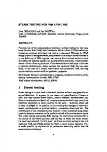
1.5 A Generic Quality Assessment Environment for Component-Based Systems - ComPARE We propose a Component-based Program Analysis and Reliability Evaluation (ComPARE) to evaluate the quality of software systems in componentbased software development. ComPARE automates the collection of different metrics, the selection of different prediction models, the formulation of userdefined models, and the validation of the established models according to faulty data collected in the development process. Different from other existing tools [21], ComPARE takes dynamic metrics into account (such as code coverage and performance metrics), integrates them with process metrics and other static code metrics (such as complexity metrics, coupling and cohesion metrics, inheritance metrics) which are adopted from object-oriented software engineering, and provides different estimation models for overall system assessment. 1.5.1 Overall Architecture A number of commercial tools are available for the measurement of software metrics for object-oriented programming. Also there are off-the-shelf tools for testing and debugging of software components [41]. However, few tools can measure the static and dynamic metrics of software systems, perform various quality modeling, and validate such models against actual quality data. ComPARE aims to provide an environment for quality prediction of software components and assess the reliability of the overall system based on them. The overall architecture of ComPARE is shown in Figure 1.12. First of all, various metrics are computed for the candidate components, then the users can select and weigh the metrics deemed important to quality assessment. After the models have been constructed and executed (e.g., ”case base” is used in BBN model), the users can validate the selected models with previous failure data collections. If the users are not satisfied with the prediction result, they can go back to the previous step, re-define the criteria and construct a revised model. Finally, the overall quality prediction can be displayed based on the architecture of the candidate system. Results from individual components can also be displayed for sensitivity analysis and system redesign.
1 A Generic Environment for COTS Testing and Quality Prediction
15
Case Base
Metrics Computation
Candidate Components
Criteria Selection
Model Definition
System Architecture
Model Validation
Result Display
Failure Data
Fig. 1.12. Architecture of ComPARE
The objectives of ComPARE are summarized as follows: 1. To predict the overall quality by using process metrics, static code metrics as well as dynamic metrics. In addition to complexity metrics, we use process metrics, cohesion metrics, inheritance metrics as well as dynamic metrics (such as code coverage and call graph metrics) as the input to the quality prediction models. Thus the prediction is more accurate as it is based on data from every aspect of the candidate software components. 2. To integrate several quality prediction models into one environment and compare the prediction result of different models. ComPARE integrates several existing quality models into one environment. In addition to selecting or defining these different models, the users can also compare the prediction results of the models on the candidate component and see how good the predictions are if the failure data of the particular component is available. 3. To define the quality prediction models interactively. In ComPARE, the user can select from several quality prediction models and select the one most suitable for this prediction task. Moreover, the user can also define their own models and validate them in the evaluation stage. 4. To classify components using different quality categories. Once the metrics are computed and the models selected, the overall quality of the component can be displayed according to the category it belongs to. Program modules with problems can also be identified. 5. To validate reliability models defined by the user against real failure data (e.g., change report). Using the validation criteria, the result of the selected quality prediction model can be compared with failure data in real life. The user can redefine their models according to the comparison. 6. To show the source code with potential problems at line-level granularity. ComPARE can identify the source code with high risk (i.e., the code that
16
Xia Cai, Michael R. Lyu, and Kam-Fai Wong
is not covered by test cases in the environment) at line-level granularity. This can help the users locate high risk program modules or portions promptly and conveniently. 7. To adopt commercial tools in accessing software data related to quality attributes. We adopt Metamata [42] and Jprobe [43] suites to measure the different metrics for the candidate components. These two tools, involving metrics, audits, debugging, as well as code coverage, memory and deadlock detected, are commercially available. 1.5.2 Metrics Used in ComPARE
Table 1.2. Process Metrics Metric Time Effort Change Report
Description Time spent from design to delivery (months) Total human resources used (man*month) Number of faults found in development
Three different categories of metrics, namely process, static, and dynamic, are analyzed in CompARE to give the overall quality prediction. We have chosen proven metrics, i.e., those that are widely adopted by previous software quality prediction tools in the software engineering research community [44, 45]. The process metrics we selected are listed in Table 1.2 [11]. Since we perceive that Object-Oriented (OO) techniques are essential in componentbased software development, we select static code metrics according to the most important features in OO programs, i.e., complexity, coupling, inheritance and cohesion. They are listed in Table 1.3 [12, 13, 42, 46]. The dynamic metrics measuring component features when they are executed. Table 1.4 shows the detailed description of the dynamic metrics. Sets of process, static, and dynamic metrics can be collected from commercial tools, e.g., Metamata Suite [42] and Jprobe Testing Suite [43]. We adopt these metrics in ComPARE. 1.5.3 Models Definition In order to predict the quality of software systems, several techniques have been developed to classify software components according to their reliability [15]. These techniques include discriminant analysis [16], classification trees [17], pattern recognition [18], Bayesian network [19], case-based reasoning (CBR) [20], and regression tree model [11]. Up to now, there is no good quality prediction models for CBS. Here we set some evaluation criteria for good quality prediction models [47]: 1)Useful quantities: the model can make predictions of quantities reflecting software
1 A Generic Environment for COTS Testing and Quality Prediction
Number of Attri-butes (NA) Number Of Classes (NOC)
Description Number of lines in the components including statements, blank lines, lines of commentary, and lines consisting only of syntax such as block delimiters. A measure of the control flow complexity of a method or constructor. It counts the number of branches in the body of the method, defined by the number of WHILE statements, IF statements, FOR statements, and CASE statements. Number of fields declared in the class or interface.
Number of classes or interfaces, which are declared. This is usually 1, but nested class declarations will increase this number. Depth of Inheritance Length of inheritance path between the current class and Tree (DIT) the base class. Depth of Interface The path between the current interface and the base inExtension Tree terface. (DIET) Data Abstraction Number of reference types, which are used in the field decCoupling (DAC) larations of the class or interface. Fan Out Number of reference types, which are used in field decla(FANOUT) rations, formal parameters, return types, throws declarations, and local variables. Coupling between Number of reference types, which are used in field declaObjects (CO) rations, formal parameters, return types, throws declarations, local variables and also types from which field and method selections are made. Method Calls Number of calls to/from a method. It helps analyze the Input/Output coupling between methods. (MCI/MCO) Lack of Cohesion For each pair of methods in the class, the set of fields each of Methods (LCOM) of them accesses is determined. If they have disjoint sets of field then increase the count P by one. If they share at least one field then increase Q by one. After considering each pair of methods, LCOM = (P − Q) =0
if
P >Q
otherwise
18
Xia Cai, Michael R. Lyu, and Kam-Fai Wong Table 1.4. Dynamic Metrics Metric
Test Case Coverage Call Graph metrics
Heap metrics
Description The coverage of the source code when the given test cases are executed. Statistics about a method, including method time (the amount of time the method spent in execution), method object count (the number of objects created during the method execution) and number of calls (how many times each method is called in you application). Number of live instances of a particular class/package, and the memory used by each live instance.
quality. 2)Prediction accuracy: the model can make predictions of quality which can be accurately observed later. 3)Ease of measuring parameters: the parameters in the model are easily measured or simulated. 4)Quality of assumptions: the assumptions should be reasonable, rather than too narrow or limited. 5)Applicability: the model should be widely used in various projects or experiments. 6)Simplicity: the model should not be too hard to implement or realize. In ComPARE, we combine existing quality prediction models according to the above criteria. Initially, one employs an existing prediction model, e.g., classification tree model or BBN model, customizes it and compares the prediction results with different tailor-made models. In particular, we have investigated the following prediction models and studied their applicability to ComPARE in our research. Summation Model This model gives a prediction by simply adding all the metrics selected and weighted by the user. The user can validate the result by real failure data, and then benchmark the result. Later when new components are included, the user can predict their quality according to their differences from the benchmarks. The concept of summation model is formulated as follows: Q=
n X
αi mi
(1.1)
i=1
where mi is the value of one particular metric, αi is its corresponding weighting factor, n is the number of metrics, and Q is the overall quality mark. Product Model Similar to the summation model, the product model multiplies all the metrics selected and weighted by the user. The resulting value indicates the level of
1 A Generic Environment for COTS Testing and Quality Prediction
19
quality of a given component. Similarly, the user can validate the result by real failure data, and then determine the benchmark for later usage. The concept of product model is shown as follows: Q=
n Y
mi
(1.2)
i=1
where mi is the value of one particular metric, n is the number of metrics, and Q is the overall quality mark. Note that mi ’s are normalized to a value close to 1, so that no single metric can dominate the result. Classification Tree Model