1
DESIGN AND DEVELOPMENT OF FIVE PARALLEL ENGINES FOR LUBRICANTS AND FUEL TESTING EXPERIMENTAL RIGS PART 1 M. Aliff Ashraf Automotive Engineering Research Group (AERG), Faculty of Mechanical Engineering, Universiti Malaysia Pahang, 26600 Pekan, Pahang, Malaysia, Automotive Engineering Centre, Universiti Malaysia Pahang (UMP), 26600 Pekan, Pahang, Malaysia, Phone: +60199581506 Email:
[email protected] ABSTRACT An engine test rig could serve for further analysis for researchers to study about the engine which it is depends on the type of applications needed. It is all depends on the properties and concept focused to be studied for researcher about the engines and how the surrounding factors could affect the rate. Therefore a mechanical design of five parallel engine arrangement for lubricant and fuel testing experimental test rig have been developed. The purpose of this experiment is to study the rate of wearying effects on engine components such as crankshaft, pistons, and piston valves. Same type of five grass cutter engines was used and it is arranged parallel in the test rig. In this test, the engines were run for few hours with the applied of a solid cylinder rod, which fixed to shaft connecting part of the engine as a load for this experiment. The rate of weariness, of each component of the engines is further analyzed based on the hours of engine run and the throttle turns that have been set up in the Arduino software through a computer. Keywords: parallel, weariness, engine components, Arduino, test rig. INTRODUCTION Heywood has mentioned that diesel cycle is a combustion process of a reciprocating internal combustion engine [1]. Noor and other authors said that in a combustion of engine process, three things steps or processes are required which is fuel itself, oxidizer and a heat or ignition source [2]. Devarajan and other authors has said that the fossil fuel such as diesel, petrol and natural gas are a non-renewable energy source which can affect to the world when it is come to finite amount in earth [3]. In the engine, fuel is ignited by heat generated during the compression of air in the combustion chamber of engine into which fuel is then injected [1]. Greenhouse effect, acid rain are developed as the amount of carbon dioxide is contributes to environment is in high rate due to the burning of fuel by internal combustion which releases pollutants in the air said by Devarajan and other authors [3]. This is a contrast to igniting the fuel-air mixture with a spark plug as in the Otto cycle engine. In terms of applications, diesel engines are widely used in aircraft, automobiles, power generation, diesel-electric locomotives, and both surface ships and submarines [1]. The diesel internal combustion engine differs from the gasoline powered. Eventually, Noor and other authors has investigated that the combustion of fuel produces less carbon dioxide and other chemical as the combustion of engine is one of main issue given important on environmental concerns and issues [4]. The large amount of fossil fuel which is about 80% is projected for the internal combustion as it is the most and important source of energy said by Noor and other authors [5]. Otto cycle by using a higher compression of the fuel to ignite the fuel rather
2
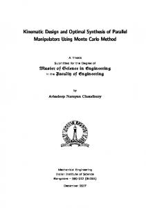
than using a spark plug which "compression ignition" rather than "spark ignition". Hotti and another author mentioned in the diesel engine, air is compressed adiabatically with a compression ratio typically 15 to 20 [6]. This compression raises the temperature to the ignition temperature of the fuel mixture which is formed by injecting fuel once the air is compressed [6]. According to the performance by Mon and other authors, the temperature distribution in engines are influenced by material used to construct the engine part near the exhaust port near the cylinder head [7]. The ideal air-standard cycle is modelled as a reversible adiabatic compression followed by a constant pressure combustion process, then an adiabatic expansion as a power stroke and an isovolumetric exhaust said by Cengal Yunus and other author [8]. Figure 1 shows the schematics diagram of single cylinder engine. The engine is running with single cylinder or piston for internal combustion. A single-cylinder engine is a basic piston engine configuration of an internal combustion engine. Rahman and other authors investigated the fatigue life prediction of a piston and on their performance said that a free piston linear generator of engine can integrates a combustion engine and linear electrical machine into a single unit without a crankshaft [9]. Some of the applications of single piston engine are often seen on motorcycles, auto rickshaws, motor scooters, mopeds, dirt bikes, go-karts, radio-controlled models, and has many uses in portable tools and garden machinery [10]. Wargante and another author has mentioned that a single-cylinder engines are simple and compact, and will often deliver the maximum power possible within a given envelope [10]. According to Pulkrabek cooling is simpler than with multiple cylinders, potentially saving further weight, especially if air cooling can be used [11]. Pulkrabek also mention that the single-cylinder engines require more flywheel effect than multi-cylinder engines, and the rotating mass is relatively large, restricting acceleration and sharp changes of speed [11]. A variation known as the split-single makes use of two pistons which share a single combustion chamber. The vibration generated is acceptable in many applications, while less acceptable in others. According to McIntosh, counterbalance shafts and counterweights can be fitted but such complexities tend to counter the previously listed advantages [12]. Components such as the crankshaft of a single-cylinder engine have to be nearly as strong as that in a multi-cylinder engine of the same capacity per cylinder, meaning that some parts are effectively four times heavier than they need to be for the total displacement of the engine mentioned by Siuru [13]. Chase said that the single-cylinder engine will almost inevitably develop a lower power-to-weight ratio than a multi-cylinder engine of similar technology [14]. This can be a disadvantage in mobile operations, although it is of little significance in others and in most stationary applications.
Figure 1: Shows the sample of single engine of lawn mower [8].
3
Machine is an apparatus that uses mechanical power to do work which having several parts that plays a very important role. Each part is definite functions and performing together for a particular task. Nowadays gasoline powered rotary machine such as land mower machines are used for early stage for construction and machineries fields that plays an important role for our country economy development through its business said by Kareem [15]. Generally, land mower machines is used to cut the excessive grass growth at home compound, school fields and other application, depends on application needed. Land mower or known as grass cutter machine is the most common machine that found in market due to its availability and low cost too. Eventually, Kareem said that crankshaft is main engine component of machinery system because its machinery movement that would seize if it fails [15]. Sani and other authors mention that crankshaft is the most important part in internal combustion of an engine generally [4]. Rotational motion is done in order for the power generation from the piston is by translating the crankshaft linear motion [4]. The crankshaft failures would led to increase in death and disability rates of people in many applications of this machine. For this land mower machine, it use single cylinder piston type engine stroke where it has a pair of crankshaft that connected to its single piston for the engine performance. Single cylinder piston type of engine stroke is a basic engine configuration of an internal combustion engine used for most of machineries. It often seen in grass cutter, chainsaw, motor scooters, go-karts, dirt bikes, and has many usage in portable tools and garden machinery. Pulkrabek has said that in basic arrangement, they are prone to vibration though in some cases it may be possible to control this with balance shafts [11]. Kareem also mentioned that crankshaft usually located below the cylinder on an in-line engine at V – type shape [15]. As the single cylinder piston move up and down, the crankshaft is turned continuously for the engine performance. Through this experiment, the factor of weariness of crankshaft is taken into consideration to be studied further and how it effects the engine’s performance. Nebojsa Nikolic and other authors has said crankshaft’s main bearing is the load characteristics which is important for design of bearings and engine block as well [16]. This load can be optimize in terms of dimensions of the bearings which determines the stiffness of the engine crankshaft and the block. In addition, the main source of vibration in the engine is the crankshaft bearing load that changes rapidly during the engine operation [16]. In this experiment, all the engines are treated independently of each other which controlled by the throttle turns from Arduino programming in computer. Nebojsa Nikolic and other authors also studied the weariness of engine component especially crankshaft and said that the main factor of weariness of crankshaft in the majority of internal combustion (IC) engines are the forces between crankshaft journals and high bearings magnitudes [16]. Meng and other authors has presented the great significant of wear in mechanical systems of engines such in wear phenomenon which developed a methodology which uses force model and pressure field in contact for studying and quantifying it by taking into account geometry and material properties of element coupled [17-19]. Murkas compared two procedures where in first procedure, joint forces and contact pressures are estimated by using the elastic foundation model with hysteresis damping via dynamic analysis and in second procedure, Murkas used finite element method (FEM) to analyse the model [19].
4
The construction of alternative engines with opposing pistons started in 1850 with the construction of engines with one cylinder following the 2 or 4 stroke cycles [20]. The simpler and more common two-stroke engines are known for their high power density and high level of pollutant emissions. This is due mainly to the fact of performing a complete cycle for each crankshaft turn; work with intake and exhaust systems by means of ports instead of valves and need lubricating oil added to the fuel [21]. The performance characteristics of an engine and the concentration level of the exhaust emissions depend, to a large extent, on the combustion pattern [22]. In the classical carburetor two-stroke engine there is a considerable short circuiting of the air fuel mixture [23]. One of the reasons for high gasoline consumption is that some of the incoming pressurized fuel air mixture moves straight out the exhaust pipe [24]. The advantages of the two-stroke engine are its high power to weight ratio and its simple, low-manufacturing cost design. The high power density is the result of torque delivered to the crankshaft, each crank revolution, as opposed to every other crank revolution as achieved in a four-stroke engine [25]. In comparison with four-stroke engines, the wave propagation phenomena inside the exhaust system in two-stroke engines e even more critical because of its influence in the cylinder scavenging process, which determines the residual gases and trapped mass in the next engine cycle [26]. Moreover, two stroke engines can deliver 50 to 80 % greater power per one piston displacement, high power to weight ratio (twice as many power impulses per cylinder revolutions) piston pin & crank pin experience force in one direction and finally, low cost due to valueless design [27]. In several parts of Europe, USA and Asia two-stroke spark ignition engines are still widely used for compact applications and in smaller vehicles [28]. Other than that, Their use for high performance purposes is widely spread for motorbikes, snowmobiles and outboard vehicles, with claimed power densities above 220 kW/L [29]. In addition, other irreversibility including power loss caused by heat transfer through the cylinder walls and irreversibility due to throttling process was integrated into the model. It was found that the developed model was not only very simple in use like a closed form thermodynamic model, but also it models a real spark ignition engine with reasonable accuracy [30]. In this paper, the impact of internal entertainment of reactive gases on the flame behavior and structure is investigated with a focus on fostering distributed combustion. A mixture of nitrogen and carbon dioxide was introduced into the air stream prior to mixing with the fuel to simulate the recirculated product gases from within the combustor [31]. Pure oxygen replaces air as oxidant for NOx emission avoidance and CO2 recovery. Water is heated up through the heat exchanger by exhaust gas, and then injected into the cylinder near top dead center to control the combustion temperature, meanwhile, increases the mass of the working fluid and therefore enhances the thermal efficiency of the cycle [32]. The engine's pressure, temperature, and pollutant mass fraction are estimated as a function of crank angle and injected water to fuel mass ratio, for both mixing techniques. The calculated indicated work (area under P-V diagrams) is used to estimate other engine performance indicated parameters [33]. Fuel prices and tightening emission standards have challenged the dominance of internal combustion engines. Thermo-electric generators seem to be the most developed of the alternatives and closest to commercial application. Rankine cycle-based technologies, although less well developed, potentially, offer greater environmental gains and better efficiency than thermo-electric generators [34]. Commonly, a discharge coefficient is used to describe the flow behavior in complex geometries, such as the exhaust port. This discharge coefficient for an exhaust port is obtained by laboratory experiments at fixed valve lifts, room temperatures, and low total pressure drops. Considering the motion of the piston and valves leads to negative total pressure losses during the exhaust cycle, which cannot be
5
observed at fixed valve lifts. However, accounting for piston motion and limited valve motion, leads to a minor discharge coefficient alteration of about one to two percent [35]. Other than that, the impact of internal entrainment of product gases on flame structure and behavior is investigated with a focus on fostering distributed combustion and to provide guidelines for seeking distributed combustion. The increased recirculation also decreased the NO emission significantly for the same amount of fuel burned. Lowering the oxygen concentration from 21% to 15% (due to increased recirculation) resulted in 80–90% reduction in NO with no impact on CO emission with sub PPM NO emission achieved at an equivalence ratio of 0.7 [36]. There is the influence of mass and geometric parameters such as the ratio of the lengths of the crankshaft and connecting rod of the main mechanism of ICE on the dynamic characteristics of the engine. At the same time the effect of the mutual disposition of crankshafts in multi-cylinder engines on the dynamic characteristics that depend on the location of the cylinders themselves (in-line, V-shaped, horizontally-opposed engine) is not analyzed [37]. The expansion cylinder could switch its working mode between 2-stroke and 4-stroke to perform different secondary expansion modes just by varying the valve timing. The 2-stroke secondary expansion mode has great advantages in high load condition on both fuel efficiency and power output, but it is not suitable in low load condition, so the 4-stroke secondary expansion is applied to maintain the high energy conversion efficiency in the low load condition [38]. Several typical and uncommon failure modes in con-rods for internal combustion engines are commented from the stress level viewpoint. The interpretation of the fractures is supported by traditional calculations, with more advanced analytical models, and with Finite Element (FE) predictions. The repertoire of failures in a con-rod is presented by separately addressing the parts composing the con-rod itself, namely the shank, and the small and big ends [39]. Piston–cylinder device is the most common mechanical assembly of all reciprocating machines including pumps, compressors and, at last, combustion engines. The users, like each customer of any other appliances, expect a long lifetime of them. The durability of this specific mechanism is determined mainly by internal friction conditions that impact the war of the elements in the piston – cylinder set. Hence, this system requires multi-directional approaches in its manufacturing [40]. In an internal combustion engine, piston rings and cylinder bore play very important roles in achieving desired engine performance and durability [41]. The use of laboratory testing to simulate the engine environment has been carried out for many years to save the time, expense and complexity of solely relying on fullscale engine tests during the development process [42]. The cylinder liner surface has a great influence on friction and wear performances of combustion engines during the running-in period. Two surface texture anisotropies produced by plateau honing (PH) and helical slide honing (HSH) processes are commonly used in the automotive industry for thermal combustion engine cylinder liners. They are generated by a three stage process. The first stage, rough honing, removes enough material to obtain the desired cylindricity. The second step, finish honing, generates the honed texture which consists of grooves with a specific crosshatch angle. The third stage permits to reduce the surface peaks and therefore allows varying plateau superficial roughness amplitude [43]. The piston ring–cylinder liner system is one of the most important tribological systems in a car engine, as it has a major impact on friction losses, which affects fuel efficiency .Additionally, it is one of the systems affected by combustion gases mixing with the lubricant [44]. The test parameters such as normal load, temperature and sliding speed, differ as well as the used test benches. Applying a small amount of oil is a common technique
6
to simulate the small amount of oil present at the cylinder liner, especially at fired top dead center [45]. Nadel and Eyre examined cylinder liners of low speed diesel engines and outlined the wear mechanisms associated with the wear behaviors reported by engine operators [46]. The ring face was assumed unchanged to focus only on the bore surface modifications. Significant differences were observed in the magnitude of the average hydrodynamic and asperity contact pressures, as well as in the hydrodynamic shear stresses responsible for the viscous dissipations [47].
METHODOLOGY Firstly, the ignition of spark plug and combustion will takes place in the single cylinder, producing energy, as well as the heat and exhaust. The heat and exhaust will start to spread throughout the engine of grass cutter and causes the rising in temperature. From here, Fonte and other authors said that the single cylinder piston plays important role where it will cause the crankshaft move up and down at the engine components continuously [20]. The lubricant that have been mixed with petrol and duty oil in engine will flow in piston and causes the smooth flow and movement for the crankshaft [20]. Eventually, a solid cylinder rod with specified length is inserted externally at shaft connecting part for each engines as load characteristics. According to analysis by Nebojsa Nikolic and other authors said the method forces acting on the crankshaft of engines are usually calculated numerically by using statically determinate methods [16]. According to Fonte and other authors, the direction of force will act at the centre of crank radius where the combustion is take place at maximum load applied [20]. As the solid cylinder applied to the land mower as, at the time when maximum bending take places, the magnitude of torsional load is zero said by Fonte and other authors [20]. Therefore, here all the five engines are treated independently of each other.
Figure 4: The rough Solidworks design of the engine test rig
7
FLOW CHART OF OVERALL PROGRESS START
Gathering information on designing a test rig and selecting suitable engine
Sketching and finalizing the design of the test rig
Create geometry using Solidworks
Purchase related material and 5 grass cutter engines
Generate codes for Arduino software
Setup experiment and run the engines at different period
Data Collection No
Analysis Data
Yes
Documentation
END
8
EXPERIMENTAL SETUP In this experiment, instead of using a real car engine to study the weariness of the piston-cylinder of the engine, a land mower or known as the grass cutter engine is used as the replacement since the study is more precise in that small size of the engine for the system. The setup consisted of following apparatus and materials: Table 1: List of apparatus and materials used Amount (units) 5 4 2 1 1 2 1 1 2 1
Description Winas grass cutter machine which used to study the crankshaft, piston and valve of the engine. Lock type of roller (size 3 inches in diameter) Bottle tins of spray for the test rig. Bottle of machine engine oil (2T). Plastic bottle to fill in and pour the fuel for the grass cutter. Stepper motor used to control the throttle turns in terms of specified degree. Set of Arduino UNO. Set of breadboard. Stepper driver. Motorbike battery as current source.
The present study aims to associate the correlation of the five parallel engines with a solid cylinder rod is inserted externally at shaft connecting part for each engine as load characteristics. Five of single cylinder engines will be set in parallel line and place them in designed test rig. Only 4 engines were used to run in different timing by using the same type of fuel and lubricant oil. The 1 engine is kept constant to use for comparison of engine components of the other 4 engines. The speed of each engine will be modified by Arduino program by controlling their speed of rotating. With the experimental testing, the engine will be tested under same loads in three categories which are at zero rotating of throttle, half rotating speed (throttle) and full rotating speed (throttle). Throughout the experimental data, discussion will be carried out to analysis rate of weariness for crankshaft affected by taking the pictures of wear engine components and compare with the constant engine that has been kept without run it. According to Nikolic, an algorithm construction method of theoretical wear diagram IC engines crankshaft main bearings is used, where it provide a clear visual of load distribution around inner circumference of main bearings [16]. By this method, demonstrated engine crankshaft has been illustrated to compare the crankshaft weariness on each other [16]. Two stepper motor used to control the four of engine throttles movement that has been setup in a circuit complete of Arduino board, easy driver and battery as input source in breadboard. Revolution per minute (RPM) value is taken for four engines at the solid cylinder shaft. Where tachometer is used to measure the value of RPM for each engine. This RPM value indicates the value of engine speed said by Taglialatela [21]. Other than that, Taglialatela have been set some parameters from cylinder pressure curve that represented by engine angular crankshaft peak [6] and its angular location (LPP) [21].
9
RESULT AND DISCUSSION Based on the experiment conducted, there are two categories of result are obtained and discussed. The first part is the building this test rig will be sustainability of the design of loads (engines and shafts) exerted. Basically, the whole design plays the role in order to sustain the apparatus fixed to it. However, strong bottom base is needed at the part where the engines are fixed at the bottom part of the rig and the side part of the beam to fix the engine holder with bolts and nuts. Upper part of base is built on the same test rig to place all the throttle of engines and the Arduino – computer setup. For the analysis purpose, all the apparatus used has been measured their mass which would at least give a rough figure of total mass acting on the bar upon the assembly as shown in Figure 5
Table 2: List of the apparatus and the contained mass APPARATUS Winas grass cutter (with the shaft) 1mm metal plate on top base of test rig TOTAL
MASS 47.5 kg 1.4 kg 48.9 kg
Based on the measured mass, it shows that only about 48.9kg of the total mass of the apparatus and materials acting upon the test rig especially the bottom horizontal bar. The strength of the material can be computed as shown in Figure 5. The total mass that acting on the test rig (horizontal bar) is converted to the force value to be inserted in the finite element analysis method. While the acceleration used is the standard gravity acceleration valued as 10 m/s2. F = ma = (48.9kg) (10m/s2) = 489N
Figure 5: The constraint and applied force on the selected beam of test rig
10
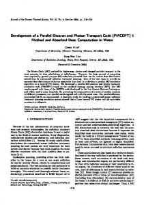
Based on the Figure 5 above, the selected beam is analysed via the Finite Element Method. As illustrated, three of the beam that is the horizontal beams are being fixed as the constraints since no any load applied. All the three horizontal beams as shown in figure have been applied to the calculated force of 489N. Other details are as follows:
Table 3: Particular details of the AISI 1005 Steel
(a)
Material Name Mass Density Modulus of Elasticity
AISI 1005 Steel 7.872e-009 N.s2 /mm/mm3 200000 N/mm2
Poisson’s ratio
0.29 (b)
(c)
Figure 6: The result obtained by using finite element analysis. (a) Displacement, (b) Stress von Mises, (c) Strain von Mises Based on the result obtained, the colour contour shows that the middle part of the middle beam has the highest displacement magnitude at 5.08565mm. It is obvious that the load (machine, shaft and top metal plate) exerted is uniform throughout the beam overly and therefore, the centre or the middle part of the middle beam will have the highest displacement since there is no any support from the bottom as how the four vertical beams at each corner are supporting the horizontal beam at all the ends. This material is sufficient enough to sustain the load exerted based on the value of the safety factor obtained. The other reasons for choosing this AISI 1005 Steel L – shaped hollow square bar as the main body frame for this engine test rig is that easy to handle these bars in term of cutting, welding, joining and other mechanical process. It is a very lightweight material which at the end of the day will ease for the mobility of the test rig frame from one place to another. To ensure this beam can support load force without failure, additional force exerted on the beam and being analysed again in finite element analysis. The result shown in Table 4 below.
11
Table 4: Comparison upon the additional force on the horizontal bar beam Force
Stress (N/mm2)
Strain (N/mm2)
Displacement
Min
Max
Min
Max
Min
Max
489N
0
214.7476
0
1.385 x 10⁻³
0
5.085648
978N
0
1097.27
0
7.077 x 10⁻³
0
12.161300
Based on the result obtained, it clearly shows that the beam still could support the load exerted although the force is doubled from the previous analysis. This is entirely done to prove that the beam could sustain the load, and for any amendment or modification cases whereby the grass cutter engines is needed to replace by a bigger size of the machine, which would double up the mass, and still can sustain by this engine test rig. As illustrated in Figure 6, the top part of the test rig, a horizontal metal plate with a thickness of 1mm of steel plate placed. This part is used to place the all the units of the engine’s throttle with cable wire that already assembled with a hollow solid cylinder like a gripper for it. This top part of test rig also used to place the laptop that programmed Arduino coding and the stepper motor with its circuit design for the throttle pulling testing. Then, rear part of the horizontal bar beam of test rig has drilled with 10 small holes evenly that used for the bracket purpose in order to tighten the grass cutter machine body frame with the middle part of horizontal part of the test rig. This is to avoid the machine from fall down from the test rig due to high vibration created when the engine gets started. Four units of 3 inch roller have been assembled for the test rig mobility purpose. Therefore, the whole design of test rigs for this project is simple, precise and easy to handle it for the demonstration purpose. Throttle
Test Rig
Fuel and Lubricant Tank Engine
Roller
Figure 7: Experimental set up with test rig with fabricated.
12
The second part of the result and discussion here is about the RPM and torque calculation for the solid cylinder shaft that welded at center of grass cutter. Petrol as fuel and 2T machine engine oil as lubricant are used for all the engines to run the machine for a few hours. By using tachometer, revolution per minute (RPM) reading was taken for 4 engines only and left one engine for the constant variable where it's being used for the engine parts comparison purpose with the other 4 engines that have been run. The readings of RPM value are shown in Table 5 below. Table 5: The RPM readings of engines Engine
At zero throttle turn
At half throttle turn
At full throttle turn
Engine 1
188.75
488.89
728.40
Engine 2
189.52
490.17
730.73
Engine 3
187.64
484.11
726.17
Engine 4
186.97
482.38
723.57
Based on the readings obtained, engine number 2 is having the highest value of the RPM reading among the other engines. This is because, from the observation when the engines are demonstrated to run it, shaft that welded at engine 2 shows very smooth rotational flow, which reduces the vibration produce by the engine itself as it attached in the test rig. Engine number 4 shows the lowest reading of RPM due to the welding defect of the solid cylinder rod shaft that’s not enough in perpendicular position of the metal plate during fabrication. Thus, engine number 4 produces more vibration when the engine is demonstrated to run and causes low in RPM reading even though the throttle turns applied is similar at the others. As for the wear effect, this group is assigned to observe and differentiate the wear on each cylinder block of the engines. To achieve that, each engine was run at different period of time and the cylinder blocks were analysed. The results are tabulated in Table 6 below.
13
Table 6: Wear on each cylinder block Engine
Engine 1 (Const)
Period of Running (min)
-
Engine 2
60
Engine 3
120
Engine 4
180
Engine 5
10
Cylinder Block Surface Condition
14
Wear can slightly be observe on the wall surface of cylinder block in engine 5 as it was ran for 10 minutes only. Wear can be observed on engine number 2, 3, and 4 as the time for the engine being operated is longer. Cylinder block in engine 4 shows a significant pattern of wear and can be observed clearly on the wall of the cylinder block. However, these wear patterns are somehow hardly visible as all the engines were brand new engines. The wear effect will occur if the engines were run for a longer period of time. Moreover, the mixture of 2T oil and petrol ratio should be 2:1 to reduce wear on the inside of the engine. RPM also played an important role in reducing the wear effect on the parts of the engines.
CONCLUSION
Finally, the project concluded that the test rig is suitable to serve for further analysis about the engine using different types of lubricant for testing purpose based on the finite element analysis. Furthermore, it is clearly observed and proved that all the parts interact with friction in the engine such piston, crankshaft ad cylinder block are affected by the engine oil used in terms of its weariness of engine components.
15
REFERENCES [1] [2] [3] [4] [5] [6] [7] [8] [9] [10] [11] [12]
[13] [14] [15] [16] [17] [18] [19]
J. B. Heywood, Internal combustion engine fundamentals vol. 930: Mcgraw-hill New York, 1988. M. N. Muhamad, "MILD Combustion: A Technical Review Towards Open Furnace Combustion," 2012. D. Ramasamy, K. Kadirgama, M. Rahman, and Z. Zainal, "ANALYSIS OF COMPRESSED NATURAL GAS BURN RATE AND FLAME PROPAGATION ON A SUB-COMPACT VEHICLE ENGINE," International Journal of Automotive & Mechanical Engineering, vol. 11, 2015. M. Sani, M. Noor, M. Zainury, M. Rejab, K. Kadirgama, and M. Rahman, "Investigation on modal transient response analysis of engine crankshaft structure," WIT Transactions on the Built Environment, vol. 112, pp. 419-428, 2010. M. Noor, A. P. Wandel, and T. Yusaf, "Design and development of mild combustion burner," Journal of Mechanical Engineering and Sciences, vol. 5, pp. 662-676, 2013. H. Siddalingappa R and H. Omprakash, "Performance and Combustion Characteristics of Single Cylinder Diesel Engine Running on Karanja Oil/Diesel Fuel Blends," Engineering, vol. 2011, 2011. M. N. Muhamad, "Finite Element Analysis on Thermal Effect of the Vehicle Engine," 2009. Y. A. Cengel, M. A. Boles, and M. Kanoğlu, Thermodynamics: an engineering approach vol. 5: McGraw-Hill New York, 2002. M. N. Muhamad, "Finite element based fatigue life prediction of a new free piston engine mounting," Journal of Applied Sciences, vol. 9, pp. 1612-1621, 2008. A. Wargante and S. Gawade, "Experimental Analysis Of Single Cylinder Diesel Engine," in International Journal of Engineering Research and Technology, 2013. W. W. Pulkrabek, Engineering fundamentals of the internal combustion engine: Prentice Hall, 2004. R. Ledbetter, H. Ulery Jr, and R. Ahlvin, "Traffic tests of airfield pavements for the jumbo jets," in Presented at the Third International Conference on the Structural Design of Asphalt Pavements, Grosvenor House, Park Lane, London, England, Sept. 11-15, 1972., 1972. B. Siuru, "Two-stroke Engines: Cleaner and Meaner," Mechanical Engineering, vol. 112, p. 66, 1990. V. Chase, "Propfans-A new twist for the propeller," Mechanical Engineering, vol. 108, pp. 46-50, 1986. B. Kareem, "Evaluation of failures in mechanical crankshafts of automobile based on expert opinion," Case Studies in Engineering Failure Analysis, vol. 3, pp. 25-33, 2015. N. Nikolic, T. Torovic, and Z. Antonic, "A procedure for constructing a theoretical wear diagram of IC engine crankshaft main bearings," Mechanism and Machine Theory, vol. 58, pp. 120-136, 2012. H. Meng and K. Ludema, "Wear models and predictive equations: their form and content," Wear, vol. 181, pp. 443-457, 1995. P. Flores, "Modeling and simulation of wear in revolute clearance joints in multibody systems," Mechanism and machine theory, vol. 44, pp. 1211-1222, 2009. S. Mukras, N. H. Kim, N. A. Mauntler, T. Schmitz, and W. G. Sawyer, "Comparison between elastic foundation and contact force models in wear analysis of planar multibody system," Journal of Tribology, vol. 132, p. 031604, 2010.
[20] Brójo, F., A. Santos, and J. Gregório. Computational Analysis of the Scavenging of a twostroke Opposed Piston Diesel Engine. in The 2010 International Conference of Mechanical Engineering, London, UK. 2010.
16
[21] Hinckel, P. and F.R. Naia, PRELIMINARY STUDY OF A POPPET VALVE TWO- STROKE ENGINE OPERATING WITH CONTROLLED AUTO IGNITION APPLIED TO POWER GENERATION. 2009. [22] Kumarappa, S. and G. Prabhukumar, Improving the performance of two stroke spark Ignition engine by direct electronic CNG injection. Editorial Board, 2008. 2(4): p. 169. [23] Mitianiec, W. and M. Forma, Analysis of direct fuel injection in a small power two-stroke engine. Journal of KONES, 2009. 16: p. 337-347. [24] Boretti, A. and J. Scalzo, A novel hydrogen engine one litre two stroke delivering top power 110 kW and brake efficiency 36% within the 25 kg total weight constraints. International Journal of Hydrogen Energy, 2013. 38(28): p. 12481-12488. [25] Ciccarelli, G., S. Reynolds, and P. Oliver, Development of a novel passive top–down uniflow scavenged two-stroke GDI engine. Experimental Thermal and Fluid Science, 2010. 34(2): p. 217-226. [26] Luján, J.M., et al., Heat transfer modeling in exhaust systems of high-performance twostroke engines. Applied Thermal Engineering, 2014. 69(1): p. 96-104. [27] Reddy, M.P., SOME INNOVATIONS IN DESIGN OF LOW COST VARIABLE COMPRESSION RATIO TWO STROKE PETROL ENGINE. [28] Pradeep, V., S. Bakshi, and A. Ramesh, Direct injection of gaseous LPG in a two-stroke SI engine for improved performance. Applied Thermal Engineering, 2015. 89: p. 738-747. [29] Dalla Nora, M. and H. Zhao, High load performance and combustion analysis of a fourvalve direct injection gasoline engine running in the two-stroke cycle. Applied Energy, 2015. 159: p. 117-131. [30]. Barjaneh, Afshin, and Hoseyn Sayyaadi. "A new closed-form thermodynamic model for thermal simulation of spark ignition internal combustion engines."Energy Conversion and Management 105 (2015): 607-616. [31]. Khalil, Ahmed EE, and Ashwani K. Gupta. "Internal entrainment effects on high intensity distributed combustion using non-intrusive diagnostics."Applied Energy 160 (2015): 467-476. [32]. : Wu, Zhijun, et al. "Thermal efficiency boundary analysis of an internal combustion Rankine cycle engine." Energy 94 (2016): 38-49. [33]. Hassan, Mohamed I., and Ayoola T. Brimmo. "Modeling In-Cylinder Water Injection in a 2-Stroke Internal Combustion Engine." Energy Procedia 75 (2015): 2331-2336. [34]. M. Karvonen, R. Kapoor, A. Uusitalo, and V. Ojanen, "Technology competition in the internal combustion engine waste heat recovery: a patent landscape analysis," Journal of Cleaner Production, 2015. [35]. Semlitsch, Bernhard, Yue Wang, and Mihai Mihăescu. "Flow effects due to valve and piston motion in an internal combustion engine exhaust port."Energy Conversion and Management 96 (2015): 18-30. [36]. Khalil, Ahmed EE, and Ashwani K. Gupta. "Impact of internal entrainment on high intensity distributed combustion." Applied Energy 156 (2015): 241-250. [37]. Kosenok, Boris B., and Valeriy B. Balyakin. "Study of the Dynamic Characteristics of a Two-cylinder Internal Combustion Engine Using Vector Models." Procedia Engineering 106 (2015): 183-191. [38]. Lu, Yong, Pucheng Pei, and Yongfeng Liu. "An evaluation of a 2/4-stroke switchable secondary expansion internal combustion engine." Applied Thermal Engineering 73.1 (2014): 325-334.
17
[39]. Strozzi, A., et al. "A repertoire of failures in connecting rods for internal combustion engines, and indications on traditional and advanced design methods." Engineering Failure Analysis (2015). [40]. Michalski, J. and P. Woś, The effect of cylinder liner surface topography on abrasive wear of piston–cylinder assembly in combustion engine. Wear, 2011. 271(3): p. 582-589. [41]. Gara, L., et al., Wear measurement of the cylinder liner of a single cylinder diesel engine using a replication method. Wear, 2010. 268(3): p. 558-564. [42]. Truhan, J.J., J. Qu, and P.J. Blau, A rig test to measure friction and wear of heavy duty diesel engine piston rings and cylinder liners using realistic lubricants. Tribology International, 2005. 38(3): p. 211-218. [43]. Yousfi, M., et al., Smoothness and plateauness contributions to the running-in friction and wear of stratified helical slide and plateau honed cylinder liners. Wear, 2014. [44]. Lenauer, C., et al., Piston ring wear and cylinder liner tribofilm in tribotests with lubricants artificially altered with ethanol combustion products. Tribology International, 2015. 82: p. 415-422. [45]. Obert, P., et al., The influence of oil supply and cylinder liner temperature on friction, wear and scuffing behavior of piston ring cylinder liner contacts–A new model test. Tribology International, 2016. 94: p. 306-314. [46]. Olander, P., P. Hollman, and S. Jacobson, Piston ring and cylinder liner wear aggravation caused by transition to greener ship transports–Comparison of samples from test rig and field. Wear, 2013. 302(1): p. 1345-1350. [47]. Profito, F.J., E. Tomanik, and D.C. Zachariadis, Effect of cylinder liner wear on the mixed lubrication regime of TLOCRs. Tribology International, 201.