W wyniku badaÅ ustalono, że zastosowana obróbka cieplna bimetalu zasadniczo zmienia stan naprÄżeÅ wÅasnych w warstwie tytanu. Próbki bez.
A
R
C
H
I
V
E
S
O
F
M
E
T A
L
L
Volume 59
U
R
G
Y
A
N
D
M
A T
2014
E
R
I
A
L
S
Issue 3
DOI: 10.2478/amm-2014-0195
A. KAROLCZUK∗ , M. KOWALSKI∗ , K. KLUGER∗ , F. ŻOK∗∗
IDENTIFICATION OF RESIDUAL STRESS PHENOMENA BASED ON THE HOLE DRILLING METHOD IN EXPLOSIVELY WELDED STEEL-TITANIUM COMPOSITE
IDENTYFIKACJA NAPRĘŻEŃ WŁASNYCH METODĄ NAWIERCANIA OTWORU W BIMETALU STAL-TYTAN OTRZYMANEGO TECHNOLOGIĄ ZGRZEWANIA WYBUCHOWEGO
The hole drilling method was used to determine residual stresses in bimetallic composite manufactured by explosive welding process. The analyzed bimetal consist of titanium Grade 1 (6 mm) and S355J2+N steel (40 mm). The aim of the paper is to establish the influence of the heat treatment on residual stress state in titanium layer. Residual stress calculations were performed according to standards developed by strain gauge manufacturer (TML) and ASTM standards. The main conclusion is the heat treatment considerably changes the residual stress state in titanium layer from tensile stress state (no heat treatment) to compression stress state (after the heat treatment). Keywords: explosive welding, residual stresses, bimetallic composite, titanium grade 1
W pracy przedstawiono wyniki badań naprężeń resztkowych, wyznaczonych metodą nawiercania, w bimetalu stal-tytan otrzymanego w procesie zgrzewania wybuchowego. Analizowany bimetal to kompozyt stali S355J2+N (40 mm) oraz tytanu Grade 1 (6 mm). Celem badania było ustalenie wpływu obróbki cieplnej na kierunki i wartości naprężeń własnych w warstwie tytanu. Obliczenia naprężeń resztkowych przeprowadzono przy zastosowaniu: (i) procedury zalecanej przez producenta (TML) zastosowanych rozet tensometrycznych oraz (ii) zaleceń ASTM (American Society for Testing and Materials). W wyniku badań ustalono, że zastosowana obróbka cieplna bimetalu zasadniczo zmienia stan naprężeń własnych w warstwie tytanu. Próbki bez obróbki cieplnej wykazują naprężenia resztkowe rozciągające a w próbkach po obróbce cieplnej panują naprężenia ściskające.
1. Introduction Composite materials produced from metallic materials and their alloys have wide range of application in different industrial branches. Durable connection between two materials with different properties enables obtaining of new groups of materials meeting new higher requirements. Joint of the titanium resistant to aggressive environment and high strength steel finds application in chemical processing equipment. Another example of bimetallic material applications are structural transition joints used in shipbuilding industry, high loaded slide bearings, metallurgical aggregates, turbine blades, chemical reactors [1-4]. Explosive welding technology allows production of metallic composites through the use of detonation energy. High pressure generated during explosives detonation cause collision of joined materials and creates joint between them. Explosive welding is classified as a solid state metal joining process [3]. Because explosive welding causes considerable deformations, explosively welded plates are usually subjected to cold flattening process. Depending on the joined material properties heat treatment is used to avoid material cracking during cold rolling. One of the main problem concerning explosively welded materials is residual stress deter∗ ∗∗
OPOLE UNIVERSITY OF TECHNOLOGY, 5 MIKOLAJCZYKA STR., 45-271 OPOLE, POLAND Z.T.W „EXPLOMET” S.J., 100H OŚWIECIMSKA STR., 45-641 OPOLE, POLAND
mination. Information about the initial stress state (residual stress) is important for proper estimation of material behavior under monotonic and fatigue loading [5-7]. It is also helpful in selecting the explosive parameters. Residual stresses are created during technological processes as effect of thermal, mechanical or chemical affects causing plastic and elastic strains in the material. High value of residual stress in construction material can strongly influence overall operational safety and properties of mechanical systems. In general meaning, residual stress is function of the many factors like material structure or type of technological treatment [8]. The paper presents results of the residual stress measurements performed on steel titanium bimetallic plates without and after the heat treatment. 2. Experimental research Residual stress measurements were performed using the hole drilling method that consists of strain measurements around the drilled hole. Drilling results in a change of the strain state (stress relaxation). Registered change of the stain value is calculated to the residual stresses. The hole drilling method is known as partially destructive method [9]. Re-
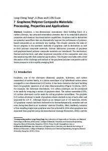
1120 searches were performed on six S355J2+N steel–Titanium Grade 1 specimens (210×180×46 mm) cut out from large (4330×3150×46 mm) bimetallic plates produced in explosive welding technology (Fig. 1). The specimens were taken out from area assigned for certification tests. The specimens were separated into two groups: first group was cut out form large plates just after welding process; second one was collected after the heat treatment and cold rolling. Mechanical properties and chemical composition of joined materials are presented in Tables 1 and 2. TABLE 1 Chemical composition steel S355J2+N (EN 10025-2:2004) and titanium Grade 1 Steel S355J2 Chemical element:
C
Si
Mn
P
S
The heat treatment performed on the bimetallic plates consisted of soaking in 600◦ C for 90 minutes and cooling with furnace to 150◦ C with 100◦ C/h cooling rate. Residual stress measurements were performed in two points for each plate in the titanium layer. Experimental setup used in presented research consisted of TML strain gauges (Table 3) connected to National Instruments SCXI-1520 acquisition setup. The holes were drilled using 1.5 mm diameter drill with Proxxon BFW 40/E driller (6000rpm rotational velocity). Strain gauge technical details are presented in Table 3. Distinct strain extremes visible in Fig. 2 indicate the drilling process, but only the stabilized strain values (the flat lines in Fig. 2) were taken into account and used as measured values. Residual stress calculations were performed according to standards developed by strain gauge manufacturer (TML) and ASTM standards separately [9].
Cu
Maximum content, % weight: 0,22 0,55 1,60 0,025 0,025 0,45
TABLE 3 Strain gauge technical data
Titanium Grade 1 Chemical element:
C
Fe
H
N
Maximum content, % weight: 0,10 0,20 0,015 0,03
O
Ti
0,18 99,5
TABLE 2 Mechanical properties of the steel S355J2+N and titanium Grade 1 Material
Mechanical properties ReH , MPa Rm , MPa E, GPa G, GPa ∗
∗
S355J2 382-395 598-605 189-215 Grade 1 308-324∗ (R p02 )∗ ∗ – manufacturer certificate, explosive welding
∗∗
206
84
100
38
ν, −
A5 , %
Manofacturer: TML TokyoSokkiKenkyujo Co., Ltd. Type:FRS-2 Dimensions : gauge length: 1.5 mm width: 1.3 mm outer diameter: ϕ9.5 mm Centerline diameter: ϕ5.14 mm Nominal resistance: 120 ± 0.5 Ω Gauge factor: 2.0
0,27-0,30 24-34∗ 0,37∗∗
43-56∗
– own research (titanium after
Fig. 2. Example strain history (for single strain gauge) registered in titanium during the drilling process, (a) – the specimen cut out just after explosive welding process, (b) – the specimen after the heat treatment and cold rolling
In order to investigate influence of the detonation wave direction on the maximum principal residual stress direction in bimetal layers angles between A strain gauge and detonation directions were determined for each measurement point (Fig. 3).
Fig. 1. Example photos of: (a) – the bimetallic plate with visible specimen cut out area (b) the specimen (210×180×46 mm) with the glued strain gauges (plate II without the heat treatment, arrow indicates the detonation direction)
Fig. 3. The specimen with strain gauges (plate I before heat treatment, titanium side), detonation and gauges directions are marked in form of arrows
1121 Example measurement results are presented in form of dependence between the hole depth h and registered stabilized strains in each strain gauge direction: A, B, C (Fig. 4). Characteristic feature of the obtained results is change of the strain sign. The specimens without the heat treatment are characterized by negative strain values indicating tensile residual stresses in the material. In specimens after the heat treatment positive value of measured strain indicated compressing residual stresses.
TABLE 4 The principal residual stresses σ1 , σ2 computed according to the TML procedure and angles defining the maximum principal stress direction θ(σ1 ) and detonation wave direction θ(P) for the specimens without the heat treatment Point 1
Plate
σ1
σ2
Point 2
θ(σ1 )
θ(P)
σ1
σ2
θ(σ1 )
θ(P)
I
235 227
-50
-12
269 213
-34
-20
II
243 210
-35
174
373 339
-125
99
IV
313 248
-2
-100 310 220
-43
-130
Where: θ(σ1 ) – angle measured clockwise from direction A to σ1 ; θ(P) – angle measured clockwise to A direction from detonation direction.
Fig. 4. Measured strain values in titanium layer, registered for A,B,C directions in dependence of hole depth, (a) – plate I without heat treatment and cold rolling, (b) plate I after heat treatment
TABLE 5 The principal residual stresses σ1 , σ2 computed according to the TML procedure and angles defining the maximum principal stress direction θ(σ1 ) and detonation wave direction θ(P) for the specimens after the heat treatment and flattening Point 1
Plate
3. Residual stress calculations according to strain gauge manufacturer’s prescriptions Strain gauge manufacturer TML recommends calculation method based on strain measurement performed for single hole depth equal to 1.2d, where d is the hole diameter. For 1.5 mm drill used in described research calculations were performed using strain (in A,B,C directions) registered for h =1.8 mm hole depth. Assuming uniform residual stress distribution the following computation steps has been done: θ=
1 εa + εc − 2εb nπ a tan − 2 εc − εa 2
(1)
where θ is angle defining principal stress orientation measured clockwise from A direction to σ1 ; εa , εb , εc are strain measured in A,B,C directions; n =0 for εa >εc ; n =1 for εa


![Tension Testing of Metallic Materials [Metric]1](https://m.moam.info/img/260x300/tension-testing-of-metallic-materials-metric1_5c178078097c4786128b4688.jpg)