W modelowaniu numerycznym, wybór odpowiedniego modelu turbulencji jest kluczowy, ponieważ ma ogromny wpływ na strukturę przepływu płynu w ...
A
R
C
H
I
V
E
S
O
F
M
E
T A
L
L
Volume 60
U
R
G
Y
A
N
D
M
A T
E
R
I
A
2015
L
S
Issue 1
DOI: 10.1515/amm-2015-0034
M. WARZECHA∗ , T. MERDER∗∗ , P. WARZECHA∗
INVESTIGATION OF THE FLOW STRUCTURE IN THE TUNDISH WITH THE USE OF RANS AND LES METHODS
METODY RANS I LES A STRUKTURA PRZEPŁYWU W KADZI POŚREDNIEJ
The liquid steel flow structure in the tundish has a very substantial effect on the quality of the final product and on efficient casting conditions. Numerous model studies are being carried out to explain the effect of the tundish working conditions on casting processes. It is necessary to analyze the structure of liquid steel flow, which is strongly supported with numerical modeling. In numerical modeling, a choice of a proper turbulence model is crucial as it has a great impact on the flow structure of the fluid in the analyzed test facility. So far most numerical simulations has been done using RANS method (Reynolds-averaged Navier-Stokes equations) but in that case one get information about the averaged values of the turbulent flow. In presented study, numerical simulations using large eddy simulations (LES) method were used and compared to RANS results. In both cases, numerical simulations are carried out with the finite-volume commercial code AnsysFluent. Keywords: tundish, continuous casting, numerical modeling
Struktura przepływu ciekłej stali w kadzi pośredniej ma bardzo istotny wpływ na warunki odlewania, a tym samym na jakość wyrobu końcowego. W celu określenia struktury przepływu w kadzi oraz analizy jej wpływu na warunki pracy urządzenia do ciągłego odlewania stali (COS) prowadzone są liczne badania modelowe: fizykalne i numeryczne. W modelowaniu numerycznym, wybór odpowiedniego modelu turbulencji jest kluczowy, ponieważ ma ogromny wpływ na strukturę przepływu płynu w analizowanym obiekcie badawczym. Do tej pory, największą ilość symulacji numerycznych przeprowadzono z wykorzystaniem metody RANS (Reynolds-averaged Navier-Stokes equations). W przypadku tej metody dostajemy jednak jedynie informacje o uśrednionych wartościach przepływu turbulentnego, z jakim mamy do czynienia w kadziach pośrednich. W prezentowanej pracy natomiast, przedstawiono wyniki symulacji numerycznych przeprowadzonych z wykorzystaniem metody wielkich wirów (Large Eddy Simulation, LES) i porównano je z wynikami RANS. W obu przypadkach, symulacje numeryczne zostały przeprowadzone z wykorzystaniem komercyjnego kodu AnsysFluent.
1. Introduction Mathematical models are nowadays the basis for numerical modeling of industrial processes as for example continuous casting of steel. This is due to the fact that investigation of the steel flow field in the continuous casting tundish or removing of non-metallic inclusions in an industrial environment is – due to the high temperatures of the process and the opacity of the liquid steel – difficult, and in some cases even impossible to perform. An adequate and well-developed mathematical model, with appropriate initial and boundary conditions, should be able to reproduce the phenomenon occurring during the steel flow in the real plant [1]. To do so, the results of simulations have to be validated with experimental results, performed on the real plants or at least on its laboratory models. This gives the various opportunities for research to explain the phenomena accompanying the flow of liquid steel in various tundishes during casting process. Most of CFD (Computational Fluid Dynamics) studies in the field ∗ ∗∗
of continuous casting were performed with commercial codes, such as Ansys Fluent [2,3] or Phoenics [4,5]. Carried out researches are related to many aspects of the analysis technique of steel casting, including the steel flow and changes of the flow conditions with flow control devices (FCD) [6-8], the residence time distribution [9-11], heat transfer [12,13], and transport and separation of non-metallic inclusions into steel [14-16]. The flow field inside the tundish is strongly investigated with numerical modeling and numerous studies can be found in literature. The turbulence of liquid steel in the tundish is difficult to map accurately [17]. There are areas with a high level of turbulence (shroud and nozzles), and areas with the laminar movement. Since most of numerical researches performed so far are done with RANS method (Reynolds-averaged Navier–Stokes equations), for turbulence modeling, the standard [6,18] or realizable [19,20] k-ε models are mostly used, rather RSM [21,22] (Reynolds Stress Model). In numerical modeling, a choice of a proper turbulence model
CZESTOCHOWA UNIVERSITY OF TECHNOLOGY, DEPARTMENT OF METALS EXTRACTION AND RECIRCULATION, 19 ARMII KRAJOWEJ AV., 42-201 CZĘSTOCHOWA, POLAND SILESIAN UNIVERSITY OF TECHNOLOGY, INSTITUTE OF METALS TECHNOLOGY, 8 KRASINSKIEGO STR., 40-019 KATOWICE, POLAND
216 is crucial as it has a great impact on the flow structure of the fluid in the analyzed test facility. In the analysis of the turbulent flow using RANS method one get the averaged values. In case of LES method (Large Eddy Simulation), all the large turbulent scales are solved directly and only the small scales that are smaller than the filter size are modeled. From those simulations one get also the information about the instantaneous velocity field inside the tundish.
2. Investigated tundish
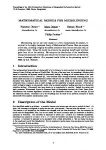
The investigated object is a six-strand continuous casting tundish of a channel-shaped type, equipped with two overflow partitions. The tundish is symmetrical relative to the transverse plane. The nominal capacity of the tundish is 34-tons of liquid steel. It feeds simultaneously six molds for the production of billets with a cross section of 280×300 mm. In its base configuration the tundish is equipped with a pair of dams. During steady-state casting, with all Submerged Entry Nozzles (SENs) working, the investigated tundish is characterized by a molten steel mass flow of a 138 t/h. The tundish is used for sequence casting with about ten heats. The shape of the tundish together with its basic dimensions are shown in Fig. 1. Table 1 shows the technological operating conditions of the tundish, used also in numerical simulations.
TABLE 1 Dimensions of the 34 t continuous casting tundish Parameters
Value
Units
Nominal capacity
34
ton
Molten steel level
570
mm
Shroud diameter
86
mm
SENs diameter
36
mm
Number of tundish nozzles
6
-
0.7
m/min
280×300
mm
Dam height
300
mm
Dam width
100
mm
Casting speed Billets
The geometry of presented tundish is symmetrical in two planes of symmetry. In the case of calculation performed using RANS method it would be sufficient to calculate only a quarter of the computational domain assuming symmetry boundary conditions at the intersection inside the tundish. Such an assumption could not be used for unsteady simulation using LES method, as this would influence the results – particularly instantaneous solution (this will be shown further in this paper). Due to that authors decided to use full tundish geometry for both methods. Presented studies are continuation of the previous research performed with tundish water model and RANS calculations [22].
Fig. 1. Shape (a) and characteristic dimensions (b) of the investigated tundish
3. Numerical modeling procedures In LES method (Large Eddy Simulation) a spatial filtering is used to filter out all the scales smaller than the filter size. Using the density-weighted averaging, filtered variables can be written in the form: Z ϕ˜ = ϕ(x 0 )G(x − x 0 )dx 0 (1) D
where D is the computational domain and G is a filter function that determines the size of the resolved scales. The structures that are smaller than the filter size are considered to be unknown and must be modeled. As a result of spatial filtering and Favre averaging procedure applied to continuity and momentum equations, one obtain a system of differential Navier-Stokes equations for LES method: ∂u˜i =0 ∂xi ∂ 1 ∂p ∂ µe f f ∂u˜i ∂u˜ j ∂u˜i + (u˜i u˜ j ) = − + + ∂t ∂x j ρ ∂xi ∂x j ρ ∂x j ∂xi with viscosity defined as: µe f f = µ + µt
(2) ! (3)
(4)
Using Smagorinsky model [23], subgrid scale turbulent viscosity is described as: (5) µt = (Cs ∆)2 S˜ where
∆ = (∆x∆y∆z)1/3 q S˜ = 2S S ij ij
(6) (7)
Cs is a Smagorinsky model constant (Cs =0.1), and the strain rate tensor is defined as: ! 1 ∂u˜i ∂u˜ j Si j = + (8) 2 ∂x j ∂xi
217 To solve the differential equation system, it is necessary to assume suitable initial and boundary conditions, corresponding to the industrial process conditions. To correspond with the real casting conditions in investigated process, the boundary condition for steel flowing through the shroud equals for the velocity of 2.2 m/s and turbulent intensity of 5%. The boundary conditions used in computations are shown in Fig. 2.
Computational grid set at walls of the tundish working space is shown in Fig. 3. The mesh is finer in the shroud and the tundish nozzles regions. TABLE 3 Parameters and solver settings for analyzed test cases Parameters
Case A
Case B
RANS
LES
k-epsilon Standard Wall Function
Smagorinsky-Lilly Standard Wall Function
Geometry
3D
3D
Mesh typ
hexa
hexa
Number of cells Node average distance (whole tundish) Node average distance (inlet region)
0.9 mln
2.0 mln
24 mm
15 mm
6.7 mm
6 mm
Time dependency
steady
unsteady
Turbulence method Model Near-wall treatment
Fig. 2. Boundary conditions set for numerical simulations
In numerical simulation a Standard Wall function has been used (on the bottom and side walls) which based on the work of Launder and Spalding [24]. For both RANS and LES methods the relation between temperature and heat transfer at the wall is defined as: Cµ1/4 kw1/2 2 1 ∗ Pr y + ρ Pr u (y∗ < yT∗ ) 1/2 2 h qw i (T w − T )ρc p kw 1 ∗ = Prt κ ln(Ey ) + P + qw o 1/4 1/2 n C k µ w 1 ρ Prt u2w + (Pr − Prt )u2c (y∗ > y∗ ) 2
T
qw
(9) Where yT∗ is a non-dimentional thermal boundary thickness, defined as a value at which the linear law and the logarithmic law intersect and uc is the mean velocity at the distance y∗ = yT∗ from the wall. P is defined as: ! i Pr 3/4 h P = 9.24 − 1 1 + 0.28e−0.007 Pr / Prt Pr t
TABLE 2 Operating conditions used for numerical simulations Value
Units
Liquid steel density
7010
kg/m3
Liquid steel dynamic viscosity
0.007
kg/m s
2.0
m/s
Inlet temperature
1823
K
Specific heat
821
J/kg K
Thermal conductivity
30.5
W/m K
Heat flux through side and bottom walls
-2.6
kW/m2
Heat flux through slag cover
-16
kW/m2
Inlet velocity
-
0.01
Pressure velocity coupling
SIMPLE
SIMPLE
Pressure discretisation
Standard Second Order Upwind
Standard Bounded Central Differencing
AnsysFluent 14 [24]
AnsysFluent 14
Momentum discretisation CFD code
(10)
In case of LES method Cµ values in equation (9) is replaced with the model constant Cs . Detailed boundary and operating conditions which correspond to the conditions of the industrial process can be found in Table 2. In numerical simulations two cases were studied (Table 3).
Parameters
Time step size [s]
Fig. 3. Computational mesh set at walls of the tundish
4. Results and discussion The aim of the performed studies was to analyze the flow structure and liquid steel temperature distribution. The results of calculations performed with LES numerical method were compared to RANS results. Numerical model allow to diagnose the working conditions of the investigated tundish. Three-dimensional distributions of steel velocity, as well as the fields of temperature concentrations in the tundish working space, provide a source of good knowledge about steel casting conditions. In this section, detailed contour maps of the velocity vectors and temperature fields of liquid steel inside the tundish obtained using LES method are presented and compared to RANS results.
218 Velocity fields and velocity vectors distributions for considered tundish configuration are presented in Fig. 4 and 5. For better analysis of velocity field a maximum and cut-off values were used (left and right columns respectively). The results are presented for the cross section passing through the tundish nozzles. Final results obtained using steady state RANS method were used as an initial condition for LES method. In the case of LES method, mean and instantaneous fields are shown. Mean results correspond to the average values obtained over 3000 seconds of the flow field and the instantaneous value is shown at the final state of the flow field which is t=3000 seconds. Comparing mean velocity field for RANS and LES methods (see Fig. 4a and 4b respectively) one can observe similar velocity distribution close to the inlet area. The differences start to appear in the regions close to the outer SEN’s (number 1, 2, 5 and 6). In this region velocity field obtained using LES method is higher compared to RANS results. LES method provides also information about the instantaneous velocity field, which is presented in Fig. 4c. The differences in the velocity filed obtained with RANS and LES methods is also visible in the velocity vectors filed presented in Fig. 5. Higher movements of the liquid steel between SEN’s 1 and 2 and also 5 and 6 is detected by the LES method, whereas for RANS method the velocity in this region is close to 0m/s. This is also confirmed on the velocity field plotted on the measurement lines presented in Fig. 7. This leads to weaker liquid steel mixing in those regions. This is also confirmed by the temperature distribution inside the tundish working space presented in Fig. 8.
Fig. 4. Liquid steel velocity field: RANS (a), LES – mean values (b), LES – instantaneous values (c)
Fig. 5. Liquid steel velocity vectors: RANS (a), LES – mean values (b), LES – instantaneous values (c)
Fig. 6. Location of measurement lines: Measurement line 1 at height Z=0.4m, Measurement line 2 at height Z=0.25m, Measurement line 3 at height Z=0.1m
Fig. 7. Velocity distribution in the outlet plane of symmetry: Measurement line 1 (a), Measurement line 2 (b), Measurement line 3 (c)
219 Results obtained with RANS method show higher differences in liquid steel temperatures between inlet zone of the tundish and outer area (close to SEN’s 1 and 6). Due to the better liquid steel mixing predicted by LES method, the temperature field is more uniform in the whole tundish.
tundish areas is possible and liquid steel temperature casted at individual strands is more homogenous. This, in turn, provides stability of the continuous casting process.
5. Summary and conclusions
Fig. 8. Liquid steel temperature distribution: RANS (a), LES – mean values (b), LES – instantaneous values (c)
Comparing the temperature drop along the investigated tundish for both RANS and LES methods one may observe that this difference is not big – 6 to 12 K – compared to the temperature of incoming liquid steel – 1823 K. In the case of RANS method the temperature drop is bigger and the lowest temperature values are seen in the regions close to the side walls. This can be influenced by the small value of turbulence intensity in those regions and therefore worse mixing. As the LES method is more accurate one may see the temperature distribution drop to be more homogenous along the tunidsh (see Fig. 9). Nevertheless, thanks to the flow structure changes caused by the dams, one can observe very low differences between the temperature of incoming steel and the temperature of steel at the ends of the tundish for both RANS and LES methods. With dams, which main task is to control the flow of the liquid steel stream, the movement of warmer fluid in the further
Investigated tundish is characterized by the thin shape and relatively high ratio of the tundish length to the width, as for common multi-strand tundishes in local steel industry. High velocity of the incoming fluid decreases outside inlet area which is determine by dams. By installation of a pair of dams, two working spaces have been created. The inlet zone is separated from the nozzle zone, which as a consequence should reduce of the transient zone and increase the share of dispersed plug flow. The results of simulations performed with two other turbulence methods – RANS and LES - have shown the differences for both investigated phenomena: flow field and temperature distribution. It has been shown that LES method indicate more particularly the fluid movement in regions of the tundish which are characterized with higher difference of the calculated variables. Presented numerical simulations demonstrate the differences in the calculations of the tundish carried out using RANS and LES methods. In order to determine weather the models show similar results it was enough to make the calculations for one configuration of the tundish. The current model show slight difference in modeling using both methods. However, it is necessary to verify the obtained results based on the experimental data of industrial measurements (temperature measurements and RTD curves). Properly validated model can be used in the further study to analyze the impact of building the working space (flow modifiers) to remove the inclusions from steel and thus increase its purity. Currently, studies on the impact of the LES method on the results concerning the characteristics of the RTD (along with verification of industrial data) in the tundish and non-metallic inclusions separation from liquid steel are performed.
Fig. 9. Temperature distribution in the outlet plane of symmetry: Measurement line 1 (a), Measurement line 2 (b), Measurement line 3 (c)
220 REFERENCES Nomenclature A
Van Driest constant (=26)
cp
specific heat
De f f effective diffusion coefficient Dm
molecular diffusion coefficient
Dt
turbulent diffusion coefficient
gi
gravitational acceleration
k
turbulence kinetic energy
ke f f effective thermal conductivity kp
turbulent kinetic energy at the first near-wall node
mt
mass of the tracer
p
pressure
P
Prandtl number
Pt
turbulent Prandtl number
q
wall heat flux
Si j
strain rate tensor
t
time
t¯
theoretical (mean) residence time
tav
mean residence time
T
temperature
u
velocity
ui, j , velocity components V
volume of liquid in the tundish
µ
dynamic viscosity
µe f f effective viscosity µt
turbulent viscosity
ν
kinematic viscosity
ρ
specific density
ρst
liquid steel density
ρinc
inclusion density Acknowledgements
To the National Centre for Research and Development for financial support (project No PBS2/A5/32/2013). This research was also supported in part by PL-Grid Infrastructure.
Received: 20 March 2014.
[1] M. Warzecha, T. Merder, Metalurgija 52, 153-156 (2013). [2] V. Singh, A.R. Pal, P. Panigrahi, ISIJ Int. 48, 430-442 (2008). [3] R.K. Singh, A. Paul, A.K. Ray, Scand. J. Metall. 32, 137-147 (2003). [4] L. Zhang, S. Taniguchi, K. Cai, Metal. and Mater. Trans. B 31, 253-268 (2000). [5] H. Solhed, J. Alexis, U. Sjostrom, S.D. Yuan, L. Jonsson, Scand. J. Metall. 29, 127-238 (2000). [6] L. Zhong, B. Li, Y. Zhu, R. Wang, W. Wang, X. Zhang, ISIJ Int. 47, 88-98 (2007). [7] T. Merder, Materials Science Forum 654-656, 1557-1560 (2010). [8] M. Warzecha, T. Merder, P. Warzecha, Metalurgija 53, 439-442 (2014). [9] A. Robert, D. Mazumdar, Steel Res. Int. 72, 3, 97-105 (2001). [10] A. Kumar, S.C. Koria, D. Mazumdar, ISIJ Int. 44, 12, 1217-1224 (2004). [11] T. Zhou, M. Li, Q. Li, B. Lei, Q. Chenn, J. Zhou, Trans. Nonferrous Met. Soc. China 24, 1117-1124 (2014). [12] D.Y. Sheng, L. Jonsson, Metal. and Mater. Trans. B 30, 979-987 (1999). [13] L. Zhang, Steel Res. Int. 76, 11, 784-799 (2005). [14] M. Javurek, P. Gittler, R. Roessler, B. Kaufmann, H. Presslinger, Steel Res. Int. 76, 1, 64-70 (2005). [15] D.S. Kumar, T. Rajendra, A. Sarkar, R. Prasad, M. Ranjan, Iron&Steelmaking 36, 470-482 (2009). [16] G. Luo-fang, L. Hong, L. Hai-tao, W. Yao, S. Wen-chen, Steel Res. Int. 20, 7-12 (2013). [17] O.J. Illegbussi, ISIJ Int. 34, 732-746 (1994). [18] K. Raghavendra, S. Sarkar, S.K. Ajmani, M.B. Denys, M.K. Singh, Applied Math. Modelling 37, 6284-6300 (2013). [19] A. Kumar, S. Chakraborty, N. Chakraborti, Steel Res. Int. 78, 517-521 (2007). [20] L. ChaoxIang, L. B Iao, Z. Shengyu, AASRI Procedia 3, 313-318 (2012). [21] A. Najera-Bastida, L. Garcia-Demedices, P. Ramirez-Lopez, E. Torres-Alonso, R.D. Morales, Steel Res. Int. 78, 318-326 (2007). [22] M. Warzecha, T. Merder, H. Pfeifer, J. Pieprzyca, Steel Res. Int. 81, 11, 987-993 (2010). [23] J. Smagorinsky, Month. Wea. Rev. 91, 99-108 (1963). [24] ANSYSFluent, User’s guide, version 14.0, Fluent Inc.