fNokia Research Center Bochum, Meesmannstrasse 103, 44807 Bochum, Germany .... The call of a test case by the control component can be seen as the ...
1
An Introduction into the Testing and Test Control Notation (TTCN-3)
Jens Grabowskia , Dieter Hogrefeb , Gyorgy R�ethyc , Ina Schieferdeckerd , Anthony Wilese and Colin Willcockf a Institute
for Telematics, University of Lubeck, Ratzeburger Allee 160, 23538 Lubeck,
b Institute
for Informatics, University of Gottingen, Lotzestrasse 16-18, 37083 Gottingen,
c Ericsson
Hungary, Laborc street 1, 1037 Budapest, Hungary
Germany Germany
d Fraunhofer
FOKUS, Kaiserin-Augusta-Allee 31, 10589 Berlin, Germany
e European
Telecommunications Standards Institute (ETSI), 650, route des Lucioles, 06921 Sophia-Antipolis Cedex, France f Nokia
Research Center Bochum, Meesmannstrasse 103, 44807 Bochum, Germany
The Testing and Test Control Notation (TTCN-3) is a new test speci cation and test implementation language that supports all kinds of black-box testing of distributed systems. TTCN-3 was developed in the years 1999 to 2002 at the European Telecommunications Standards Institute (ETSI), as a redesign of the Tree and Tabular Combined Notation (TTCN) standard (ITU-T Rec. X.292). TTCN-3 is built from a textual core language that provides interfaces to di�erent data description languages and the possibility of di�erent presentation formats. This makes TTCN-3 quite universal and application independent. TTCN-3 is being published as the ITU-T Rec. Z.140 series. This paper provides an introduction to TTCN-3. This includes an overall view of the TTCN-3 core language, a description of the existing presentation formats, an explanation of the implementation of TTCN-3-based test systems and a discussion about the current usage and the future of the language. The authors all participated in the work within ETSI.
1. INTRODUCTION The Testing and Test Control Notation (TTCN-3) [5,7,12] was designed in such a way that a broad user community is addressed. TTCN-3 has removed many of the peculiarities of the speci c application domain of OSI and conformance testing that were present in previous versions of the Tree and Tabular Combined Notation TTCN [9]1 . The syntax looks similar to a typical programming language like C, C++ or Java and should therefore be easy to understand and apply for someone familiar with programming. 1 ITU-T
Rec. X.292 is identical to part 3 of ISO/IEC IS 9646 [8]. The latest corrections of TTCN have been published as ETSI Technical Report 101 666 [6]
2 Textual Format
ASN.1 (Abstract Syntax Notation One)
IDL (Interface Definition Language)
Other Data Descriptions
TTCN-3 Core Notation
Tabular Presentation Format (TFT)
Graphical Presentation Format (GFT)
TTCN-3 User
Other Presentation Formats
Figure 1. Overall picture of TTCN-3
TTCN-3 is a exible and powerful language, applicable to the speci cation of all types of reactive system tests over a variety of communication interfaces. Typical areas of application are protocol testing (including mobile and Internet protocols), service testing (including supplementary services), module testing, testing of CORBA based platforms and the testing of APIs. As shown in gure 1, TTCN-3 is built from a textual core language that provides interfaces to di�erent data description languages and the possibility of di�erent presentation formats. From a syntactical point of view TTCN-3 is very different from TTCN. However, much of the well-proven basic functionality of TTCN has been retained, and in some cases enhanced. This paper is organized in the following manner. In the rst section, the key concepts associated with TTCN-3 are introduced together with their respective semantics. Building on these concepts the next section describes the TTCN-3 core language by using the example of a simpli ed automated teller machine (ATM). The next section of the paper considers the TTCN-3 presentation formats including the tabular presentation format TFT and the graphical presentation format GFT. In section 5 the use of TTCN-3 with other languages is described and in section 6, the execution interfaces of TTCN-3 are introduced, namely the TTCN-3 runtime interface (TRI) and the TTCN-3 control interface (TCI). Section 7 provides some examples of the application of TTCN-3 in industrial environments and standardization. The last section provides a summary and outlook.
2. CONCEPTS OF TTCN-3 TTCN-3 is based on concepts, which are independent of any syntax. These concepts are related to modules, test cases, test systems, test verdicts, components and defaults. This section presents these concepts. In some cases, the explanations use terms, which are keywords in the TTCN-3 core language. These terms are printed bold-faced.
3 create, start and stop
Test System stop
create,start and stop
stop
stop
PTCs PTC
MTC
stop stop ports Test System Interface
System Under Test (SUT)
Figure 2. Dynamic and concurrent test system
2.1. Modules and test cases
The principle building-blocks of TTCN-3 are modules. A module is a self-contained and complete speci cation, i.e., it can be parsed and compiled as a separate entity. A module consists of a module de nitions part and a module control part. The module de nitions part speci es the top-level de nitions of the module. These de nitions may be used elsewhere in the module, including the module control part. The module control part is the main program of a TTCN-3 module. It describes the execution sequence (possibly repetitious) of the actual test cases. Test cases are de ned in the module de nitions part and then called in the control part. The test cases de ne the behaviours, which have to be executed to check whether the system under test (SUT) passes the test or not. Like a module, a test case is considered to be a self-contained and complete speci cation that checks a test purpose. The result of a test case execution is a test verdict (section 2.3).
2.2. Test system
A test case is executed by a test system. TTCN-3 allows the speci cation of dynamic and concurrent test systems. A test system consists of a set of interconnected test components with well-de ned communication ports and an explicit test system interface, which de nes the boundaries of the test system ( gure 2). Within every test system, there is one Main Test Component (MTC). All other test components are called Parallel Test Components (PTCs). The MTC is created and started automatically at the beginning of each test case execution. A test case terminates when the MTC terminates. The behaviour of the MTC is speci ed in the body of the test case de nition. During the execution of a test case, PTCs can be created, started and stopped dynamically. A test component may stop itself or can be stopped by another test component. For communication purposes, each test component owns a set of local ports. Each port
4 Connected Ports
Test system IN
OUT
OUT
IN
Test Component
Test Component
OUT
IN
OUT
IN
Mapped Ports
Abstract Test System Interface Real Test System Interface System Under Test
Figure 3. Conceptual view of a TTCN-3 test system
has an in - and an out-direction ( gure 3). The in-direction is modelled as an in nite FIFO queue, which stores the incoming information until it is processed by the test component owning the port. The out-direction is directly linked to the communication partner, i.e., outgoing information is not bu�ered. During test execution, TTCN-3 distinguishes between connected and mapped ports. Connected ports are used for the communication with other test components. If two ports are connected, the in-direction of one port is linked to the out-direction of the other, and vice versa. A mapped port is used for the communication with the SUT. The mapping of a port owned by a test component to a port in the abstract test system interface can be seen as pure name translation de ning how communication streams should be referenced. As shown in gure 3, TTCN-3 distinguishes between the abstract and the real test system interface. The abstract test system interface is modelled as a collection of ports that de nes the abstract interface to the SUT. The real test system interface is the application speci c part of a TTCN-3-based test environment. It implements the real interface of the SUT. The rules for the implementation of TTCN-3 test system interfaces are de ned in parts 5 and 6 of [5] (see also [17,18] and section 6). In TTCN-3, connections and mappings are created and destroyed dynamically at runtime. There are no restrictions on the number of connections and mappings a component may have. A component (and even a port) may be connected to itself. One-to-many connections are allowed, but TTCN-3 only supports one-to-one communication, i.e., during test execution the communication partner has to be speci ed uniquely. For the communication among test components and between test components and the SUT, TTCN-3 supports message-based and procedure-based communication. Messagebased communication is based on an asynchronous message exchange and the principle of procedure-based communication is to call procedures in remote entities.
5
2.3. Meaning and calculation of test verdicts
TTCN-3 provides a special test verdict mechanism for the interpretation of test runs. This mechanism is implemented by a set of prede ned verdicts, local and global test verdicts and operations for reading and setting local test verdicts. The prede ned verdicts are pass, inconc, fail, error and none. They can be used for the judgment of complete and partial test runs. A pass verdict denotes that the SUT behaves according to the test purpose, a fail indicates that the SUT violates its speci cation, an inconc (inconclusive) describes a situation where neither a pass nor a fail can be assigned and the verdict error indicates an error in the test devices. The verdict none is the initial value for local and global test verdicts, i.e., no other verdict has been assigned yet. During test execution, each test component maintains its own local test verdict. A local test verdict is an object that is instantiated automatically for each test component at the time of component creation. A test component can retrieve and set its local verdict. The verdict error is not allowed to be set by a test component. It is set automatically by the TTCN-3 run-time environment, if an error in the test equipment occurs. When changing the value of a local test verdict, special overwriting rules are applied. The overwriting rules only allow that a test verdict becomes worse, e.g., a pass may change to inconc or fail, but a fail cannot change to a pass or inconc. In addition to the local test verdicts, the TTCN-3 run-time environment maintains a global test verdict for each test case. The global test verdict is not accessible for the test components. It is updated according to the overwriting rules when a test component terminates. The nal global test verdict is returned to the module control part when the test case terminates.
2.4. Components and behaviour de nitions
In TTCN-3, behaviour is related to a control component and to test components. The control component executes the control part of a module (section 2.1) and the test components execute the test cases (section 2.2). Behaviour de nitions for control and test components are the module control part, test cases, altsteps and functions. The main program of a TTCN-3 module is de ned in the module control part. It is executed on a control component when the module is invoked. The behaviour of the module control part may call functions and altsteps speci ed in the module de nitions part. TTCN-3 functions are similar to functions in typical programming languages, i.e., they can be used to structure computation or to calculate a single value. Altsteps are functions with special semantics. Their meaning will be explained in section 2.6. Functions and altsteps may be recursive and may call further functions and altsteps. The call of a test case by the control component can be seen as the invocation of an independent program. This means, the control component only knows the signature of the test case, but cannot communicate with the test components. It receives the test result, i.e., test verdict and parameter values, from the TTCN-3 runtime environment, which manages the test case execution. The call of a test case causes the creation of an MTC. Immediately after its creation, the MTC starts to execute the behaviour de ned in the body of the test case. This behaviour may be structured into functions and altsteps.
6 During test execution, the MTC and all running PTCs may create and start further PTCs. TTCN-3 distinguishes between the creation and the start of a PTC. This allows to create a PTC and to connect or map the ports of the new component before its execution is started. The behaviour of the new component is de ned by a function, which is referenced in the start operation.
2.5. Alternatives and snapshots
A speci c feature of the TTCN-3 semantics are snapshots. Snapshots are related to the behaviour of components. They are needed for the branching of behaviour due to the occurrence of timeouts, the termination of test components and the reception of messages, procedure calls, procedure replies or exceptions. In TTCN-3, this branching is de ned by means of alt statements. An alt statement describes an ordered set of alternatives, i.e., an ordered set of alternative branches of behaviour ( gure 4a).2 Each alternative has a guard. A guard consists of several preconditions, which may refer to the values of variables, the status of timers, the contents of port queues and the identi ers of components, ports and timers. The same precondition can be used in di�erent guards. An alternative becomes executable, if the corresponding guard is ful lled. If several alternatives are executable, the rst executable alternative in the list of alternatives will be executed. If no alternative becomes executable, the alt statement will be executed again. The evaluation of several guards needs some time. During that time, preconditions may change dynamically. This will lead to inconsistent guard evaluations, if a precondition is veri ed several times in di�erent guards. TTCN-3 avoids this problem by using snapshots. Snapshots are partial module states, which include all information necessary for the evaluation of alt statements. A snapshot is taken, i.e., recorded, when entering an alternative. For the veri cation of preconditions, only the information in the current snapshot is used. Thus, dynamic changes of preconditions do not in uence the evaluation of guards.
2.6. The meaning of altsteps
In section 2.4, altsteps have been introduced as function-like descriptions for structuring component behaviour. The precise semantics of altsteps is closely related to alternatives and snapshots. Like an alt statement, an altstep de nes an ordered set of alternatives, the so-called top alternatives 3 . The di�erence is that no snapshot is taken when entering an altstep. The evaluation of the top alternatives is based on an existing snapshot. An altstep is always called within an alt statement, which provides the required snapshot ( gure 4b). Conceptually, the top alternatives of the altstep are inserted into the alternatives of the alt statement. Within the core language, the user can specify where the top alternatives shall be placed into the list of alternatives. It is also possible to call an altstep like a function. In this case, the altstep is interpreted like an alt statement which only invokes the altstep, i.e., the top alternatives are the only alternatives of the alt statement.
2 In
the TTCN-3 core language, the order of the alternatives is identical to the order of their speci cation. term top alternative is used to distinguish alternatives of altsteps from alternatives of alt statements that may be embedded in top alternatives.
3 The
7 Flow of control alt statement
Flow of control
Take a snapshot
alt statement Take a snapshot [guard1 ]
[guardi ]
[guardn ]
altstep
[guard1 ]
[guard2 ]
[guardn ]
alternative1
alternative2
alternativen
(a) alt-statement
alternative1
[top-guard1 ]
[top-guardm ]
topalternative1
topalternativem
alternativen
(b) Altstep within an alt-statement
Figure 4. Meaning of alt-statements and altsteps
2.7. Default handling
In TTCN-3, defaults are used to handle communication events which may occur, but which do not contribute to the test objective. Default behaviour can be speci ed by altsteps (see section 2.4 and section 2.6) and then activated as defaults. For each test component, the defaults, i.e., activated altsteps, are stored as a list. The defaults are listed in the order of their activation. The TTCN-3 operations activate and deactivate operate on the list of defaults. An activate operation appends a new default to the end of the list and a deactivate operation removes a default from the list. The default mechanism is evoked at the end of each alt statement, if the default list is not empty and if due to the current snapshot none of the alternatives is executable. The default mechanism invokes the rst altstep in the list of defaults and waits for the result of its termination. The termination can be successful or unsuccessful. Unsuccessful means that none of the top alternatives of the altstep de ning the default behaviour is executable, successful means that one of the top alternatives has been executed. In case of an unsuccessful termination, the default mechanism invokes the next default in the list. If the last default in the list has terminated unsuccessfully, the default mechanism will return to the alt statement, and indicate an unsuccessful default execution. Unsuccessful default execution causes the alt statement to be executed again (section 2.5). In case of a successful termination, the default may either stop the test component by means of a stop statement, or the main control ow of the test component will continue immediately after the alt statement from which the default mechanism was called or the test component will execute the alt statement again. The latter has to be speci ed
8 Automated Teller Machine (ATM)
Hardware Interface
Network Interface
Customer with ATM Hardware
Bank Database
Figure 5. Structure of an ATM system explicitly by means of a repeat statement. If the selected top alternative of the default ends without a repeat statement the control ow of the test component will continue immediately after the alt statement.
2.8. Semantics of timers
TTCN-3 provides a timer mechanism. Timers are local to components. A component can start and stop a timer, check if a timer is running, read the elapsed time of a running timer and process timeout events after timer expiration.
3. THE TTCN-3 CORE LANGUAGE This section explains the TTCN-3 core language by using the example of a simpli ed automated teller machine (ATM). We introduce the example and describe the TTCN-3 core language while presenting a TTCN-3 test suite for the ATM example.
3.1. ATM example
An ATM as shown in gure 5 is a computer, which is connected with a bank database and ATM hardware. The connections among these components are realized by a hardware interface and a network interface. The ATM system allows a customer to withdraw money from his account. The ATM hardware gives a customer access to the ATM system. The bank database is needed to check and update the credit balance of a customer. A complete and successful money withdrawal procedure is shown in gure 6. Our example abstracts from hardware interactions like putting the credit card into the ATM hardware, typing the PIN number or delivering money, by modelling such interactions in form of messages. The withdrawal of money starts with the authentication of the customer. The customer puts the card into the ATM hardware, the ATM hardware reads the card data, collects the PIN number from the customer and transmits both to the ATM (authenticationData(card, pin)). The ATM decodes the card data, veri es the PIN number against the decoded card data and returns the result of this veri cation to the ATM hardware authenticationComplete(true, noReason). Afterwards, the customer is connected and sends a withdrawal request together with the amount to be withdrawn to the ATM (operationHWI(withdrawal, amount)). The ATM debits the account identi ed by the card and the PIN number in the bank database (debitAccount(account,amount)) and the bank database acknowledges the successful
9 msc validWithdrawal HardwareEmulator
ATM
BankEmulator
/*customer with ATM hardware */
/* bank database */
authenticationData (card, pin) authenticationComplete (true, noReason) operationHWI (withdrawal, amount)
debitAccount (account, amount)
operationComplete
true
(withdrawal, true, noReason)
Figure 6. Withdrawal of money
T e s t S ys t em Main Test Component (MTC) Hardware Emulator (emulates Custom er with ATM Hardware)
coHW E
H a rd w a re In te rfa c e hw iCom h wiSUT
coBE
T e s t C o o r d ination
N e t work I n t e rface
System Under Test (SUT) Bank ATM
n iSUT
Parallel Test Component (PTC) Bank Emulator (emulates the Bank D atabase)
niCom
Figure 7. Test system for the ATM example
debit operation (true reply arrow). Finally, the ATM acknowledges the completion of the debit operation (operationComplete(withdrawal,true,noReason). Not shown in gure 6 are failures of the authentication, e.g., a wrong PIN is entered, and the debit operation, e.g., not enough money on the account. In both cases, the error is indicated and the withdrawal procedure terminated, i.e., a warning is displayed, the card is returned to customer and the ATM system returns into an idle state. A test system for this example is shown in gure 7. It consists of an MTC Hardware Emulator and a PTC Bank Emulator. During the test, the Hardware Emulator emulates the behaviour of the customer and the ATM hardware. The Bank Emulator emulates the bank database. The Hardware Interface is realized by the two ports hwiCom and hwiSUT. The Network Interface is implemented by be two ports niSUT and niCom. Both test components coordinate themselves by using the coordination ports coHWE and coBE.
10
3.2. Test suite and module structure
Writing a TTCN-3 test suite for the ATM example means to specify one or more TTCN-3 modules. The ATM example test suite is structured into three modules. The module ATM Test, which is shown in gure 8 is the main module. The other modules are referenced in import statements (lines 11 and 13, see also next section). They provide de nitions related to the Hardware Interface and the Network Interface. As explained in section 2.1, the module ATM Test, is structured into a module de nitions part (lines 2-47) and a module control part (lines 48-58). In TTCN-3 modules, the control part is optional, because pure library modules may not de ne any execution order for test cases. The de nitions in the module de nitions part specify or reference all information needed for the execution of the test cases in the module control part. Elements of the module de nitions part are de nitions of data (e.g., constants, data types, test data), test behaviour (i.e., functions, test cases and altsteps) and references to de nitions outside of the module. As shown in the lines 21-32 of gure 8, de nitions can be collected in named groups. Groups may be nested, i.e., a group may contain other groups. Grouping is done to aid readability and to add logical structure to a module.
3.3. Import of de nitions from other modules
The test suite for the ATM example is structured into three modules. TTCN-3 supports such a structuring by providing a very powerful import statement, which allows the import of single de nitions, groups of de nitions, de nitions of the same kind or of all de nitions from other modules. In addition, it supports the import from non-TTCN-3 descriptions, e.g., from ASN.1 and IDL de nitions (section 5). The TTCN-3 module ATM Test ( gure 8) imports all de nitions from module Network Interface (line 11) and some selected de nitions from module Hardware Interface (lines 13-19).
3.4. Parameterization of modules and external de nitions
The example TTCN-3 module ATM Test ( gure 8) may have to be executed in several banks and on di�erent computer hardware. For the adaptation of TTCN-3 modules to di�erent environments, modules can be parameterised. A module parameter is a constant at runtime, i.e., it cannot change its value during the test execution. Our example module ATM Test has the module parameters maxDurOfTC Par, validCard Par, validPin Par and validAmount Par (lines 3-7 in gure 8). Some constants or functions may not be test speci c, but hardware speci c. TTCN-3 allows to specify such de nitions as external. E.g., the constant TestExecutionTime (line 9) speci es the maximal duration of a test case. This information is considered to be test equipment speci c and the constant is therefore declared as external.
3.5. Data types, procedure signatures and test data
For testing the ATM in the example, the information exchanged among the test components and between the test components and the SUT has to be speci ed. Our example includes two types of communication (see gures 6 and 7): (1) message-based communication via the Hardware Interface and for the coordination among the test components and (2) procedure-based communication via the Network Interface. In TTCN-3, messagebased communication is related to data types and procedure-based communication is re-
11 (1) module ATM_Test { (2) (3) modulepar { // Module parameter Definition (4) float maxDurOfTC_Par := 1.8; // Parameter with default value (5) card_Type validCard_Par; (6) integer validPin_Par, validAmount_Par; } (7) (8) external const float TestExecutionTime; // External constant (9) (10) import from Network_Interface all; // Import of all definitions (11) (12) import from Hardware_Interface { // Import of selected definitions (13) const all; (14) group withdrawal_data except { // Excluding definitions (15) type operationHWI_Type; (16) template validWithdrawalOp_Template; (17) } (18) } (19) (20) group Test_Behaviour_Definitions { // Group definition (21) (22) // Test case for the ATM example (23) testcase validWithdrawal ... { (24) ... // The complete definition can be found in figure 14. (25) } (26) (27) // Behaviour for authentication procedure (28) function authentication ... { (29) ... // The complete definition can be found in figure 15. (30) } (31) (32) // Behaviour for the bank emulator test component (33) function BE_validWithdrawal ... { (34) ... // The complete definition can be found in figure 15. (35) } (36) (37) // Default behaviour for the hardware emulator test component (38) altstep HWE_Default ... { (39) ... // The complete definition can be found in figure 15. (40) } (41) } // end group (42) (43) // Further Definitions of the module, e.g., constants, test cases, (44) // functions, altsteps, templates, etc. Some of these definitions will (45) // be presented in the following sections. (46) (47) control { // begin of the module control part (48) var verdicttype testCaseVerdict := none; (49) var reason_Type reason := noReason; (50) (51) testCaseVerdict := execute(validWithdrawal(reason),TestExecutionTime); (52) (53) if (testCaseVerdict == pass) { (54) execute(invalidWithdrawal(),TestExecutionTime); (55) } (56) (57) } // end control (58) (59) } // end module
Figure 8. TTCN-3 module ATM Test
12 Class of type
Simple basic types Basic string types Structured types Special data types Special con guration types Special default types
Keyword integer, char, universal char, oat, boolean, objid, verdicttype bitstring, hexstring, octetstring, charstring, universal charstring record, record of, set, set of, enumerated, union anytype address, port, component default
Figure 9. Overall view of TTCN-3 types lated to procedure signatures. A special template mechanism can be used to specify test data for both communication mechanisms.
3.5.1. Data types
TTCN-3 has no special message type. A message can be any value of a valid TTCN-3 data type. For the de nition of data types, TTCN-3 supports a number of simple basic, basic string, structured, special data, special con guration and special default types. An overall view of all types is given in gure 9. Most types are known from typical programming languages and need no further explanation, e.g., boolean, integer or record. The special con guration and special default types will be explained in section 3.6.1 and section 3.8.1. Only the verdicttype and the anytype may need a short description. The type verdicttype is an enumeration type with the values pass, fail, inconc, fail, error and none. These values can be used for the judgement of complete and partial test runs. Their meaning has already been explained in section 2.3. TTCN-3 provides the operations setverdict and getverdict for setting and retrieving the actual value of local test verdicts. The special data type anytype is de ned as a shorthand for the union of all known types in a TTCN-3 module. The eldnames of the anytype are uniquely identi ed by the corresponding type names.
3.5.2. Procedure signatures
As already mentioned, procedure signatures are needed for procedure-based communication. The signature de nition of the debitAccount procedure, which is used for the communication at the Network Interface of the ATM example (see gure 6) can be found in lines 13-15 of gure 10. A procedure signature has a name, a list of parameters, a return value and a list of exceptions. Parameters, return value and exceptions are optional and may not be present in other de nitions.
3.5.3. Speci cation of test data
The TTCN-3 template mechanism provides the possibility to specify, organize and structure test data in a very comfortable way. A template either describes a concrete value or speci es a subset of values of a given data type or signature. Therefore, templates can be used to de ne concrete values to be transmitted or to describe conditions to be matched by received values. The latter is done by using matching mechanisms. Furthermore, templates can be parameterised and provide a simple form of inheritance. This enables
13 (1) (2) (3) (4) (5) (6) (7) (8) (9) (10) (11) (12) (13) (14) (15) (16) (17) (18) (19) (20) (21)
// Data Type for a message type record operationHWI_Type { HWI_ops operation, integer argument } // Message template template operationHWI_Type validWithdrawalOp_Template := { operation := withdrawal, argument := validAmount_Par } // Signature definition signature debitAccount(account_Type account, integer amount) return boolean exception (reason_Type); // Signature template template debitAccount valid_Debit := { account := validAccount_Par, amount := 200 }
Figure 10. Data type, signature and template de nitions for the ATM example the adaptation of templates to di�erent testing situations and avoids the duplication of similar test data. Templates can be speci ed for any data TTCN-3 type or procedure signature. Type-based templates, in the following called message templates are used for message-based communication and signature templates are used in procedure-based communication. An example for the de nitions of a record type and a corresponding message template is shown in the lines 1-11 of gure 10. The record operationHWI Type speci es the type of the operationHWI message in gure 6. The template validWithdrawalOp Template provides values for the elds of the record. The template mechanism may also be used to specify signature templates. Signature templates are instances of procedure parameter lists with actual values. Signature templates may be de ned for any procedure by referencing the associated signature de nition. A template for the debitAccount procedure is shown in the lines 17-21 of gure 10. Matching mechanisms are used to describe conditions on values of a given type and can be used in templates. They are comparable to regular expressions, but they mainly work on value sets and do not provide possibilities to describe complex patterns within strings. For string types, TTCN-3 also supports regular expressions (annex B.1.5 of part 1 of [5]).
3.6. De ning the test system
In addition to data types, procedure signatures and test data, the test system for our ATM example ( gure 7) has to be de ned. For this, TTCN-3 provides special con guration types, i.e., address, port and component ( gure 9), and the con guration operations create, connect, map, start and stop. For the ATM example, the address type is not needed. TTCN-3 provides this type
14 (1) (2) (3) (4) (5) (6) (7) (8) (9) (10) (11) (12) (13) (14) (15) (16) (17) (18) (19) (20) (21) (22) (23) (24) (25) (26) (27) (28) (29) (30) (31) (32)
type port hardwareInterface_PType message { out authenticationData_Type, operationHWI_Type; in authenticationComplete_Type, operationComplete_Type, status_Type }
// Port type for the Hardware // Interface
type port testCoordination_PType message { // Port type for test coordination inout reason_Type } type port networkInterface_PType procedure { // Port type for the Network in debitAccount // Interface } type component hardwareEmulator_CType { // Component Type for the Hardware port hardwareInterface_PType hwiCom; // Emulator port testCoordination_PType coHWE; timer testCaseGuard := maxDurOfTC_Par; } type component bankEmulator_CType { // Component Type for Bank Emulator port networkInterface_PType niCom; port testCoordination_PType coBE; } type component ATM_Interface_CType { // Component Type for the Test System port hardwareInterface_PType hwiSUT; // Interface port networkInterface_PType niSUT; }
Figure 11. Port and component types for the ATM example as a means for addressing entities within the SUT. This can be necessary, if the SUT consists of several entities, which are known by the test system.
3.6.1. De ning ports and components The special con guration types port and component are used to de ne the types of the
ports and components. Instances of these types are created, when a test case is invoked or a test component is created. Ports are speci ed by means of port type de nitions (cf. lines 1-15 in gure 11). Ports are either message-based, procedure-based or mixed. Message-based ports are used for communication by means of message exchange. Procedure-based ports are used for communication by means of remote procedure calls. A mixed port is a shorthand for a message-based and a procedure-based port with the same name. Ports are directional. Each port may have an in list (for the in direction), an out list (for the out direction) and an inout list (for both directions) of allowed messages or procedures. The port is unidirectional, if one of the lists is empty. The port type de nitions for the ATM example are shown in gure 11. The port type for the Hardware Interface is a message-based port hardwareInterface Ptype. Messages
15 of type authenticationData Type and operationHWI Type can be sent and messages of type authenticationComplete Type, operationComplete Type and status Type can be received. A procedure-based port of type networkInterface Ptype is used for the communication between ATM and the bank emulator test component. The port type refers to the procedure with the name debitAccount in the in direction. This means that the ATM may invoke the debitAccount procedure in the bank emulator test component. Test coordination among test components may be performed by using message-based ports of type testCoordination PType. Ports of this type can be used to send and receive messages of type reason Type. In TTCN-3, each test component is an instance of a corresponding component type. The component type de nition declares the constants, variables, timers and ports owned by a component instance of that type. The component type de nitions for the ATM example are shown in gure 11. The component type for the hardware emulator component has the name hardwareEmulator CType (lines 17-22). A test component of that type owns two message-based ports with the name hwiCom and coHWE. As shown in gure 7 the port hwiCom is used for the communication with the ATM. Port coHWE is used for the exchange of coordination messages with the bank emulator test component. The component type bankEmulator Ctype de nes the type of the bank emulator test component. A component type de nition is also used to de ne the abstract test system interface (section 2.2) because, conceptually, the abstract test system interface can be seen as a test component, i.e., is a collection of ports. The component type for the abstract test system interface for the ATM example is shown in lines 29-32 of gure 11. Variables of a component type are references to component instances. Component references are the result of create component operations (see next section). They may be used for addressing purposes in communication or con guration operations. The abstract test system interface and the MTC are created automatically when a test case starts its execution. Their references can be retrieved by the prede ned operations system and mtc. Additionally, the self operation allows a test component to retrieve its own reference.
3.6.2. Con guration operations
Con guration operations are concerned with setting up and controlling test components. During the execution of a test case, the actual test system (section 2.2) is created dynamically by performing con guration operations. Con guration operations are create, connect, map, start and stop. The usage of the con guration operations for the ATM example can be seen in gure 14. The MTC of type hardwareEmulator CType (see runs on clause in line 2) is the only test component which is created automatically when a test case starts. The PTC of type bankEmulator CType is created in line 9. As indicated earlier, the create operation returns a unique reference to the newly created instance, which is stored in variable BE PTC. This reference is used for connecting ports (line 13), for mapping ports (lines 12 and 14), for starting the component (line 16) and for stopping the component (line 53). In addition, component references may also be used for addressing purposes in communication operations. The meaning of the map and connect operation has already been explained in section 2.2.
16 send
SENDER
receive
or trigger
RECEIVER
Figure 12. Illustration of message-based communication The start operation binds the behaviour to a component by referring to a function after it has been created and possibly after the ports of the newly created component have been mapped or connected to other ports. For example, the start operation BE PTC.start(BE validWithdrawal()) in line 16 of gure 14 starts the function BE validWithdrawal() on the bank emulator test component of the ATM test case example. By using the stop operation, a test component is able to stop itself (lines 26 and 55) or other components. In the latter case, the stop operation has to be pre xed by a component reference (line 25 and 53). Furthermore, a test component can stop the whole test case by stopping the MTC and the MTC may stop all PTCs at once by using an all component pre x. The control component of a TTCN-3 module can also stop itself by using a stop operation without a pre x. Nevertheless, the control component cannot stop test components and cannot be stopped by any test component.
3.7. Communication
Before explaining the de nition of test behaviour, the communication mechanisms supported by TTCN-3 need to be described in more detail. TTCN-3 supports message-based and procedure-based communication. Both communication mechanisms are handled in a uniform manner by providing symmetric peers of sending and receiving operations. The operation peers are send/receive for the exchange of messages, call/getcall for the handling of procedure calls, reply/getreply for the treatment of replies to procedure calls and raise/catch for dealing with exceptions.
3.7.1. Message-based communication
Message-based communication is communication based on an asynchronous message exchange. Message-based communication is non-blocking on the send operation, as illustrated in gure 12 where processing in the SENDER continues immediately after the send operation. The RECEIVER is blocked on the receive operation until it receives a message. In addition to the receive operation, TTCN-3 provides a trigger operation that lters messages with certain matching criteria from a stream of received messages on a given incoming port. All messages that do not ful l the matching criteria are removed from the port without any further action. Message-based communication by means of send and receive operations is frequently used in the ATM test case example. In line 30 of gure 14, a message de ned by the message template validWithdrawalOp Template (cf. lines 8-11 in gure 10) is sent to the ATM. In line 39 of gure 14, the test component receives any message of type operationComplete Type. The trigger operation is not used in the ATM example.
17 call
CALLER getreply or catch exception
call
getcall
CALLER
CALLEE
catch exception
reply or raise exception
(a) Blocking
getcall
CALLEE raise exception
(b) Non-blocking
Figure 13. Illustration of procedure-based communication
3.7.2. Procedure-based communication
The principle of procedure-based communication is to call procedures in remote entities. TTCN-3 supports blocking and non-blocking procedure-based communication. Blocking procedure-based communication is blocking on the calling and the called side, whereas non-blocking procedure-based communication is blocking on the called side only. The communication scheme of blocking procedure-based communication is shown in gure 13a. The CALLER calls a remote procedure in the CALLEE by using the call operation. The CALLEE accepts the call by means of a getcall operation and reacts by either using a reply operation to answer the call or by raising (raise operation) an exception. The CALLER handles a reply or exception by using getreply or catch operations. In gure 13a, the blocking of CALLER and CALLEE is indicated by means of dashed lines. The communication scheme of non-blocking procedure-based communication is shown in gure 13b. The CALLER calls a remote procedure in the CALLEE by using the call operation and continues its own execution, i.e., does not wait for a reply or exception. The CALLEE accepts the call by means of a getcall operation and executes the requested procedure. If the execution is not successful, the CALLEE may raise an exception to inform the CALLER. The CALLER may handle the exception afterwards by using a catch operation in an alt statement (section 2.5). In gure 13b, the blocking of the CALLEE until the end of the call handling and possible raise of an exception is indicated by a dashed line. In the ATM example, procedure-based communication is used at the Network Interface ( gure 7). The Bank Emulator PTC plays the role of a callee in this communication. Therefore, the behaviour de nition of the PTC (lines 14-38 in gure 15) only includes examples for the usage of getcall (lines 18, 22 and 27), reply (line 19) and raise (lines 23 and 28) operations.
3.8. De ning test behaviour
The most important TTCN-3 concepts and elements of the TTCN-3 core language have been explained in the previous sections. This knowledge now allows to specify a complete test case for the ATM example described in section 3.1. Basically, the example test case tests the valid withdrawal of money, which is visualized by the MSC in gure 6. The test behaviour of the example test case is structured into one test case de nition, two function de nitions and one altstep de nition. This structure is indicated in the de nitions part of the module ATM Test (lines 21-42 in gure 8). Functions and altstep are invoked inside the test case de nition.
18
3.8.1. Test case de nitions
The TTCN-3 test case de nition validWithdrawal for testing the valid withdrawal of money is shown in gure 14. The test case is parameterised with the inout parameter reason of type reason Type. The runs on clause following the parameter refers to the component type hardwareEmulator CType (lines 17-22 of gure 11), which is the type of the MTC. The system clause speci es the type of the test system interface, i.e., ATM Interface CType. The runs on and kwsystem clauses uncover declarations of the component types inside the body of the test case de nition. The test case body de nes the behaviour of the MTC. The MTC will be created and started automatically when the test case is invoked. The test case body starts with variable declarations (lines 4, 5, 6 and 9). The variable theDefault is of the special default type default and initialised with the result of a default activation. The default mechanism has been explained in section 2.7. The activate operation refers to the altstep de nition HWE Default shown in gure 15 (lines 39-52). The result of the activate operation is reference for the activated default, which later on is used to deactivate the default (line 51 of gure 14). The variable BE PTC, which is declared and initialised in line 9 of the test case de nition, is component variable. It is used to store the reference to the PTC of the test system. The operations map, connect and start in the lines 12-16 of gure 14 set up the test system shown in gure 7 and start the behaviour of the PTC. The timer start operation in line 18 starts the component timer testCaseGuard with its default value. Timer and default value are declared in the component type of the MTC, i.e., in the component type de nition hardwareEmulator CType (line 21 of gure 11). Afterwards, the function authentication is called (line 21 of gure 14). This function de nes the authentication procedure for the ATM example. The result of the function is stored in variable result. The lines 23-27 check if the authentication was successful. If not, the local test verdict is set to inconc, the PTC is stopped and then, the test case stops itself. The withdrawal procedure starts in line 30 by sending a withdrawal request to the ATM. As a result of this request, the ATM may react in di�erent ways. These alternatives are de ned in the alt statement shown in the lines 33-50. The meaning of alt statements and their evaluation have already been explained in section 2.5. The expected alternative, which leads to a pass verdict, is shown in the lines 34-38. The done operation in line 37 allows to wait for the correct termination of PTCs. In this case the usage of the all component shorthand is shown. It means that all PTCs have to terminate before the execution of the MTC continues. The done operation may also be used in combination with a component reference. The other alternatives of the alt statement cover the reception of other messages at the ports of the MTC and the expiration of the testCaseGuard timer (lines 46-49). This example shows that timeout events of timers are handled in the same manner as messages, i.e., a timeout operation is comparable to a receive operation. After completion of the withdrawal procedure, the default is deactivated (line 51) and the PTC is stopped if the withdrawal procedure was not successful (lines 52-54). Finally, the MTC stops itself (line 55).
19 (1) testcase validWithdrawal (inout reason_Type reason) (2) runs on hardwareEmulator_CType system ATM_Interface_CType { (3) (4) var boolean result; (5) var operationComplete_Type erroneousWithdrawal; (6) var default theDefault := activate(HWE_Default()); (7) // Creation of PTC (8) var bankEmulator_CType BE_PTC:=bankEmulator_CType.create; (9) (10) // Mapping & Connecting ports (11) map(system:niSUT, BE_PTC:niCom); (12) connect(self:coHWE, BE_PTC:coBE); (13) map(system:hwiSUT, self:hwiCom); (14) (15) BE_PTC.start(BE_validWithdrawal()); // start PTC (16) (17) testCaseGuard.start; // start guarding timer (18) (19) // invocation of authentication procedure (20) result := authentication(validCard_Par, validPin_Par, reason); (21) (22) if (result != true) { // test case fails in authentication procedure (23) setverdict(inconc); (24) BE_PTC.stop; // stop the bank emulator test component (25) stop; (26) } (27) (28) // start of withdrawal procedure (29) hwiCom.send(validWithdrawalOp_Template); (30) (31) reason := unknown; // return value if MTC fails in default (32) alt { (33) [] hwiCom.receive(operationComplete_Type:{withdrawal, true, ?}) { (34) reason := noReason; (35) setverdict(pass); (36) all component.done; // wait for the termination of PTC (37) } (38) [] hwiCom.receive(operationComplete_Type:?) -> value erroneousWithdrawal { (39) setverdict(fail); (40) reason := erroneousWithdrawal.reason; (41) } (42) [] coHWE.receive(reason_Type:?) -> value reason { (43) setverdict(fail); (44) } (45) [] testCaseGuard.timeout { (46) reason := notInTime; (47) setverdict(fail); (48) } (49) } (50) deactivate(theDefault); (51) if (reason != noReason) { // Stopping PTC in case of a failure (52) BE_PTC.stop; (53) } (54) stop; (55) (56) }
Figure 14. TTCN-3 test case validWithdrawal
20
3.8.2. Function de nitions
TTCN-3 functions are used to express test behaviour or to structure the computation within a module. A function may be parameterised and may return a value. As shown in the function de nition of authentication in gure 15, the return value is de ned by the return keyword followed by a type identi er. If a function de nes test behaviour, the type of the test component on which the behaviour is executed has to be speci ed by means of a runs on clause (see function authentication in lines 1-12 of gure 15). This type reference uncovers declaration of the component type inside the behaviour de nition of the function. The functions authentication and BE validWithdrawal in gure 15 de ne test behaviour for the ATM test case validWithdrawal in gure 14. Function authentication speci es the authentication procedure at the hardware interface and function BE validWithdrawal speci es the behaviour of the bank emulator test component. Basically, the authentication procedure of the ATM example consists of a send operation, where authentication data is sent and a receive operation as the result of the authentication. The stand-alone receive operation in line 8 of gure 15 is considered to be a short hand for an alt statement with only one alternative. Therefore, the default, which has been activated in the test case de nition before the authentication function is called, may cover the reception of unexpected messages. Function BE validWithdrawal (lines 14-38 of gure 15) de nes the behaviour of the bank emulator test component and is therefore responsible for the communication at the procedure-based port niCom. It plays the role of the callee and therefore reacts on calls received from the ATM at port niCom and possible messages from the MTC at coordination port coBE. Therefore the body of BE validWithdrawal mainly consists of a large alt statement. It should be noted that syntax and usage of the getcall, reply and raise operations is comparable to syntax and usage of receive and send operations.
3.8.3. Altstep de nitions
Altsteps are used to structure alt statements and to de ne default behaviour. The signature of an altstep de nition is very similar to a function de nition (cf. altstep HWE Default in lines 40-52 of gure 15). An altstep has a name, and may have parameters and a runs on clause. The only di�erence is that altsteps have no return values. The meaning and usage of altsteps have been explained in section 2.6 and needs no further explanation. The altstep HWE Default de nes the default for the MTC of the ATM test case example. It removes status messages from the hwiCom port without stopping the test case and covers all unexpected events by setting the local verdict to fail and stopping the test case.
3.9. Execution of test cases
Test cases are de ned in the module de nitions part and executed in the control part of a module. A test case is invoked using an execute statement. As the result of the execution of a test case, a test verdict is returned and may be assigned to a variable for further processing. Optionally, the execute statement allows the supervision of a test execution by means of a timer duration. If the test case does not end within this duration, the result of the test case execution is an error test verdict and the test system terminates the running test case. The module control part of the module ATM Test is shown in the lines 48-58 of gure 8.
21
(1) (2) (3) (4) (5) (6) (7) (8) (9) (10) (11) (12) (13) (14) (15) (16) (17) (18) (19) (20) (21) (22) (23) (24) (25) (26) (27) (28) (29) (30) (31) (32) (33) (34) (35) (36) (37) (38) (39) (40) (41) (42) (43) (44) (45) (46) (47) (48) (49) (50) (51) (52)
// Behaviour for authentication procedure function authentication(card_Type card, integer pin, out reason_Type reason) runs on hardwareEmulator_Ctype return boolean { var authenticationComplete_Type authenComplete; hwiCom.send(authenticationData_Type:{card, pin}); hwiCom.receive(authenticationComplete_Type:?) -> value authenComplete; reason := authenComplete.reason; return authenComplete.success; } // Behaviour for the bank emulator test component function BE_validWithdrawal() runs on bankEmulator_CType { alt { [] niCom.getcall(debitAccount: {validAccount_Par, validAmount_Par}) { niCom.reply(debitAccount: {-, -} value true); setverdict(pass); } [] niCom.getcall(debitAccount: {validAccount_Par, ?}) { niCom.raise(debitAccount, reason_Type: amountNotValid); coBE.send(reason_Type: amountNotValid); setverdict(fail); } [] niCom.getcall(debitAccount: {?, validAmount_Par}) { niCom.raise(debitAccount, reason_Type: accountNotFound); coBE.send(reason_Type: accountNotFound); setverdict(fail); } [] coBE.receive { setverdict(inconc); coBE.send(reason_Type: unknown); } } stop; } // Default behaviour for the hardware emulator test component altstep HWE_Default() runs on hardwareEmulator_CType { [] hwiCom.receive (status_Type:?) { repeat; } [] hwiCom.receive { setverdict(fail); stop; } [] coHWE.receive { setverdict(fail); stop; } }
Figure 15. Function and altstep de nitions
22 It includes two execute statements in the lines 52 and 55. Both statements guard the execution of the test cases with the duration TestExecutionTime, which is declared to be an external constant of type oat. In this example, the test case invalidWithdrawal is executed only, if the test case validWithdrawal terminates with a pass verdict.
3.10. Further TTCN-3 constructs
This paper can only give an impression of the TTCN-3 core language. In addition to the presented language constructs, TTCN-3 provides a variety of conversion functions for the data handling, additional operations for controlling the port communication and examining the contents of ports, further constructs for de ning behaviour, e.g., while-loop, goto, label or for-loop, and special test constructs for logging and de ning interleaved behaviour. An explanation and examples for the usage all these constructs can be found in the TTCN-3 language de nition [5].
4. THE TTCN-3 PRESENTATION FORMATS TTCN-3 o�ers various presentation formats to serve the needs of di�erent TTCN-3 application domains and users ( gure 1). The programming-like textual core notation suits best programmers and test developers. The core notation can be developed within a text editor of the users' choice and enables an easy integration into an overall test environment. The graphical format of TTCN-3 is based on Message Sequence Charts (MSC) [11] based and aids the visualization of test behaviour. The graphical format eases the reading, documentation and discussion of test procedures and is also well suited to the represention of test execution and analyzing of the test results. The tabular presentation format highlights the structural aspects of a TTCN-3 module and in particular of structures of types and templates. Where needed, additional presentation formats to highlight further speci c aspects of TTCN-3 modules can be de ned and seamlessly integrated into a TTCN-3 development environment.
4.1. The tabular presentation format
The tabular presentation format for TTCN-3 (TFT) is de ned in part 2 of [5]. It is designed for users that prefer the TTCN style of writing test suites [9]. TFT presents a TTCN-3 module as a collection of tables. In the following, some selected TFT tables for the ATM example (section 3.1) are presented. The structured type de nition operationHWI Type and a template of this type are shown in gure 16b and gure 16c. The structured type de nition and the corresponding template de nition are examples for TTCN-3 language constructs that are presented in one table per de nition. Some TFT tables allow to present several de ntitions of the same kind in one table. An example for such a compact description is shown in gure 16a. The table presents the module parameter de nitions of the ATM example.
4.2. The graphical presentation format
Part 3 of [5] de nes the graphical presentation format for TTCN-3 (GFT) [1,15]. GFT provides a visualization of TTCN-3 behaviour de nitions in an MSC-like manner. For each kind of TTCN-3 behaviour de nition, GFT provides a special diagram type, i.e., control diagrams for the control part of a module, function diagrams for functions, test
23 Name
maxDurOfTC Par validCard Par validPin Par validAmount Par
Detailed Comments
Module Parameters Initial Value PICS/PIXIT Ref
Type
float card Type integer integer
Comments
:
(a) Module parameter de ntions Name Group Structure Encoding Comments Field Name operation argument
Structured Type
: operationHWI Type : : record : :
Field Type HWI ops integer
Detailed Comments
Field Encoding
:
(b) Structured type de nition
Name Group Type/Signature Derived From Encoding Comments Element Name operation argument
Structured Template
: validWithdrawalOp Template : : operationHWI Type : : : Element Value
withdrawal validAmount Par
Detailed Comments
Element Encoding
:
(c) Template de nition
Figure 16. Tabular presentation of TTCN-3 language elements
case diagrams for test cases and altstep diagrams for altsteps. The control part of the ATM example (section 3.1) is visualized by the GFT control diagram shown in gure 17. The control diagram uses the module identi er in its heading and has a speci c control instance for the behaviour of the control part. At rst, the variables testCaseVerdict and reason are declared and assigned with an initial value. Afterwards, the test case validWithdrawal is executed. Only if this test case completed successfully, the second test case invalidWithdrawal will be invoked. Another example of GFT is given by the function diagram for the authentication function in gure 18. The diagram header declares the function authentication including the function parameters, the runs on component type and the return type for this function. A self instance represents the test component that performs this function. At rst, the variable authenComplete is de ned. Then, a message of type authenticationData Type is sent to the port hwiCom, which is represented by a port instance. Such GFT port instances highlight the interactions being performed at the component ports. A response message of an arbitrary value (indicated by the ? wildcard) has to be received. Its value is bound to the local variable authenComplete. Finally, reason (being an out parameter) is calculated and the result of the authentication is returned (with returning authenComplete.success).
24 module ATM_Test control
var verdicttype testCaseVerdict := none; var reason_Type reason := noReason;
testCaseVerdict := execute(validWithdraawal(reason), TestExecutionTime)
if (testCaseVerdict == pass)
execute(invaliWithdrawal(), TestExecutionTime)
Figure 17. GFT control diagram for the ATM example
5. USING OTHER LANGUAGES WITH TTCN-3 TTCN-3 supports the referencing of objects de ned in other languages (foreign objects) from within TTCN-3 test suites. This is illustrated in gure 1. Foreign objects can be used in TTCN-3 only if they have a TTCN-3 view. The term TTCN-3 view can be best explained by considering the case when the de nition of a TTCN-3 object is based on another TTCN-3 object, the information content of the referenced object shall be available and is used for the new de nition. For example, when a template is de ned based on a structured type, the identi ers and types of elds of the base type shall be accessible and are used for the template de nition. In a similar way, when the base type is a foreign object it shall provide the same information content as would be required from a TTCN-3 type declaration. The foreign object, naturally, may contain more information than required by TTCN-3. The TTCN-3 view of a foreign object means that part of the information carried by the object, which is necessary to use it in TTCN-3. Obviously the TTCN-3 view of a foreign object may be the full set or a subset of the information content of the object but never a superset. There may be foreign objects without a TTCN-3 view (zero TTCN-3 view), i.e., for some reason no TTCN-3 de nition could be based on them. We will show an example of objects with di�erent level of TTCN-3 view in section 5.1. The use of foreign objects in TTCN-3 modules is supported in two ways. Firstly, the language allows to import and use them (by referencing), secondly special attribute strings are de ned which assure that a TTCN-3 module referring foreign objects will be portable to any tool supporting the other language. To make declarations of foreign object visible in TTCN-3 modules, their names shall be imported just like declarations in other TTCN-3 modules. When imported, only the TTCN-3 view of the object will be seen from the TTCN-3 module. There are two main di�erences between importing TTCN-3 items and objects de ned in other languages:
25 function authentication (card_Type card, integer pin, out reason_Type reason) runs on hardwareEmulator_CType return boolean self
hwiCom
hardwareEmulator_CType
var authenticationComplete_Type authenComplete
authenticationData_Type (card, pin) authenticationComplete_Type ? -> value authenComplete reason := authenComplete.reason
authenComplete.success
Figure 18. GFT representation of function authentication � to import from a non-TTCN-3 module the import statement shall contain an ap-
propriate language identi er string.
� only foreign objects with a TTCN-3 view are importable into a TTCN-3 module.
Importing can be done automatically using the all directive, in which case all importable objects shall automatically be selected by the testing tool, or done manually by listing names of items to be imported. Naturally, in the second case only importable objects are allowed in the list. Currently, standard language identi er strings are speci ed for ASN.1 only. The usage of TTCN-3 in combination with OMG IDL and XML has been studied [4,16] and the corresponding extenstions of the TTCN-3 standard are under discussion.
5.1. Support of ASN.1
In several important application domains that are considered to be amongst the rst potential users of TTCN-3 (like UMTS) ASN.1 [10] is used to describe the data structure of messages. For this reason, TTCN-3 provides sophisticated support to use ASN.1 together with TTCN-3. It allows the reference to ASN.1 de nitions from within TTCN-3 modules and the specifying of encoding rules for imported ASN.1 de nitions including the dynamic control of encoding options. When all ASN.1 de nitions of a given module are imported by a single "all" statement, imported objects can (only) be referenced by the same name as the original ASN.1 name with the exception that all dash characters (allowed in ASN.1 names) are changed to an underscore (as dash is not allowed in TTCN-3 names to prevent mismatch with the minus sign). This rule also applies for eld identi ers of imported SEQUENCE, SET and CHOICE types, identi ers of associated types for EMBEDDED PDV and EXTERNAL and
26 for enumeration identi ers of imported ENUMERATED types. It shall be noted, that the TTCN-3 default import mechanism (non-recursive import with importing internal type information) is almost the same as the ASN.1 import mechanism, used when ASN.1 definitions are imported from one ASN.1 module to another. The only di�erence is, that ASN.1 allows re-exporting imported de nitions, while TTCN-3 does not. The use of ASN.1 de nition in TTCN-3 is more complex than just importing names. When importing from ASN.1 imaginary associated de nitions are created behind the scene. Because ASN.1 is richer in types and type construction than TTCN-3 it is necessary to perform a sequence of transformations over the ASN.1 module. When all transformations are executed only types and constructs supported by TTCN-3 shall remain in the virtual ASN.1 module. Replacing remaining ASN.1 types with their TTCN-3 equivalents results in the associated type and value de nitions for each ASN.1 name (their TTCN-3 views). In TTCN-3 all operations on imported ASN.1 de nitions such as using them in value assignments, passing them as actual parameters, template matching, decision on type compatibility etc. shall be done according to the relevant associated de nition. The ASN.1 abstract syntax, in general, permits to de ne types (value sets are also considered being in this category), values and information object (IO) kind de nitions like information objects, information object classes, and information object sets. ASN.1 de nitions may be parameterised that also requires careful consideration. The situation with the use of information objects, information object classes and information object sets is straightforward. There is no similar kind of declarations in TTCN-3 and for this reason their TTCN-3 views are zero. This means no TTCN-3 de nition could (directly) be based on them, hence they are not importable on their own. However, as will be shown later, their information content may be embedded into other (ASN.1) declarations and imported indirectly. As a matter of fact, this is similar how information objects and IO sets are used within ASN.1, where the notations for the object class eld type and information from object are used to map between information objects and X.680-based type and value de nitions. Regarding types and values let discuss the use of non-parameterised ASN.1 objects rst. The use of non-parameterised ASN.1 values is simple and also straightforward: they can be used just like TTCN-3 constants. In other words their TTCN-3 view is full. It is more diÆcult with the use of non-parameterised ASN.1 type declarations. Any imported ASN.1 type can be used as the base type when de ning values or templates, types listed in port type declarations (to be allowed to be sent/received over that port) etc. but not as formal parameters in any other de nition. TTCN-3 objects are allowed to have value-type formal parameters only but not type formal parameters. Therefore only that information content has relevance which is necessary for value notations (as in port type de nitions only the names of types are listed, their information content is extraneous); as a rule, the TTCN-3 views of most ASN.1 types is less than 100%. For example no tagging information, extension marker, exception rule or default value speci cation is transferred to the TTCN-3 view of an ASN.1 type. The example on gure 19 illustrates these points. Named numbers and named bits need special attention. ASN.1 allows to assign speci c names to integer values within INTEGER type de nitions or to bit positions in BIT STRING type de nitions. These names can be used in ASN.1 to reference values of the given type (in the context of the type and only in this context), but can not be used when such an
27 -- A sample ASN.1 module: ASN1-module-with-example-definitions DEFINITIONS IMPLICIT TAGS ::= BEGIN My-Seq-Type1 ::= SEQUENCE { field-1 [0] My-Int1 field-2 [1] My-Int2 ...!1 }
OPTIONAL, DEFAULT 7,
My-Int1 ::= INTEGER (2..3) My-Int2 ::= INTEGER (2..7) END // A TTCN-3 module importing ASN.1 definitions: module A_ttcn3_module {//start of the module import from
language "ASN.1:1997" ASN1_module_with_example_definitions { type My_Seq_Type1 } // The TTCN-3 view (equivalent TTCN-3 definition) of My-Seq-Type1 is: // record My_Seq_Type1 { // integer field_1 (2..3) optional, integer field_2 (2..7) optional } // // // // //
const const
Note, that by importing the ASN.1 type "My-Seq-Type1" by the default import mechanism, the type information of field-1 and field-2 also known in the TTCN-3 module but the names "My-Int1" and "My-Int2" are not; TTCN-3 objects with the names My_Int1 and My_Int2 can be defined without any name clash: integer integer
My_Int1 My_Int2
:= 0; := 1;
template My_Seq_Type1 MyTemplate1 := { field_1 := My_Int1, field_2 := My_Int2 } // the values of field_1 and field_2 will be 0 and 1 accordingly }//end of the module
Figure 19. Importing ASN.1 types
ASN.1 type is used in TTCN-3. TTCN-3 does not support named numbers or named bits in its type de nition system, hence they are outside the TTCN-3 views of ASN.1 types. If these named numbers or bits are used within ASN.1, they will be changed to the literal value they represent at import. Several ASN.1 types as EXTERNAL, EMBEDDED PDV, CHARACTER STRING, RELATIVE-OID, NULL and most of the restricted character string types are nonexistent in TTCN-3. Also ASN.1 provides a wider range of type construction mechanisms (like COMPONENTS OF) and forms of type constraints than TTCN-3 does. The TTCN-3 view either replaces an unsupported type with a construct allowing value notation for the type or replaces it with a built-in TTCN-3 type (sometimes constrained) that provide equivalent set of values to the ASN.1 type. Unsupported subtyping mechanisms (like user de ned constraints, content constraints, pattern constraint, inner subtyping etc.) are ignored at import. This means for the test suite writer that he/she has to use, e.g., value range or value list matching mechanisms according to the neglected subtype speci cation instead of some more convenient matching mechanisms of TTCN-3 like AnyValue or AnyOrNone.
28 Parameterised ASN.1 type or value declarations when they are used in TTCN-3 shall always be provided with actual parameters . This is obvious because "use" in this case means referencing the given de nition. The situation is twofold. As TTCN-3 will only reference these de nitions, it shall always provide the actual parameter when referencing. In TTCN-3 only values (and templates) are allowed as actual parameters, not types (we are not considering port and timer parameters here as they are irrelevant from the point of view of using ASN.1). Hence we have no problem when the ASN.1 de nition has value formal parameter(s) and none of the formal parameters are used in a subtype speci cation of the parameterised type. The actual value shall simply be passed when the ASN.1 de nition is used. TTCN-3 does not allow using formal parameters in subtype speci cations. When a formal parameter is used in the subtype de nition of an imported ASN.1 type the subtype speci cation remains invisible for TTCN-3 (when such type is used in another imported ASN.1 type declaration providing actual values the subtype information will implicitly be imported). It is more complicated to use parameterised ASN.1 type de nitions expecting value sets, types, information objects, IO classes or IO sets as actual parameters or to use ASN.1 value de nitions with information object formal parameter(s). Such kind of actual parameters can not be passed from TTCN-3 de nitions. Hence such ASN.1 de nitions do not have a TTCN-3 view (can not directly be used in TTCN-3) and are therefore not importable. Howevr this does not mean losing the information they carry. This implies that only importable ASN.1 de nitions referencing these parameterised objects (inside ASN.1) can be imported into and used in TTCN-3 not the parameterised de nition itself. The above discussion might lead the reader to the conclusion that the TTCN-3 views of ASN.1 objects do not contain enough information for correct encoding of values based on ASN.1 de nitions. This is correct but we shall not forget that the only reason we introduced the TTCN-3 view was to specify an unambiguous way of creating new TTCN-3 declarations when they are based on ASN.1 de nitions. Naturally, when dealing with ASN.1, test tools shall internally handle all the information needed for correct encoding. However, this remains behind the scenes and the (TTCN-3) user need not care about the way it is implemented by a speci c tool. The support of ASN.1 goes beyond just importing and allowing the use of ASN.1 objects in TTCN-3 modules. The standard de nes encoding attribute and (encoding) variant attribute strings. Adding these to imported ASN.1 de nitions or templates based on ASN.1 de nitions allows dynamically control the encoding rule used on a per message or even a per message part basis. Figure 20 shows an example for the use of such attribute strings at import.
6. THE EXECUTION INTERFACES OF TTCN-3 The TTCN-3 execution interfaces TTCN-3 Runtime Interface (TRI) and TTCN-3 Control Interfaces (TCI) unify the way of realizing TTCN-3 based test systems [5,17,18]. They de ne a standardized adaptation of the test system for communication, management, component handling, external data and logging. The well-de ned interfaces provide sets of operations, which are independent of the target, i.e., of the SUT, processing platform, implementation language, etc., so that code from any TTCN-3 compiler or interpreter,
29
-- A sample ASN.1 module: ASN1-module-with-example-definitions-2 DEFINITIONS AUTOMATIC TAGS ::= BEGIN My-Seq-Type2 ::= SEQUENCE { a [0] INTEGER, b OCTET STRING } My-Seq-Type3 ::= SEQUENCE { COMPONENTS OF My-Seq-Type2, c BOOLEAN, d BIT STRING } END // A TTCN-3 module importing ASN.1 definitions: module A_second_ttcn3_module { //start of the module import from ASN1_module_with_example_definitions_2 language "ASN.1:1997" with { encode "BER:1997"; variant (My_Seq_Type2) "length form 1"; variant (My_Seq_Type3) "length form 2"; } // // // // // // // // // // // // // // // // // //
all
The associated type are: type record My_Seq_Type2 { integer a, octetstring b } and type record My_Seq_Type3 { integer a, octetstring b, boolean c, bitstring d } The encode attribute causes all items imported shall be encoded in BER with the restrictions implied by the variant attribute; namely allow the short length form at encoding and decoding for values My_Seq_Type2 and the long length form for values of My_Seq_Type3; as the attribute is applied to the converted type, all fields of My_Seq_Type3 (a, b, c and d) shall be encoded/decoded using the long length form
template My_Seq_Type2 MyTemplate3 := { a := 5, b := ’7F’O } template My_Seq_Type3 MyTemplate4 := { a:= 5, b:= ’7F’O, c:= true, d:= ’11011’B } }//end of the module
Figure 20. Example use of encoding attributes
30
Test System User
TM
TM: Management
TE
CD
TE CD: CoDec
CH: Component Handling
TCI
TE
CD Special TE: CH
TRI SA (System Adaptor)
PA (Platform Adaptor)
SA System Under Test (SUT)
(a) Overall view
CD
Initiating StartTestCase & Calculating Final Verdict
SA
PA PA
(b) Distributed test system
Figure 21. General structure of TTCN-3 test systems
which supports these interfaces, can be executed on any test platform or test device, which supports these interfaces. A TTCN-3 test system ( gure 21a) can be conceptually thought of as a set of interacting entities where each entity corresponds to a particular aspect of functionality in a test system implementation. These entities manage test execution, interpret or execute compiled TTCN-3 code, realize proper communication with the SUT, handle types, values and test components, implement external functions, and handle timer operations. The part of the test system that deals with interpretation and execution of TTCN-3 modules is the TTCN-3 Executable (TE). Within the TE, individual structural elements can be identi ed, like Control, Behaviour, Components, Types and Values and Queues. The structural elements within the TE represent functionality that is de ned within a TTCN-3 module or by a TTCN-3 speci cation itself. For example, the structural element "Control" represents the control part within a TTCN-3 module, while the structural element "Queues" represent the requirement on a TE that each port of a test component maintains its own port queue. While the rst is speci ed within a TTCN-3 module the later is de ned by the TTCN-3 speci cation. The TE corresponds typically to the executable code produced by a TTCN-3 compiler or a TTCN-3 interpreter. The TE can be executed centralized, i.e., on a single test device or distributed, i.e., on di�erent physical test devices. Although the structural entities of the TE implement a complete TTCN-3 module, single structural entities might be distributed over several test devices. The TE implements a TTCN-3 module on an abstract level. The other entities of a TTCN-3 test system make these abstract concepts concrete. For example, the abstract concept of sending an event or receiving a timeout cannot be implemented within the TE. The platform adaptors of the test system realize, e.g., the encoding of the message and its sending over concrete physical means or measuring the time and determine when a timer has expired, respectively. The System Adaptor (SA) for the communication with the SUT and the Platform Adaptor (PA) for the realization of timers and their interaction with the TE are de ned
31 by the TRI (see part 5 of [5] and [18]). The interaction between the TE and the Test Management and Control (TMC) entities covering functionality related to test execution management (TM), component handling (CH), and coding and decoding handling (CD) are de ned by the TCI (see part 6 of [5] and [17]). The TRI and TCI operations are mainly atomic operations in the calling entity. The called entity, which implements a TRI/TCI operation, returns control to the calling entity as soon as its intended e�ect has been accomplished or if the operation cannot be completed successfully. The called entity is not blocked, so that performant test systems are enabled. Both, TRI and TCI are de ned by a set of abstract types, a set of operations at required and provided sub-interfaces, and a set of scenarios to show the use of abstract types and operations. The types and operations are provided in OMG IDL [13]. Language mappings to Java and C show the realization of TRI and TCI on speci c test platforms.
6.1. The TTCN-3 runtime interfaces
The TRI system adapter (SA) adapts message and procedure based communication of the TTCN-3 test system with the SUT to the particular execution platform of the test system. It realizes the mapping of communication ports of TTCN-3 test components to test system interface ports. It is responsible to propagate send requests and SUT actions from the TTCN-3 executable (TE) to the SUT, and to notify the TE of any received test events by putting them into the respective port queue. The platform adaptor (PA) realizes TTCN-3 external functions and provides a TTCN-3 test system with one notion of time. It enables the invocation of external functions, the starting, reading, and stopping of timers as well as the inquiring of their status. The PA noti es the TE of expired timers, i.e., timeouts.
6.2. The TTCN-3 control interfaces
The TCI test management (TM) entity is responsible for the overall management of a test system. After the test system has been initialised, test execution starts within the TM entity. The entity is responsible for the proper invocation of TTCN-3 modules, i.e., propagating module parameters to the TE if necessary. Typically, this entity would also implement a test system user interface. In addition, the TM entity performs test event logging and presentation to the test system user. As the TE can be distributed among several test devices, the component handling (CH) is responsible to implement the distribution and communication between the distributed entities. The CH provides the means to synchronize the di�erent entities of the test system being potentially located on several nodes. The general structure of a test system distributed via several nodes is depicted in gure 21b. On each node, a TE together with SA, PA and CD is performed. The entities CH and TM mediate the test management and test component handling between the TEs on each node. There is a special TE that is identi ed to be the TE that started a test case4 and that is responsible for calculating the nal verdict of that test case. Besides this, all TEs are handled the same. The coding/decoding (CD) entity is responsible for the encoding and decoding of values 4 Please
note that in course of executing a TTCN-3 module there can be at most one test case being executed.
32 into bitstrings suitable to be sent to the SUT. The TE determines which codecs shall be used and passes the TTCN-3 data to the appropriate codec in order to obtain the encoded data. Received data is decoded in the CD entity by using the appropriate decoder, which translates the received data into TTCN-3 values.
7. PUTTING TTCN-3 TO PRACTICE Even though TTCN-3 is a new language, it is already in use. In this section, we present rst experiences with TTCN-3 and explain the motivation for moving from TTCN to TTCN-3.
7.1. Usage in Standardization
For over 10 years, ETSI Technical Bodies have been producing conformance test speci cations for leading-edge technologies such as GSM, UMTS, DECT, INAP, TETRA, B-ISDN, Hiperlan/2, VB-5, FSK and VoIP. The large majority of these test speci cations are written in TTCN [9]. These test speci cations play a key role in overall testing strategies to ensure interoperability of products based on ETSI technologies. TTCN-3 was developed by ETSI TC MTS (Methods for Testing and Speci cation) in response to a demand from the ETSI membership for a modern, general purpose testing language based on the well-proven principles of TTCN. Since the publication of TTCN-3, ETSI has produced two major test suites in this language. One for SIP (Session Initiation Protocol, IETF RFC3261) and one for OSP (Open Settlement Protocol, ETSI TS 101 321). Our experience is that the TTCN-3 ful ls its promise of application to new areas of testing and that its modern syntax makes it more acceptable to the IP community. Features such as the trigger mechanism, interleaving, regular expressions, interface mapping, address types and powerful type and template matching mechanisms make TTCN-3 more adapted to expressing tests for protocols such as SIP and OSP than TTCN. There is a signi cant investment in TTCN test suites both in industry and in standardization bodies such as the ITU-T and ETSI. The purpose of TTCN-3 is to expand the use of test languages into areas where it is currently not used. It is ETSI's policy that TTCN and TTCN-3 will exist in parallel for several years to come.5 It is probable that technologies that have made extensive use of TTCN in the past (such as ISDN, GSM, Hiperlan/2, IN and DECTTM ) will continue to do use TTCN in order to preserve that investment. However, as more TTCN-3 test systems are developed it is expected that new ETSI test speci cations will be written in TTCN-3. In the near future, ETSI is preparing to apply TTCN-3 for testing IPv6, Sigtran (Signal Translation) and SIP in UMTS (3GPP). There are no plans for a wholesale upgrade of existing TTCN speci cations to TTCN-3, though this may be done on an as needed basis for individual test suites. The use of TTCN-3 is still at an early stage and success of the language will be closely linked to the availability of TTCN-3 tools and compilers. During the past year interest in the language has grown considerably, accompanied by a number of sophisticated TTCN-3 tools and test systems appearing on the market. ETSI sees this as a very promising development for the use of TTCN-3 in all kinds of testing standards. 5A
seamless migration from TTCN to TTCN-3 is possible by an automated translation to TTCN-3.
33
7.2. Usage within Nokia
Nokia has been active in the development of the TTCN-3 from the very start, both in terms of participation in the language standardization and in developing the associated commercial tools. The past year has shown an increasing awareness of the importance of TTCN-3 within Nokia. This period has not only included the major milestone of the rst product development tester using TTCN-3 but also witnessed major e�orts to develop a de nitive overall migration plan for the transition from TTCN to TTCN-3. At present most TTCN-3 work within Nokia is focused on improving existing protocol testing activities, however signi cant research has also been started into using TTCN-3 in a much broader scope.
7.3. Exploiting TTCN-3 in Ericsson
TTCN-3 is a very powerful and promising new language that has been tried out on di�erent application areas and test methods. Most obviously the rst application areas shall be those at which signi cant new developments are elaborated, like IP based networks and the UMTS domain or new test methods, like automated performance testing are required. Ericsson is using TTCN-3 for testing di�erent protocols of IP routers and servers for more than two years. The rst IPv6 test suites were written using the rst edition of TTCN-3. Newer suites are created using TTCN-3 edition two and it has proven to be even more powerful and exible than the previous edition [19]. In IP test suites, single test equipment is able to simulate a complex multiple-node network by means of multiple test components, which signi cantly decreases costs. Another huge bene t is that TTCN-3 tests are automated and need minimal human intervention only (to select test cases to be executed and analyze the reasons of failed or inconclusive test results). This approach was successfully applied in several interoperability test events. The logging functionality of TTCN-3 test tools eliminates the need for monitoring equipment and allows a high degree of documentation and unique style of test reports. It is also bene cial that the same test environment and language can be used for functional, conformance and performance testing. Ericsson has promising results in using TTCN-3 for performance tests and load generation. Ericsson is applying TTCN-3 for testing UMTS network elements for more than half year. TTCN-3 has proven to be reliable and eÆcient even in executing the most complex test scenarios like inter-Mobile Switching Center handover between UMTS access networks or between UMTS and GSM. Technically UMTS is one of the most complex telecommunication systems. Both core network and access network nodes handle several protocols simultaneously, from which the access stratum (AS) ones, like RANAP, NBAP, RNSAP and RRC are especially complicated. These protocols are using ASN.1 information object de nitions and are heavily parameterized. This puts very high requirements on TTCN-3 tools for their support of ASN.1. On the other hand, a sophisticated TTCN-3 test tool may signi cantly decrease costs and lead-time of the preparations as no need to teach message structures to the test tool and no need to update the tool internal representation of message structures when protocols are changing. The ASN.1 speci cations of the protocols can directly be used for this purpose. TTCN-3 also has shown to provide higher degree of automation and reusability of test cases than several other test tools and
34 test methods. This has a considerable e�ect in regression testing and in creating new test cases from existing ones.
8. SUMMARY AND OUTLOOK In this paper an introduction into TTCN-3 is provided. It includes a description of the concepts behind TTCN-3, the TTCN-3 core language, the di�erent presentation formats for TTCN-3, the usage of TTCN-3 in combination with other languages, the implementation of TTCN-3 test systems and the application of TTCN-3 in di�erent domains. In addition to the described features, TTCN-3 also contains a standardized semi-formal operational semantics, which provides an unambiguous meaning of the TTCN-3 language constructs. TTCN-3 is continually being maintained. ETSI provides a change request procedure and a mailing list. The change request procedure allows the collection of errors in the language, ambiguities in the standard and proposals for language extensions. An ETSI specialists task force (STF) takes care of all change requests and implements accepted change requests into the standard. The mailing list is a discussion forum, which allows asking general questions as well as discussing sophisticated language details. The latest news about TTCN-3, the status of change requests and information about the TTCN-3 mailing list can be found on the following webpage http://www.etsi.org/ptcc/ptccttcn3.htm. Further developments of TTCN-3 as a language include the real-time aspects. Some real-time aspects are already included in the language, such as timers. However, others, such as timestamp and logging mechanisms for an o�-line evaluation after test execution, could be improved and may be subject to further versions of the language [2,3]. Another important activity is the harmonization of TTCN-3 with other important speci cation techniques, in particular in the UML context. Currently the OMG is in the process of developing a testing pro le for UML 2.0, where TTCN-3 is an important factor [14]. TTCN-3 has started o� great interest and motivation to further development and re nement of tools for the language and its integration with other speci cation tools.
REFERENCES 1. P. Baker, E. Rudolph, and I. Schieferdecker. Graphical Test Speci cation { The Graphical Format of TTCN-3. In R. Reed and J. Reed, editors, SDL 2001 { Meeting UML, Lecture Notes in Computer Science (LNCS). Springer Verlag, 2001. 2. Z.R. Dai, J. Grabowski, and H. Neukirchen. Timed TTCN-3 { A Real-Time Extension for TTCN-3. In I. Schieferdecker, H. Konig, and A. Wolisz, editors, Testing of Communicating Systems - Application to Internet Technologies and Services, volume 14. Kluwer Academic Publishers, 2002. 3. Z.R. Dai, J. Grabowski, and H. Neukirchen. Timed TTCN-3 Based Graphical RealTime Test Speci cation. In D. Hogrefe and A. Wiles, editors, Testing of Communicating Systems - Next Generation Testing for Next Generation Networks, volume 15. Kluwer Academic Publishers, 2003. 4. M. Ebner, A. Yin, and M. Li. De nition and Utilisation of OMG IDL to TTCN-3 Mappings. In I. Schieferdecker, H. Konig, and A. Wolisz, editors, Testing of Com-
35
5.
6.
7.
8. 9.
10.
11. 12.
13.
municating Systems - Application to Internet Technologies and Services, volume 14. Kluwer Academic Publishers, 2002. ETSI European Standard (ES) and Draft European Standard (DES) 201 873 (2002): The Testing and Test Control Notation version 3 (TTCN-3) - Part 1 (ES): TTCN-3 Core Language - Part 2 (ES): Tabular Presentation Format for TTCN-3 (TFT) - Part 3 (ES): Graphical Presentation Format for TTCN-3 (GFT) - Part 4 (ES): Operational Semantics - Part 5 (DES): The TTCN-3 Runtime Interface (TRI); Concepts and De nition of the TRI - Part 6 (DES): The TTCN-3 Control Interfaces (TCI); Concepts and De nition of the TCI. European Telecommunications Standards Institute (ETSI), Sophia-Antipolis (France). ETSI Technical Report (TR) 101 666 (1999-05): Information Technology - Open Systems Interconnection Conformance testing methodology and framework; The Tree and Tabular Combined Notation (TTCN) (Ed. 2++). European Telecommunications Standards Institute (ETSI), Sophia-Antipolis (France). J. Grabowski, A. Wiles, C. Willcock, and D. Hogrefe. On the Design of the new Testing Language TTCN-3. In H. Ural, R.L. Probert, and G. von Bochmann, editors, Testing of Communicating Systems - Tools and Techniques, volume 13. Kluwer Academic Publishers, 2000. ISO/IEC International Multipart Standard 9646 (1994-1998): Information Technology - Open Systems Interconnection - Conformance Testing Methodology and Framework. International Organization for Standardization (ISO), Geneva (Switzerland). ITU-T Recommendation X.292 (1998): OSI Conformance Testing Methodology and Framework for Protocol Recommendations for ITU-T Applications - The Tree and Tabular Combined Notation (TTCN). ITU Telecommunication Standards Sector, Geneva (Switzerland). ITU-T Recommendations X.680-683 (2002): Information Technology - Abstract Syntax Notation One (ASN.1) - Rec. X.680: Speci cation of Basic Notation - Rec. X.681: Information Object Speci cation - Rec. X.682: Constraint Speci cation - Rec. X.683: Parameterization of ASN.1 Speci cations. ITU Telecommunication Standards Sector, Geneva (Switzerland). ITU-T Recommendation Z.120 (1999): Message Sequence Chart (MSC). ITU Telecommunication Standards Sector, Geneva (Switzerland). ITU-T Recommendations Z.140-142 (2002): The Testing and Test Control Notation version 3 (TTCN-3) - Rec. Z.140: TTCN-3 Core Language - Rec. Z.141: Tabular Presentation Format for TTCN-3 (TFT) - Rec. Z.142: Graphical Presentation Format for TTCN-3 (GFT). ITU Telecommunication Standards Sector, Geneva (Switzerland). OMG CORBA v2.2: The Common Object Request Broker: Architecture and Speci-
36
14.
15. 16.
17.
18.
19.
cation, Section 3: Interface De nition Language (IDL). Object Management Group (OMG), 1998. I. Schieferdecker, Z.R. Dai, J. Grabowski, and A. Rennoch. The UML 2.0 Testing Pro le and its Relation to TTCN-3. In D. Hogrefe and A. Wiles, editors, Testing of Communicating Systems - Next Generation Testing for Next Generation Networks, volume 15. Kluwer Academic Publishers, 2003. I. Schieferdecker and J. Grabowski. The Graphical Format of TTCN-3 and its Relation to UML and MSC. In Proceedings of the 3rd International Workshop on SDL and MSC (SAM'2002). Aberystwyth, UK, June 2002. I. Schieferdecker and B. Stepien. Automated Testing of XML/SOAP based Web Services. In Proceedings of the 13th. Fachkonferenz der Gesellschaft fr Informatik (GI) Fachgruppe "Kommunikation in verteilten Systemen" (KiVS), Leipzig (Germany), Feb. 26{28.2003. I. Schieferdecker and T. Vassiliou-Gioles. Realizing distributed TTCN-3 test systems with TCI. In D. Hogrefe and A. Wiles, editors, Testing of Communicating Systems Next Generation Testing for Next Generation Networks, volume 15. Kluwer Academic Publishers, 2003. S. Schulz and T. Vassiliou-Gioles. Implementation of TTCN-3 Test Systems using the TRI. In I. Schieferdecker, H. Konig, and A. Wolisz, editors, Testing of Communicating Systems - Application to Internet Technologies and Services, volume 14. Kluwer Academic Publishers, 2002. J.Z. Szab�o. Experiences of TTCN-3 Test Executor Development. In I. Schieferdecker, H. Konig, and A. Wolisz, editors, Testing of Communicating Systems - Application to Internet Technologies and Services, volume 14. Kluwer Academic Publishers, 2002.


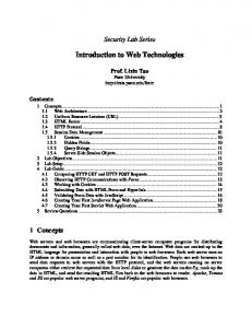


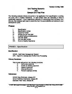


![[A Roadmap of Current Technologies and Future Trends] 1 Introduction](https://m.moam.info/img/260x300/a-roadmap-of-current-technologies-and-future-trend_598a24411723ddcd69889004.jpg)


