zadanych warunków eksperymentu, prędkość przemieszczenia 2000 mm/min, stanowi próg, powyżej którego niejednorodne pole temperatury może być ...
A
R
C
H
I
V
E
S
O
F
M
E
T A
L
L
Volume 57
U
R
G
Y
A
N
D
M
A T
E
R
I
2012
A
L
S
Issue 4
DOI: 10.2478/v10172-012-0124-2
M. MAJ∗ , W. OLIFERUK∗,∗∗
ANALYSIS OF PLASTIC STRAIN LOCALIZATION ON THE BASIS OF STRAIN AND TEMPERATURE FIELDS
ANALIZA LOKALIZACJI ODKSZTAŁCENIA PLASTYCZNEGO NA PODSTAWIE POLA ODKSZTAŁCEŃ I POLA TEMPERATURY
In the present paper the onset of plastic strain localization was determined using two independent methods based on strain and temperature field analysis. The strain field was obtained from markers displacement recorded using visible light camera. In the same time, on the other side of the specimen, the temperature field was determined by means of infrared camera. The objective of this work was to specify the conditions when the non-uniform temperature distribution can be properly used as the indicator of plastic strain localization. In order to attain the objective an analysis of strain and temperature fields for different deformation rates were performed. It has been shown, that for given experimental conditions, the displacement rate 2000 mm/min is a threshold, above which the non-uniform temperature distribution can be used as the indicator of plastic strain localization. Keywords: plastic strain localization, Strain field, Temperature field, Infrared thermography, Heat transfer
W niniejszej pracy początek lokalizacji odkształcenia plastycznego wyznaczono przy użyciu dwóch niezależnych metod bazujących na analizie pola odkształceń i pola temperatury. Pole odkształceń wyznaczono na podstawie przemieszczeń markerów zarejestrowanych przy użyciu kamery w świetle widzialnym. Jednocześnie, na przeciwległej powierzchni próbki wyznaczano pole temperatury przy użyciu kamery podczerwieni. Celem niniejszej pracy było określenie warunków, w których niejednorodny rozkład temperatury może być użyty, jako wskaźnik lokalizacji odkształcenia plastycznego. Aby osiągnąć postawiony cel, przeprowadzono analizę pola odkształceń i pola temperatury dla różnych prędkości deformacji. Pokazano, że dla zadanych warunków eksperymentu, prędkość przemieszczenia 2000 mm/min, stanowi próg, powyżej którego niejednorodne pole temperatury może być używane, jako wskaźnik lokalizacji odkształcenia plastycznego.
1. Introduction The deformation process, in both elastic and elastic-plastic regimes, was extensively studied by many researchers. Usually, the plastic deformation can be divided into two main stages. At first, the deformation is macroscopically uniform and then the strain localization appears. There are many experimental and theoretical works concerning localization phenomenon [1-11]. The strain localization takes place, when the different areas of specimen deform in different deformation rates. The localization phenomenon can be sudden and intense (L¨uders band propagation, shear bands propagation) or relatively slow as in case of diffuse necking (initially small and gradually increasing changes in strain rate). The onset of plastic strain localization can be determined on the basis of strain field; the non-uniformity of strain ∗ ∗∗
field can be used as an indicator of the onset of strain localization. On the other hand, the deformation process causes the temperature change of deformed material. This change is a macroscopic manifestation of a phenomena proceeding on the level of its microstructure. Thermal effects accompanying the elastic and elastic-plastic deformation were investigated by many researchers from different scientific centres in last years [12-23]. The rapid development of the infrared (IR) thermography, which is a contactless method of temperature measurement, caused an increase of number of papers concerning studies of these effects during both uniform and non-uniform deformation range. In these papers, the non-uniform temperature field is used as an indicator of plastic strain localization. Nevertheless, the most of deformation processes can not be treated as adiabatic
INSTITUTE OF FUNDAMENTAL TECHNOLOGICAL RESEARCH POLISH ACADEMY OF SCIENCES, WARSAW, POLAND BIALYSTOK UNIVERSITY OF TECHNOLOGY, BIALYSTOK, POLAND
1112 TABLE 1 Chemical composition of tested materials Chemical composition (wt. %) C
Mn
Si
P
S
Cr
Ni
W
Mo
Cu
V
Ti
Fe
Mg
Zn
Ti+Zr
304L
0.05
1.35
1.0
0.016
0.008
18.58
17.3
0.025
0.02
0.04
0.03
0.013
bal.
–
–
–
PA6
–
0.65
0.64
–
–
0.03
0.01
–
–
4.23
–
0.04
0.35
0.75
0.18
0.04
one, thus, it is necessary to take into account both the heat transfer within the specimen and the heat exchange between the specimen and the surroundings. Thus, the objective of this work is to specify the threshold above which, for tested materials and given experimental conditions, the non-uniform temperature distribution can be properly used as the indicator of plastic strain localization.
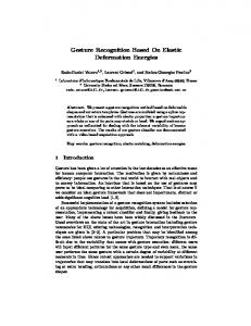
2. Experimental procedure 2.1. Specimen preparation The experiments were performed on austenitic stainless steel 304L and aluminium alloy (PA6) with chemical compositions shown in Table 1. The specimens were cut out from sheets using electro-erosion machining. The shape and dimensions of the specimen is presented in Fig. 1. Then, surface of the specimens were electro polished in order to obtain mirror-like, stress free surfaces. On the one side of the gauge part of the specimen a markers in form of dots were painted (Fig. 2). The other side was covered by soot to ensure high and uniform emissivity of the surface (soot emissivity ∼0.95).
Fig. 1. Shape and dimensions of the specimen
Fig. 2. Markers in form of dots placed on the one side of gauge part of the specimen
1113 2.2. Determination of strain and temperature fields Such prepared specimens were strained using MTS 858 testing machine with different displacement rates: 100 mm/min, 1000 min/mm and 2000 mm/min. There was no insulation between specimen and the grips. During straining the sequence of images was recorded using CCD visible light camera. On the basis of recorded sequence, the displacements of markers centres were determined. Knowing the initial distance between centres of dots l0 and current distance between the centres as a function of deformation time l (t), the local true strain ε (t) in tensile direction was calculated: ! l (t) ε (t) = ln . (1) l0 Simultaneously the opposite side of the specimen was observed using IR thermographic system and surface distribution of the temperature as a function of deformation time was recorded.
strain and temperature difference higher than 0.01 and 1◦ C, respectively, were assumed as indicators of plastic strain localization. It means that from that point the deformation starts to be non-homogeneous.
Fig. 3. Schematic diagram showing the position of markers for which true strain and mean temperature were determined
2.3. Determination of the onset of plastic strain localization
3. Results
On the basis of obtained strain and temperature fields the onset of plastic strain localization was determined. The analysis was limited to the markers laying on the specimen axis (Fig. 3). The strains ε (t) were calculated for each neighbouring dot centres as a function of deformation time. The mean temperature was calculated for all segments between centres of markers (see Fig. 3). Taking into account the accuracy of both methods (spatial resolution, thermal sensitivity, surface uniformity, etc.), the threshold values of true strain and mean temperature difference corresponding to the plastic strain localization were established. The values of true
On the basis of time dependences of strain and temperature, the onset of plastic strain localization was determined. In Figs.: 4a-6a the true strain vs. time dependences for austenitic steel strained at displacement rates: 100 mm/min, 1000 mm/min and 2000 mm/min, are presented. It is seen that initially the deformation is homogeneous and than different areas of specimen deform in different rates. The points lying in the area of strain localization deform much faster then that lying outside of the localized zone. In all figures the point where strain difference ∆ε is greater then 0.01 are marked as the onset of strain localization.
Fig. 4. The dependence of true strain a) and mean temperature b) vs. deformation time for austenitic steel strained at displacement rate 100 mm/min. The onsets of strain localization corresponding to ∆ε > 0.01 and ∆T > 1◦C are marked
1114
Fig. 5. The dependence of true strain a) and mean temperature b) vs. deformation time for austenitic steel strained at displacement rate 1000 mm/min. The onsets of strain localization corresponding to ∆ε > 0.01 and ∆T > 1◦C are marked
Fig. 6. The dependence of true strain a) and mean temperature b) vs. deformation time for austenitic steel strained at displacement rate 2000 mm/min. The onsets of strain localization corresponding to ∆ε > 0.01 and ∆T > 1◦C are marked
In Figs.: 4b-6b the mean temperature vs. time dependences for austenitic steel strained at same displacement rates are presented. As in case of strain vs. time dependence, the thermal response is initially homogeneous and then become non-homogeneous. In all figures the points, where the mean temperature difference ∆T is greater then 1◦C, are marked. On the basis of time corresponding to those points, the values of strain corresponding to the onset of strain localization were found from true strain vs. time dependence (see Figs.: 4a-6a). In Table 2 the comparison of strain values obtained using both methods is presented. It is seen, that for 100 mm/min the value of strain corresponding to the onset of plastic strain localization determined on the basis of strain field (∆ε > 0.01) is equal to 0.38, whereas that obtained using temperature field (∆T > 1◦C) is equal to 0.33 (see Fig. 4a and 4b). This means that, for this displacement rate the heat transfer within the specimen and the heat exchange between the specimen and the surroundings are significant and should not be neglected. In other words,
for these experimental conditions, non-uniform temperature distribution could not be used as an indicator of the onset of plastic strain localization. It is seen that the increase of displacement rate to 1000 mm/min is still not sufficient. In this case, obtained values of strain corresponding to the onset of strain localization for strain and temperature fields are equal 0.39 and 0.36, respectively (see Fig. 5a and 5b). The increase of displacement rate up to 2000 mm/min cause that results obtained using both methods are almost the same (see Fig. 6a and 6b). It means that the deformation process is carried out fast enough to neglect heat transfer within the specimen and between the specimen and the surroundings. In Figs.: 7-9 the true strain and mean temperature vs. time for aluminium alloy strained at displacement rates: 100 mm/min, 1000 mm/min and 2000 mm/min, are presented. In Table 3 the comparison of strain values corresponding to the onset of plastic strain localization, obtained using both methods are presented. It is seen that, as in case of austenitic steel, the non-uniform
1115 temperature distribution can be used as an indicator of plastic strain localization from displacement rate equal to 2000 mm/min.
TABLE 3 The comparison of strain values corresponding to the onset of plastic strain localization, obtained on the basis of strain and temperature fields for aluminium alloy
TABLE 2 The comparison of strain values corresponding to the onset of plastic strain localization, obtained on the basis of strain and temperature fields for austenitic steel
304L
Displacement rate [mm/min]
Onset of strain localization ∆ε > 0.01
Onset of strain localization ∆T > 1◦ C
100
0.38
0.33
1000
0.39
0.36
2000
0.39
0.39
PA6
Displacement rate [mm/min]
Onset of strain localization ∆ε > 0.01
Onset of strain localization ∆T > 1◦ C
100
0.15
0.12
1000
0.16
0.14
2000
0.15
0.15
Fig. 7. The dependence of true strain a) and mean temperature b) vs. deformation time for aluminium alloy strained at displacement rate 100 mm/min. The onsets of strain localization corresponding to ∆ε > 0.01 and ∆T > 1◦C are marked
Fig. 8. The dependence of true strain a) and mean temperature b) vs. deformation time for aluminium alloy strained at displacement rate 1000 mm/min. The onsets of strain localization corresponding to ∆ε > 0.01 and ∆T > 1◦ C are marked
1116
Fig. 9. The dependence of true strain a) and mean temperature b) vs. deformation time for aluminium alloy strained at displacement rate 2000 mm/min. The onsets of strain localization corresponding to ∆ε > 0.01 and ∆T > 1◦C are marked
4. Concluding remarks The onset of plastic strain localization was determined using two independent methods based on strain and temperature field analysis. Specimens were strained at different displacement rates: 100 mm/min, 1000 mm/min and 2000 mm/min, in order to find the limit, above which both methods give similar results. In other word, to find a limit when, the heat transfer within the specimen and between specimen and the surroundings can be neglected. It has been shown that initially the deformation is homogeneous and than become non-homogeneous. It has been shown that in case of both tested materials, the displacement rate 2000 mm/min can be treated as a limit, above which the non-uniform temperature field can be used as an indicator of plastic strain localization.
REFERENCES
[1] A.K. G h o s h, Metall. Trans. 5, 1607-1616 (1974). [2] P.V. M a k a r o v, Theor. Appl. Fract. Mec. 33, 23-30 (2000). [3] B. W a t t r i s s e, A. C h r y s o c h o o s, J.-M. M u r a c c i o l e, M. N e´ m o z - G a i l l a r d, Eur. J. Mech. A-Solid. 20, 189-211 (2001). [4] W.Y. C h i e n, J. P a n, S.C. T a n g, Int. J. Plasticity 20, 1956-1981 (2004). [5] F. L a g a t t u, J. B r i l l a u d, M.-C. Laf a r i e - F r e n o t, Mater. Charact. 53, 17-28 (2004). [6] J.J. L o p e z C e l a, I. M u n o z D i a z, Comput. Struct. 83, 1824-1833 (2005). [7] T.S. B y u n, N. H a s h i m o t o, Nucl. Eng. Technol. 38, 619-638 (2006).
Received: 10 May 2012.
[8] B. G u e l o r g e t, M. F r a n c o i s, C. V i a l - E d w a r d s, G. M o n t a y, L. D a n i e l, J. L u, Mat. Sci. Eng. A-Struct. 415, 234-241 (2006). [9] A. H o l g e r, Int. J. Plasticity 23, 789-840 (2007). [10] G. M o n t a y, M. F r a n c o i s, M. T o u r n e i x, B. G u e l o r g e t, C. V i a l - E d w a r d s, I. L i r a, Opt. Laser. Eng. 45, 222-228 (2007). [11] S.-H. T u n g, M.-H. S h i h, J.-C. K u o, Opt. Laser. Eng. 48, 636-641 (2010). [12] A. C h r y s o c h o o s, H. L o u c h e, Int. J. Eng. Sci. 38, 1759-1788 (2000). [13] H. L o u c h e, A. C h r y s o c h o o s, Mater. Sci. Eng. A-Struct. 307, 15-22 (2001). [14] B. W a t t r i s s e, J.-M. M u r a c c i o l e, A. C h r y s o c h o o s, Int. J. Therm. Sci. 41, 422-427 (2002). [15] W. O l i f e r u k, M. M a j, Mater. Sci. Eng. A-Struct. 387-389, 218-221 (2004). [16] B. Y a n g, P.K. L i a w, M. M o r r i s o n, C.T. L i u, R.A. B u c h a n a n, J.Y. H u a n g, R.C. K u o, J.G. H u a n g, D.E. F i e l d e n, Intermetallics 13, 419-428 (2005). [17] W. O l i f e r u k, M. M a j, Mater. Sci. Eng. A-Struct. 462, 363-366 (2007). [18] W. O l i f e r u k, M. M a j, Arch. Metall. Mater. 52, 2, 250-256 (2007). [19] B. B e r t h e l, A. C h r y s o c h o o s, B. W a t t r i s s e, A. G a l t i e r, Exp. Mech. 48, 79-90 (2008). [20] A. R u s i n e k, J.R. K l e p a c z k o, Mater. Design 30, 35-48 (2009). [21] O.A. P l e k h o v, O.B. N a i m a r k, J. Appl. Mech. Tech. Phy. 50, 127-136 (2009). [22] S. D u m o u l i n, H. L o u c h e, O.S. H o p p e r s t a d, T. B ˇr r v i k, Eur. J. Mech. A-Solid. 29, 461-474 (2010). [23] W. O l i f e r u k, M. M a j, R. L i t w i n k o, L. U r b a ń s k i, Eur. J. Mech. A-Solid. 35, 111-118 (2012).