1280x1024 Logarithmic Snapshot Image Sensor with Photodiode in Solar Cell mode Yang Ni New Imaging Technologies SA 1 Impasse de la Noisette, BP 426, 91370 Verrières le Buisson France TEL : +33 1 64 47 88 58
[email protected]
ABSTRACT The wide dynamic range and the contrast indexed imaging of logarithmic sensors have a great interest for a large variety of applications from digital photography to automatic machine vision. We have presented a 10um pitch 768x576 wide dynamic range sensor based on a logarithmic pixel design using photodiode in solar cell mode at IISW2011. This logarithmic pixel design has considerably improved the FPN and sensitivity compared to conventional logarithmic pixel designs. In this paper, we will present 1280x1024-pixel logarithmic snapshot mode image sensor with 6.8um pitch designed and realized in standard CMOS 0.18um 1P4M process.
1. Pixel Structure & Design As shown in Fig. 1, this logarithmic pixel design has followed solar cell photodiode mode logarithmic sensing technology developed at NIT. The snapshot function is realized by a simple in-pixel sample-hold circuit between the first and the second voltage follower amplifiers. The solar cell mode photodiode generates a negative voltage related to the substrate, the first voltage follower has to be able to sense this negative signal and translate it into a positive signal. We have developed several circuit structures capable to realize this function. In this design, a PMOS source follower has been used which is cable to translate linearly a negative voltage to positive one till -0.5V, enough for normal image purpose. The output of this positive image signal is sampled and held in a capacitor connected to a second source follower driving selectively the column bus. The total power consumption is less than 10nA per pixel, giving a moderate 10mA current drain for 1280x1024-pixel array. The parasite light sensitivity is of the key issue. This explains the reason that PMOS source follower has been used in pixel design. The NWELL of the PMOS transistors is used as parasite photo charge absorption sink. The sampling transistor, a NMOS, is placed between different NWELLs in order to be protected from diffusion charge. The obtained parasite light signal is under RMS noise level till 1000lux faceplate on the sensor which is acceptable for most of the machine vision applications. The drawback of this structure is the QE loss in near infrared spectrum. The noise source of the pixel comes mainly from solar cell photodiode and the sample-hold KTC noise. Due the absence of CDS on solar cell mode photodiode, the noise level is conditioned by the reset KTC noise in low light conditions and Johnson noise in high light conditions. The bandwidth limiting effect can reduce in some degree the Johnson noise in high light conditions. The global noise performance can be considered very modest in front of that obtained in true CDS based 4T pixel design.
2. Pixel Array Structure & Design The pixel array is arranged to receive all the control signals from horizontal direction and the power supply and biasing signals from the vertical direction. The output column bus is arranged in the vertical direction. The key design concern here is the crosstalk between these signals in the pixel array. Unlike charge mode pixel
design where no switching noise can be observed if the net capacitive current between the control signals is zero, the solar cell mode pixel design is more vulnerable to capacitive coupling noise because the image signal is sampled in voltage mode on a high impedance node. Fig. 2 shows the global structure of this sensor. This crosstalk issue is particularly critical during the global reset and sampling operations where 1.3 million pixels are switched at the same time as shown in Fig. 3. Several designs have been failed due to improperly designed control signal driving structures. The driving power of the control signals has to been carefully tuned in order to be strong enough when it is victim and to be weak enough when it is aggressor. We have used the current limited driver design by trimming the slew rate carefully. This current limited design guarantees the same slew rate for each control signal during the global operations and the line selected operations. The pixel array can be operated in 2 different modes: line by line rolling readout mode and sensingthen-readout mode. During the rolling readout mode, the sample signal is kept constantly on. The memory capacitor is used as a bandwidth limiting capacitor. Dual vertical row selection shift registers are used in order to control the effective exposure time by using a dummy reset on the photodiode. In snapshot mode, the pixel array is at first reset and then image is sampled into the memory capacitor at the same instant. Then one row is selected by the vertical shift register. A differential readout is made between the sampled image signal and then the re-sampled reset signal. This operation reduces considerably the fixed pattern noise. Dual analog line-buffers have been implemented on the bottom of the pixel array. One is scanned by the horizontal shift register during the other is loaded by the different readout from the pixel array. No dead time exists during the horizontal operation. The differential image signal is then amplified by a PGA of 0dB-12dB gain before sent to output pads. The maximum readout speed is limited to 80Mhz due to output buffer bandwidth. An external 14-bit ADC is used for digitalizing the image signal to digital form.
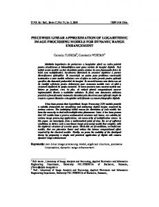
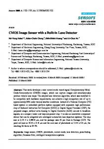
3. Characterization and Performance The sensor has been manufactured in a standard 0.18um CMOS process with 1P4M. A microlens array has been deposed on the CMOS wafer. Some fine-tuning work is still on the way. Fig. 4 shows a sample image of HDR scene. Table 1 summarized the basic characteristics of this sensor in snapshot mode. The photo response measured from the bare CMOS sensor is shown in Fig. 5. The logarithmic nature of the response is confirmed. Fig. 6 gives the RMS noise measured at 50Mhz pixel clock. Taking into account the 5fF (estimated value) for the photodiode and 10fF for the in-pixel memory capacitor, the RMS noise level should be around 1.2mV. The measured value is higher than this and the reason should be some KTC noise in the switched capacitor amplifier in the signal readout chain. Several other designs are under going including column based pre-amplification and column direct AD conversion. The FPN is given by Fig. 7 from 0 to 1000lux faceplate illumination. As shown in Fig. 8, the parasite light sensitivity has been measured under RMS noise till 1000lux faceplate, giving 38uV/lux*s. Special care has been taken in order to make this parasite light response in the same direction as the normal image response, so the black-Sun effect is not observable in this sensor. For a strong spot light, the pixel saturation does occur. By limiting the video amplifier excursion at 1V, the saturation occurs at 26K lux*s. So the normal outdoor use at even 25Hz is generally without problem with a fixed lens. The quantum efficiency still needs optimization. The photodiode made by using Nwell implant is not optimal. Fig. 9 gives the measured QE of this sensor (NSC1003) and one other NIT solarcell mode sensor
(NSC1005). There is a clear lose of QE in the visible range. We thought that this came from possible microlens focusing problem.
4. In-pixel motion detection function With logarithmic pixel design, the exposure time control is not needed, unlike a linear pixel design, the pixel signal can be saturated and not exploitable at the end of a frame if the exposure time is not adequate. The on-chip motion detection function can be easily realized by using this snapshot sensor. The control is the following: 1) read out the in-pixel memory content the first time; 2) sample the signal of the photodiode into the in-pixel memory and read out it the second, then reset the photodiode. By using the differential readout structure a frame-to-frame differentiated image can be obtained without any off-chip process. This function can be very useful in surveillance applications, 3D stereo vision, etc.
5. Conclusion This paper presents a 1280x1024-pixel logarithmic snapshot sensor based on NIT’s solar cell mode photodiode technology. This sensor demonstrates a precise logarithmic response with good uniformity over more than 120dB. The parasite light sensitivity has been measured at 38uV/lux*s. Due to the absence of CDS and charge transfer possibility, the noise performance is limited by the KTC/Johnson noise on the photodiode. Thanks to the ultra-wide dynamic range, this sensor can provide in-pixel motion detection without any external components and computations. This can be very useful in many smart sensing applications such as gesture control, surveillance etc. CMOS Process Pixel Array Size Pixel Size Pixel Dynamic Range Pixel Leakage Output Format Horizontal Clock Frequency Power Consumption Dark FPN Dark RMS noise Sensor Package
0.18um 1P4M Standard CMOS 1288x1032 pixels 6.8um > 120dB Under RMS noise level (1000 Lux faceplate) Analog differential > 80Mhz 50mA @ 3.3V 1.0mV 1.5mV CLCC-48
Table 1. Summary of the principle characteristics of the snapshot logarithmic mode sensor.
Figure 1. Structure of the snapshot mode logarithmic pixel based on solar cell mode photodiode.
Figure 2. Global structure of the 1280x1024 pixels snapshot mode logarithmic sensor.
Figure 3. Parasite capacitances which can influence the sample-hold operation in the pixel.
Figure 4. A sample raw image of high dynamic range scene captured by our snapshot mode logarithmic sensor.
Figure 5 Photoelectric response at 25ms @ 25°C (snapshot mode, bare silicon sensor).
Figure 6 Random noise at 25ms exposure time & 50Mhz pixel clock (snapshot mode, bare silicon sensor)
Figure 7 Fixed pattern noise at 25ms (snapshot mode, bare silicon sensor).
Figure 8. Shutter-closed-response at 50Mhz pixel clock.
Figure 9. Measured QE from this sensor (NSC1003) compared to one other NIT WDR sensor.