Our story begins ...
denotes a paragraph, and the (,) pair specify a hyperlink to a web page. When a web designer codes these HTML primitives, they know exactly what to expect from a human-computer interaction perspective. The problems with HTML are numerous, but one of the chief complaints is that it is inflexible with regard to the multiplicity of display devices that are on the market. A technique called Cascading Style Sheets (CSS) provides some relief by allowing one to have alternate display styles for hand held PDAs and desktops, but we’d like more flexibility in separating content from presentation. We would like to be able to use TITLE or AUTHOR instead of H1 and H2, for example, without explicitly defining how these will appear to the user. We want to define a semantic web (Berners-Lee, Hendler, and Lassila 2001). XML allows us to create tags such as , and is based on SGML (Standard Generalized Markup Language), which preceded it. Goldfarb (Goldfarb 1990) describes a language that originated prior to the web, and whose goals were generalized markup to satisfy a large number of typesetting requirements and devices. A language was needed to build upon the flexibility of SGML, without the presentational limitations of HTML and complexity of SGML, and this language evolved into XML. At first, one might question the purpose of XML, since it really is nothing more than tree-structured text. XML supports reading by both humans as well as computers, since its syntax is simple. Furthermore, XML suggests that application-specific areas of the web are not about documentation, per se, but about encoding information and knowledge. For example, CML (CML 2002) encodes the atomic structure of molecules. How they molecules appear to the user may depend on a wide variety of factors, but by standardizing on CML, users can take
XML
XML, eXtensible Markup Language, emerged in the mid 90s as a new language for the Web. To see why it emerged, we need to begin with a look at the ubiquitous HTML (HyperText Markup Language). HTML is a tag-based ASCII language for defining content on the web. In HTML, one can define both text and graphics-based markup in the form of
617
Fishwick
PHOTO (JPEG)
SG (SVG)
render
geometry
LIGHTBULB (MXL) dyn-fsm1
dyn-fsm5 dyn-fsm3
dyn-fsm2
FSM-1D (MathML)
dyn-fsm4
FSM-3Dprim (X3D)
FSM-2D (SVG)
FSM-3Dagent (X3D)
FSM-3Dpipe (X3D)
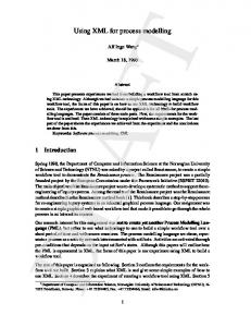
Figure 1: Semantic Network of Lightbulb System Models
and ON. OFF-UNPLUGGED is the state where there is no applied power, whereas OFF is the state once the power is applied, and yet the switch activated by a pull-cord remains in the off-position. ON is the state when the switch is turned on. Consider Figure 1, which defines a semantic network expressing several model types. This figure is a graphical realization of an equivalent RDF (Framework 2002), which specifies an XML framework for specifying ontologies. A computer graphic 2D rendering, or photograph, yields the model in the upper left of Fig. 1. Labeled, PHOTO, this is a kind of model of the lightbulb system, since it presents some visual aspects of the system. Likewise, the more geometrically-oriented SG in the upper-right of Fig. 1, is short for Scene Graph, and shows a scene graph specifying the lightbulb’s geometric structure. The acronym to the left of the parentheses in Fig. 1 specifies the name of a model, and the one inside the parentheses, defines the file type (JPEG for the PHOTO, and SVG for SG). The models below LIGHTBULB are all ones associated with the dynamics of the lightbulb. These dynamics are captured as a 3 state FSM whose states are those previously mentioned. The model may be presented as 1D, 2D, or
advantage of tools that import and export CML as a fundamental data type. Likewise, MathML (MathML 2001) defines the content of mathematical expressions independent of presentation. Both SGML and XML bear striking resemblance to many other markup languages, such as LATEX with the primary difference being that the former are meant for generalized markup of information, and so create the possibility of communicating and dispersing and managing general semantic content throughout the web. 4
MODEL CUSTOMIZATION
I will overview the architecture of the rube Project, but first, let’s discuss the nature of modeling so that we can gain a foothold in our search for new modeling techniques. Modeling is the act of choosing materials in such a way as to capture some aspect of a target scene or object. For simulation, this aspect is one of dynamics. We seek to capture concepts of state, event, and time in the model that we craft. Let’s suppose that the object of interest is a lightbulb, and that we wish to capture a simple behavior dictated by state transitions: OFF-UNPLUGGED, OFF,
618
Fishwick 3D objects, and moreover, the presentations may be customizable so that one may both encode and view the FSM as flowing water between tanks (FSM-3Dpipe) or an avatar moving between gazebos (FSM-3Dagent). An important aspect of Fig. 1 is that all of these models can be viewed as styles generated from the core MXL file, to be discussed in Sec. 5.3. This results in a unique philosophical view of model specification and presentation: namely, that the core specification in MXL is largely independent of how the models are presented. This view, or perspective, promotes personalization and customization of the modeling interface, allowing for both native and artificial cultural adaptations to the way in which models are experienced. 5
RUBE PROJECT
5.1 Architecture rube is a project that has engaged us for the past two years, as a follow on to our work in multimodeling and web-based modeling and simulation. The purpose of rube is to facilitate dynamic multimodel construction and reuse within a 3D, immersive environment. Within the context of Modeling and Simulation (M&S), this project reflects a “next generation” philosophy about modeling (Fishwick 2002). The project is vast in scope, but focused on this purpose. We began work in rube using the Virtual Reality Modeling Language (VRML) as our primary vehicle for specification of both geometry and dynamics. VRML is the current ISO standard for 3D graphics on the web. This was done by using the “Prototype” extensiblity mechanism of VRML. In the past year, however, we have progressed toward XML as a way to declare model and presentation semantics. Figure 2 displays the structure of rube. We begin with two files: scene and model. The scene file contains visual objects and components that are presentations of corresponding formal dynamic model equivalents in the model file. Thus, the model file captures the topology of the dynamic model, whereas the scene file captures what the components and connections “look like.” This can be taken further by considering senses other than vision, but since vision is our primary apparatus for interacting with the world, we built rube with the idea of viewing models in 1D, 2D, or 3D. By “1D,” I am referring to a textual, or typographical, presentation.
Figure 2: rube Architecture
ing objects over time. X3D contains primitives such as cone, cylinder, and sphere, as well as more flexibile geometric structures such as NURBS (Non-Uniform Rational B-Splines), and polygonal meshes. SVG contains similar 2D geometries. Presentation in 1D involves languages such as HTML, XHTML (an XML version of HTML), and MathML. The following is an excerpt from an X3D file:
5.2 X3D We have been using two scene languages, one of which is denoted in Fig. 2: X3D. X3D, or eXtensible 3D, is the follow-on standard to VRML. The 2D scene language, other than X3D, is SVG (Scalable Vector Graphics). Both SVG and X3D support internal scripting in Javascript and Java so that the scenes can be made dynamic with mov-
619
Fishwick
All semantics for the FSM are encoded in Javascript (.js suffix) files. The MXL file is translated into DXL (next section) using XSLT (XML Style Sheet Transformation). XSLT provides a sophisticated pattern language for transforming one XML document into another document, often in either XML or XHTML. The translation is most generally accomplished using a network or pipe containing a series of transformations, capable of efficiently and easily modifying documents.
The file, like all XML files, is ASCII and describes a scene graph (Foley, van Dam, Feiner, and Hughes 1999). A scene graph is a tree of transform nodes ending in leaf nodes, which define the individual pieces of geometry needed to create the whole after working recursively upward through the hierarchy. This graph defines the visualization of one red sphere of FSM-3Dprim from Fig. 1.
5.4 DXL 5.3 MXL After specifying the scene and model files in Fig. 2, then rube begins its processing. The first step is to generate a DXL (Dynamics eXchange Language) file. While the structure of MXL contains model-specific element and attribute names, DXL serves as an assembly layer, with a small number of components. The DXL file contains blocks, each having input and output ports and optional local variables. Blocks are tied together using connectors. An excerpt from the DXL file generated from the MXL file in Sec. 5.3 follows:
Given a desired appearance in Sec. 5.2, we can define the formal structure using MXL (Multimodeling eXchange Language) of the lightbulb 3 state FSM. The following is an excerpt from the complete MXL file:
DXL translates directly into Java or Javascript using DOM (Domain Object Model). DOM is the way in which programs can externally access the internal XML tree from outside.
620
Fishwick DOM allows code to traverse the tree using pattern-matching based on the XPATH specification. The code is augmented by SimPackJ/S, which is a Java/Javascript version of SimPack.
The robustness of the system will be tested this Fall 2002, with the first use of rube by students in the undergraduate and graduate simulation classes. As part of our work in the three-year old Digital Arts and Sciences curricula, we also plan to employ rube as a way to not only rephrase and represent dynamic model structures, but also static structures, such as simple mathematical formulae cast in MathML. The idea of customization and personalization of model structure naturally lends itself to the Arts, and so this activity helps to form a bridge between the Colleges of Fine Art and Engineering. We need to continue our work at the architectural level or rube, to support XML as a fundamental data type, and to ensure that DXL is robust enough to serve as the foundation for future model types. We also need to make it possible for individual styles to be semi-automatically generated directly from MXL. To date, one must create both the scene and model files, without any help from rube. Next year, we hope to have a system in place, which in combination with XSLT, will permit styles to be more easily specified. Finally, we need to create more substantial, applied model structures with rube, since most of our present work is in making the system operational.
5.5 Model Fusion Given the original scene graph and the Java or Javascript created from DXL, we are in a position to merge these two to create a scene graph with embedded code. This is then placed into a browser and the user engages and navigates the scene using the interactivity afforded by the code. The last three snapshots in the bottom-right part of Fig. 1 illustrate 3D scenes containing interactive FSM models. 6
CONCLUSIONS
A preliminary observation is one concerning XML. Its definition and use are bound to have dramatic effects on modeling and simulation, with rube serving as one type of system which uses XML as a core language. Using XML in the core has advantages and disadvantages. The advantages that I’ve overviewed include the separation of content from presentation, and XML’s prominence in the web community; it is here to stay around for a long time, or evolve into something even more powerful and flexible. The disadvantages of using XML are in sacrificing some speed gained through more proprietary interfaces, and in not knowing which XML document types will be around long enough to use. Like the field of computer science, in general, XML is a very fast moving target if one strays into various types, powerful as they may be. Document types progress in stages from notes to working drafts, candidate and proposed recommendations, and finally W3C recommendations. So, there is the uncertainty associated with the acceptance stage, but reaching the final stage is no guarantee of permanence. Summarizing the paper, our team has constructed a basic XML-based modeling and simulation system that serves all four multimodeling assumptions presented in Sec. 2. The software is not yet complete since we still need to test the basic model types, and provide new ones such as Petri Nets and System Dynamics graphs. In the simulation classes at the University of Florida, we have conducted surveys to determine the relative effectiveness of allowing students the ability to choose their own presentations, not only for the system being modeled, but the model as well. Students have overwhelmingly voted highest for the ability to customize model structures, while noting the inherent inefficiencies in constructing 3D models. We see the majority of efficiency problems as being addressable by technology advancement as hardware gets cheaper and faster, and yet much remains in creating more accessible 3D modeling programs. 3D is still fraught with the usual problems of navigation and selection.
ACKNOWLEDGMENTS I would like to thank the current students on the rube Project: Taewoo Kim, Minho Park, Jinho Lee, and Hyunju Shim, and graduated students Robert Cubert, John Hopkins, and Linda Dance. Work on rube is supported by the Air Force Research Laboratory under Grant F30602-01-1-0592, and the National Science Foundation under grant EIA-0119532. REFERENCES Berners-Lee, T., J. Hendler, and O. Lassila. 2001. The Semantic Web. Scientific American 284 (5): 34–43. CML 2002. Chemical Markup Language. [accessed July 3, 2002]. Consortium, W. W. W. 2002. [accessed July 3, 2002]. Fishwick, P. A. 1991. Heterogeneous Decomposition and Coupling for Combined Modeling. In Proceedings of the 1991 Winter Simulation Conference, ed. W. D. Kelton, G. M. Clark, and B. L. Nelson, 1199 – 1208. Piscataway, New Jersey: Institute for Electrical and Electronic Engineers. Fishwick, P. A. 1992. Simpack: Getting Started with Simulation Programming in C and C++. In Proceedings of the 1992 Winter Simulation Conference, ed. R. C. Crain, J. R. Wilson, J. J. Swain, and D. Goldsman. Piscataway, New Jersey: Institute for Electrical and Electronic Engineers.
621
Fishwick Fishwick, P. A. 1995. Simulation Model Design and Execution: Building Digital Worlds. Prentice Hall. Fishwick, P. 1996. Web-Based Simulation: Some Personal Observations. In Proceedings of the 1996 Winter Simulation Conference, ed. D. T. Brunner, J. J. Swain, J. M. Charnes, and D. J. Morrice, 772–779. Piscataway, New Jersey: Institute for Electrical and Electronic Engineers. Fishwick, P. 2002. Next Generation Modeling: A Grand Challenge. In Proceedings of the 2002 Western Simulation Multiconference, 25–30. San Antonio, TX. Foley, J. D., A. van Dam, S. Feiner, and J. F. Hughes. 1999. Computer Graphics: Principles and Practice in C. 2 ed. Addison-Wesley. RDF 2002. Resource Description Framework. [accessed July 3, 2002]. Goldfarb, C. F. 1990. SGML Handbook. Oxford University Press. MathML 2001. Mathematical Markup Language. [accessed July 3, 2002]. Page, E., A. Buss, P. Fishwick, K. Healy, R. Nance, and R. Paul. 2000. Web-Based Simulation: Revolution or Evolution? ACM Transactions on Modeling and Computer Simulation 10 (1): 3–17. Tiller, M. 2001. Introduction to Physical Modeling with Modelica. Kluwer International Series in Engineering and Computer Science. Zeigler, B. P., H. Praehofer, and T. G. Kim. 2000. Theory of Modeling and Simulation: Integrating Discrete Event and Continuous Dynamic Systems. Academic Press. AUTHOR BIOGRAPHY PAUL FISHWICK is Professor of Computer and Information Science and Engineering at the University of Florida. He received the Ph.D. in Computer and Information Science from the University of Pennsylvania in 1986. His research interests are in computer simulation, modeling, and animation, and he is a Fellow of the Society for Computer Simulation (SCS). Dr. Fishwick served as General Chair for WSC 2000 in Orlando, Florida. He has authored one textbook, coedited three books and published over 100 technical papers. His email address is , and his home page is .
622