INTERNATIONAL JOURNAL OF CIRCUITS, SYSTEMS AND SIGNAL PROCESSING
Volume 8, 2014
3D Graph-based Vision-SLAM Registration and Optimization Doaa M. A.-Latif, Mohammed A.-Megeed Salem, H. Ramadan and Mohamed I. Roushdy
between the previously known features and the newly measured ones. The environment representation is another important challenge. The robot has to represent its surrounding environment in a way that is easily processed and updated and in the same time it should be informative and capture as much information as possible of the surrounding environment.
Abstract—Mapping and localization of robots in an unknown environment is a complicated but essential task for navigation and further operations. This has made researchers eager to solve this problem and accordingly many techniques have been investigated using different types of sensors. In this paper we address the Simultaneous Localization and Mapping (SLAM) problem using colored and depth images. We present an overview of the most known techniques with focus on the graph-based mapping, along with a comparison of different algorithms used in registration and optimization. The system is tested on a standard 3D datasets of indoor environment.
This paper presents an extended survey of current state-ofthe-art of techniques used for vision-based SLAM for indoor environment. We present focus on the graph-based map registration and optimization [34]. The rest of the paper is organized as follows. In the following section II we discuss the different types of sensors used for SLAM and we justify the advantage of optical sensors over the other types. Section III provides an overview of the different SLAM processing techniques along with a survey of the related work. The tested methods are presented in section IV. Results are detailed and discussed in section V, followed by conclusion in section VI.
Keywords—Graph SLAM, Optimization, Registration, RGB-D sensor, Kinect.
I. INTRODUCTION
R
have a great impact on our life, they have many forms and are used everywhere, they can be found in automotive, medical, manufacturing and space industries. The nature of the robot operation scenario requires that it builds a map of the environment and at the same time localize itself in this map. The problem becomes hard if the operating robot is mobile autonomous in an unknown environment. However, localization is needed for environment mapping, and available maps are necessary for self localization. This problem is known as Simultaneous Localization and Mapping (SLAM). In the localization task the robot assumes it has a map of the environment and that it only has to answer the question, where am I? In the mapping task it assumes that its exact location is known and that it only has to answer the question; what does the world look like? OBOTS
II. SENSING Various type of sensors has been used to generate 3D Maps. Classical examples include, laser [1][2], stereo cameras [3][4][31][32] monocular cameras [5][6][7][30], and recently RGB-D sensors[9][10][8]. The type of sensor used affects how the data is processed and the information in the generated map greatly. A robot is usually equipped with internal sensors that are used to perceive its position, pose and motion parameters. The main internal sensors are odometry and compasses. Compasses are often used to detect headings of mobile robots. Odometry estimates the robot's trajectory from the summation of wheel speeds; it is widely used for localization. Internal sensors can provide inaccurate data so they are always used with some other type of sensor to correct the drifts, there are even some approaches that don't use the internal sensors at all.
The SLAM problem can be adapted and combined with other techniques to solve many problems in different domains including the medical one. It can have a great impact on the visually impaired if used to provide a description of the environment and an independency in navigation especially if used in indoor environments. The mapping task is very challenging because usually the data provided by the sensors are noisy and sometimes they interfere with the map updating process resulting in false matches
Laser range finder is traditional sensor which is widely used in robotics. It uses a laser beam to measure the distance to an object. They produce 3D point clouds that are suitable for frame-to-frame alignment and for dense 3D reconstruction but the produced point clouds are not as rich in visual information as the ones produced by color cameras moreover they are bulky and expensive compared to cameras.
All the authors are affiliated with the Faculty of Computer and Information Sciences, Ain Shams University Abbassia 11566, Cairo, Egypt. Emails:
[email protected];
[email protected];
[email protected];
[email protected]
ISSN: 1998-4464
Cameras can be used to reconstruct a depth map from at least two images showing a 3D scene from different 123
INTERNATIONAL JOURNAL OF CIRCUITS, SYSTEMS AND SIGNAL PROCESSING
observation points. They have become more and more important in the robotics field, due to its remarkable characteristics such as low cost, small size, low weight and low energy consumption. Unfortunately when it comes to 3D mapping it requires extensive processing to extract dense depth information from color cameras data alone, especially in indoor environments with very dark or sparsely textured areas.
Volume 8, 2014
between the two poses. These transformations are either odometry measurements between sequential robot positions or are determined by aligning the observations acquired at the two robot locations. Once the graph is constructed the optimization process starts to find the configuration of the robot poses that best satisfies the constraints. Graph-based SLAM contains two chore tasks:
RGB-D cameras are sensing systems that capture RGB images along with per-pixel depth information. They rely on either active stereo or time-of-flight sensing to generate depth estimates at a large number of pixels. The most well-known RGB-D camera is the Microsoft Kinect [11]. They provide an alternative to the expensive and bulky Laser range finders. It provides 3D point clouds with depth information and at the same time captures rich visual information of the environment. It also gives a means to create maps of an environment with known scale (most camera-based visual mapping algorithms can only create maps with unknown scale). The Microsoft Kinect is able to grab RGB images of 640x480 pixels. It has a frame rate of 30Hz and an angular field of view of 57 degrees horizontally and 43 degrees in the vertical axis and the depth sensor range is between 1.2m and 3.5m. RGB-D sensors provide a trade of between accuracy and complexity. They provide rich visual scenes when compared to laser sensors and at the same time simplify the calibration and rectification processes when compared to monocular or stereo cameras.
1.
Graph construction concerned with constructing the graph from the raw sensor measurements.
2.
Graph optimization concerned with determining the most likely configuration of the poses given the edges of the graph.
The process is summarized graphically in Fig. 1. The graph construction is usually called front-end and it is heavily sensor dependent, while the second part is called back-end usually it relies on an abstract representation of the data.
III. SLAM PROCESSING PARADIGMS There have been many approaches to solve the SLAM problem, most of which can be categorized into two main paradigms: filtering and optimization based approaches [12]. A. Filtering approaches The most popular filtering approaches are the extended Kalman filter (EKF) and particle filters. EKF were used in [13][14][15][33], it stores the robot pose and the environment feature positions in one state vector and uses an error covariance matrix to store the uncertainties of these state estimates along with cross correlation terms between features and poses. Particle filters were used in [16][17][18]. It maintains multiple map hypotheses, each conditioned on a stochastically sampled trajectory through the environment.
Fig. 1 The front-end and back-end of the SLAM process.
There have been many successful approaches to the visual SLAM problem using the RGB-D sensor. In [10] a hand held approach uses 3D point clouds provided by an RGB-D sensor. The frontend relies on Speeded up robust features (SURF) for feature extraction and matching and then the location is estimated using RANdom SAmple Consensus (RANSAC). The generated map is refined using Hierarchical Optimization for Pose Graphs on Manifolds (HOGMAN). In [9] followed the same path but with some changes, scale invariant feature transform (SIFT) are used to align consecutive data frames then RANSAC and an RGBD-Iterative closest point (ICP) algorithm is used for refining the alignment. This new variant of ICP combines shape and visual information for scan alignment. The SIFT features, verified with RANSAC, act as an initialization for ICP, which reduces the computation time. The Tree-based network optimizer (TORO) was used for global optimization in a graph-based SLAM technique. This approach makes a new addition when compared to the previous ones by using surface elements (SURFELS). The
Filtering approaches were used widely over the past years due to the fact that the data provided by the robot sensors suffer from noise and inconsistency and these approaches can model different sources of noise and their effects on the measurements. B. Optimization-based approaches Optimization (Graph)-based approach usually uses an underlying graph structure to represent the robot measurements. The graph nodes represent the robot poses and the measurement acquired at this position and the edges represent a spatial constraint relating two robot poses. A constraint usually consists of the relative transformations ISSN: 1998-4464
124
INTERNATIONAL JOURNAL OF CIRCUITS, SYSTEMS AND SIGNAL PROCESSING
Volume 8, 2014
to adjust the accumulative error and align the complete data sequence.
SURFELS reduce the generated map size by a factor of 32 and present a better map quality for viewing, but unfortunately they affect the computation time preventing the whole system from operating in real time. In [8] a graph-based SLAM system is built using the oriented FAST and rotated BRIEF (ORB) as a feature detector and descriptor. The poses were calculated using RANSAC and further refined using the Generalized Iterative Closest point (GICP). Finally global optimization was achieved using the General (Hyper) Graph Optimization g2o.
A. SLAM Front-end The SLAM front-end consists of two parts the Registration and the Loop closure. 1) Registration The registration step to align consecutive data frames. The alignment is usually done by estimating an approximate transformation between the consecutive frames and then refining this initial estimate. The approach used in this study is similar to the one presented in [4]. It can be summarized into 3 main steps:
IV. GRAPH-BASED SLAM The approach used to complete this study follows the related work presented above. Fig. 2 provides an overview of the system. In the front-end the graph is constructed as the camera moves, new areas are discovered and new poses are added to the graph. When adding a new pose registration is required to align the data together. After a while small errors in registration accumulate resulting in inconsistency in the generated map. This is obvious if the robot visited a previously
1.
Computing the correspondence between successive frames: Find 2D feature correspondence between RGB Images. b) Reject bad correspondence. c) Transform the 2D features to their equivalent 3D features.
2.
Estimate the initial alignment of the frames.
3.
Refine the alignment.
First step we applied four combinations of feature detectors and descriptors: 1.
Speeded Up Robust Features (SURF) [35].
2.
Features from Accelerated Segment Test (FAST) [36] & Binary Robust Independent Elementary Features (BRIEF)[37].
3.
Oriented FAST and Rotated BRIEF (ORB)[38].
4.
Binary Robust (BRISK)[39].
Invariable
Scalable
Keypoint
These were used to detect and describe the features in the RGB images obtained from the Kinect device. Then after matching the corresponding features we rejected the bad correspondences using the symmetry test and the fundamental matrix. The symmetry test is so simple features are matched from the first image to the second image i.e for every detected feature in the first image find its possible match in the second image. Then the features are matched from the second image to the first image i.e for every detected feature in the second image find its possible match in the first image, and finally the two matching lists are compared and the non-symmetric items are rejected.
Fig. 2 An overview of the used system.
mapped place, the error will result in presenting the same place twice in the map. Here comes the need for the back-end
ISSN: 1998-4464
125
INTERNATIONAL JOURNAL OF CIRCUITS, SYSTEMS AND SIGNAL PROCESSING
The fundamental matrix is a 3 × 3 matrix. It is the algebraic representation of epipolar geometry, It relates the corresponding points between two stereo images xi↔x'i. If a point in space is viewed in one image as xi and in the second as x'i, the two points will be related together with the fundamental matrix x'iFT xi = 0. The fundamental matrix F transforms the point xi in an image into an epipolar line l' = Fxi in the second image. For each point xi in one image, there exists a corresponding epipolar line l' in the other image. Any point x'i in the second image matching the point xi must lie on the epipolar line l'.
Rnew
Find the centroids of both point clouds A,B.
2.
Translate both point clouds to the origin then find the optimal rotation (R) using (SVD).
3.
Combine R and the centroids into a single 4x4 transformation matrix.
Registration between successive clouds produce satisfactory results but for only small or moderate distances, as noise and errors in depth values and in pair-wise cloud alignment cause the estimated pose to drift over time resulting in an erroneous map. This is obvious when a long path is mapped, eventually returning to a previously visited location. The cumulative error in cloud alignment results in a map that has two representations of the same region in different positions. This is known as the loop closure problem. Loops are represented as edges between nodes that are not temporally adjacent. Once a loop is detected the new correspondence between nodes can be used as an additional constraint in the graph. Fig. 3 shows an example. The question now is how to detect the loop in an efficient way. There has been many loop closing techniques presented in the literature and according to [22] they can be classified into 3 main categories.
1 N i (2) PA N i 1 To find the optimal rotation we first re-center both point clouds so that both centroids are at the origin. This removes the translation component, leaving only the rotation to deal with, after that we calculate H, and using SVD to find the rotation N
[U , S ,V ] SVD( H )
(4)
R VU T
(5)
i 1
1.
Map to map as the name indicates this is used in approaches that depends on building small sub-maps of the environment, the correspondence between submaps is investigated taking into account the visual appearance and the relative position between the submaps.
2.
Image to map the most recent image captured is compared with the built map features looking for correspondence. The pose of the camera is determined relative to a map of point features by finding correspondences between the image and the features in the map.
Then combine the rotation and centroids in one matrix
1 0 CA 0 0
ISSN: 1998-4464
0 1 0 0
0 0 centroid A 1 0 1
(7)
2) Loop closure
centroid A
(3)
0 0 0 1
Third we refine the alignment between registered point clouds, Iterative Closest Point (ICP) was used to minimize the alignment difference. Since its introduction in [19] there has been many variants introduced affecting each step in the algorithm. ICP starts with two point clouds and an initial guess for their relative transformation, and iteratively refines the transformation by repeatedly generating pairs of corresponding points and minimizing an error metric. It terminate when the change in the mean square error falls below a pre-set threshold. The Generalized iterative closest point (GICP) is one of many variants of the ICP algorithm [20]. GICP introduces a change in the last step of standard ICP, which is the error minimization function. It attaches a probabilistic model to it and keeps the rest of the algorithm unchanged so as to reduce complexity and maintain speed. Correspondences are computed using Euclidean distance and kd-trees are used in the look up of closest points.
The centroids are just the average point and can be calculated as follows: x (1) P y z
H ( PAi centroid A )( PBi centroid B )T
R 0 0 0
And the rigid transformation matrix T is calculated as T=CBRnewCA.
Second we estimated an initial rigid transformation (rotation and translation) that will align the points in the first point cloud to the second point cloud using Singular Value Decomposition which can be summarized in 3 steps: 1.
Volume 8, 2014
(6)
126
INTERNATIONAL JOURNAL OF CIRCUITS, SYSTEMS AND SIGNAL PROCESSING
3.
Volume 8, 2014
Image to Image the correspondence is investigated between images of the world being mapped; the most recent image is compared with previously captured images looking for matches.
Fig. 4 Checking for closing a loop when reaching a node with a pose close to an existing one. Fig. 3 An additional constraint is added to the graph.
The goal of a maximum likelihood approach is to find the configuration of the nodes x that minimizes the negative log likelihood F(x) of all the observations
In our approach a simple image to image loop detection approach is used. A set of key nodes is stored with the features detected and described in the registration step are kept for each key node. When a new observation is processed its location is examined if it is close to any of the key nodes it is further checked Fig. 4 shows an example if the number of matches passes a certain threshold in our case 40 features then this node is considered as a loop closing node and a constraint represented as an edge is added to the graph connecting the two matched nodes.
F ( x)
eijT ij eij i , j C
(8)
Fij
where C is the set of pairs of indices for which a constraint (observation) z exists. This means that we tries to find the solution to x* arg min F ( x) (9) x
The function value of F(x) at the minimum is not important, what matters is the value of the variable x* where that minimum occurs, further details about graph optimization in SLAM can be found in [12] [23].
B. SLAM back-end The SLAM back-end role is to optimize the map reducing the error by optimizing the underling graph structure provided by the front end, this graph is composed of n vertices storing the observation at certain poses, and edges representing the neighbour relations between these poses. Global optimization techniques try to estimate optimally all poses to build a consistent map of the environment. It can be considered as choosing the best solution that minimizes an error function from all the feasible solutions.
In our study we have compared the performance of 3 different global optimizers:
If we assume that X = ( x1, ... , xn )T is a vector describing the robot poses where xi describe the pose of node i and Zij is the mean and Ωij is the information matrix of the transformation matrix that aligns the observation at node i and node j together. Let ẑ (xi , xj) be the estimated measurement at nodes xi and xj The log likelihood lij of zij can be calculatedas lijα [zij T Ẑ(xi , xj) ] Ωij [zij - Ẑ(xi , xj) ]. If we consider e(xi , xj) as an error function that computes the difference between the estimated measurement ẑij and the real measurement Zij such that eij (xi , xj) = zij - Ẑ(xi , xj).
ISSN: 1998-4464
127
1.
Georgia Tech Smoothing and Mapping: Known also as GTSAM [26]. It is a C++ library based on factor graphs. A factor graph consists of factors connected to variables. The factors represent probabilistic information on the unknown random variables in the estimation problem.
2.
Hierarchical Optimization on Manifolds: Known also as HOG-Man [24] it applies Gauss-Newton with sparse Cholesky factorization that considers a manifold representation of the state space to better deal with the camera rotations.
3.
General (Hyper) Graph Optimization: Known also as g2o [25]. It is a C++ framework for performing the optimization of nonlinear least squares problems that can be embedded as a graph or in an hyper-graph.
INTERNATIONAL JOURNAL OF CIRCUITS, SYSTEMS AND SIGNAL PROCESSING
Volume 8, 2014
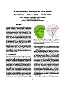
Fig. 5 The color and depth images of the Freiburg1_room dataset image courtesy to the CVPR group [29].
The following open source projects were used to implement different techniques subject to our comparison: The point cloud library (PCL) [27] was used in the transformation estimation and refinement. It is a large scale, open source project for 2D/3D image and point cloud processing, the Open source computer vision library (OpenCV) [28] which has been used in feature detection, description and matching. The different algorithms used in this comparison were tested on the Computer vision and pattern recognition group (CVPR) [29] datasets. These datasets contain the color and depth images of a Microsoft Kinect sensor along with the ground-truth trajectory. Fig. 5 provides an example of the data provided by the Kinect in the Freiburg1_room dataset.
Fig. 7 The resulting map of Freiburg1_room dataset without loop closure and global optimization.
Fig. 8 The resulting map after processing the first 150 image sequence in the Freiburg1_room dataset.
Fig. 6 Average percentage of good matches on the 4 tested datasets.
V. RESULTS
In the registration module we have tested the feature correspondence step by combining different detectors and descriptors. We calculated the percentage of good matches by counting the number of matches after rejecting bad correspondence with the fundamental matrix. Fig. 6 shows the result. All the tested algorithms produce close results between 40%-60% with BRISK getting the most scores on all the datasets tested. Details of the tests results were presented in our earlier work [21].
All the tests were performed using an Intel Core i7-3610QM CPU @ 2.30GHz _ 8 running a 32 bit Linux 3.2.0. We used four of the CVPR group [29] datasets in our tests: Freiburg2_xyz which contains data for debugging translations where the Kinect was moved along the principal axes in all directions, Freiburg2_desk which captures the details of a typical office scene with two desks, a computer monitor, keyboard, phone, chairs, etc. with the Kinect moving around two tables so that the loop is closed, Freiburg1_room which has been recorded through a whole office environment and is well suited for evaluating how well a SLAM system can cope with loop-closures, and Freiburg2_pioneer slam which was recorded from a Kinect mounted on top of a Pioneer robot which was joysticked through a maze of tables, containers and other walls, so that several loops have been closed for map building. ISSN: 1998-4464
We have used the CVPR group evaluation tools to compare the global optimization algorithms. Two error metrics have been used: the Absolute Trajectory Error (ATE), and the Relative Pose Error (RPE). The ATE is useful for measuring the performance of visual SLAM systems. It measures the absolute trajectory error by comparing the difference between 128
INTERNATIONAL JOURNAL OF CIRCUITS, SYSTEMS AND SIGNAL PROCESSING
the estimated and the ground-truth path after associating them using the timestamps. It also computes the mean, median and the standard deviation of these differences. The RPE is useful for measuring the drift of visual odometry systems. It computes the error in the relative motion between pairs of timestamps. More details about the evaluation metrics are in [29].
Volume 8, 2014
Fig.7 shows the results of registering consequent data without loop closure and global optimization as explained above small errors in registration accumulate over time resulting in an incorrect representation of the environment. Fig.8 shows the effect of loop closure constraints and global optimization algorithm in correcting the drifts in the map. The evaluation results of the Freiburg1_room dataset are presented, the ATE results are detailed in Table 1 and the RPE in Table 2. The difference between the estimated trajectory and the ground-truth using g2o as an optimizer can be viewed clearly in Fig.9. The average error on the tested four datasets is described in Table 3 in which all three produce similar scores but g2o performs slightly better.
VI. CONCLUSION In this paper a description of the graph-based approach using a RGB-D camera as its only sensor was presented. Our system factored the SLAM problem into front-end and the back-end providing a comparison of different registration and global optimization techniques using a standard dataset. The SLAM problem has a long history with many approaches but yet there are still some open problems including solving SLAM for extended periods or life-long SLAM. We have also started investigation in Multi-robot cooperation in map building using multiple sensors each exploring a different part of the environment [40].
Fig. 9 The result trajectory compared to the groundtruth of the Freiburg1_room dataset using g2o.
Table 1 The Absolute Trajectory Error on the Freiburg1_room dataset in meters. ATE GTSAM HOG-Man g2o rmse mean median std min max
0.083895 0.074727 0.069797 0.038135 0.015323 0.156559
0.079756 0.070692 0.065114 0.036927 0.010718 0.163685
REFERENCES [1]
0.079022 0.068790 0.064971 0.038891 0.009273 0.154001
[2]
[3]
Table 2 The Relative Pose Error on the Freiburg1_room dataset. RPE GTSAM HOG-Man g2o Relative Translation Error Relative Rotation Error
0.089116
0.077349
0.078440
4.346548
3.628420
3.773067
[4]
[5]
[6]
Table 3 The Average Absolute Trajectory Error and Relative Pose Error on the tested four datasets. Average rmse GTSAM HOG-Man g2o Absolute trajectory error Relative Translation error Relative Rotation error
ISSN: 1998-4464
0.158508 m
0.160902 m
0.157364 m
0.109753 m
0.085200 m
0.081775 m
2.436107 deg
5.969135 deg
4.279843 deg
[7]
[8]
129
I. Dryanovski, W. Morris, and Jizhong Xiao. Multi-volume occupancy grids: An efficient probabilistic 3d mapping model for micro aerial vehicles. In International Conference on Intelligent Robots and Systems (IROS), 2010 IEEE/RSJ, pages 1553–1559, 2010. William Morris, Ivan Dryanovski, and Jizhong Xiao. 3d indoor mapping for micro-uavs using hybrid range finders and multi-volume occupancy grids. In RSS 2010 workshop on RGBD: Advanced Reasoning with Depth Cameras, Zaragoza, Spain, 2010. Christopher Mei, Gabe Sibley, Mark Cummins, Paul Newman, and Ian Reid. RSLAM: A System for Large-Scale Mapping in Constant-Time Using Stereo. International Journal of Computer Vision, 94(2):198–214, June 2010. David Schleicher, Luis M. Bergasa, Manuel Ocana, Rafael Barea, and Elena Lopez. Realtime hierarchical stereo Visual SLAM in largescale environments. Robotics and Autonomous Systems, 58(8):991–1002, August 2010. Pierre Lothe, Steve Bourgeois, Fabien Dekeyser, Eric Royer, and Michel Dhome. Monocular SLAM Reconstructions and 3D City Models: Towards a Deep Consistency. Computer Vision, Imaging and Computer Graphics. Theory and Applications, pages 201–214, 2010. Mohammed A-Megeed Salem Multi-Stage Localization Given Topological Map for Autonomous Robots. In The 8th IEEE International Conference on Computer Engineering and Systems (ICCES12), November 27-29, 2012, Cairo, Egypt. Sara Elgayar, Mohammed A.-Megeed Salem, and Mohamed I. Roushdy. Two-level topological mapping and localization based on sift and the wavelet transform. In 2nd International Conference on Circuits, Systems, Communications, Computers and Applications, Dubrovnik, Croatia, June 25-27 2013. M. Algaba, JL. Blanco, and J. Gonzalez. Desarrollo e implementacion de un metodo de generacion de mapas 3d usando el sensor Kinect. Master’s thesis, Higher Technical School of Computer Science Engineering, MAPIR Group, System Engineering and Automation Department, University of M´alaga, mar 2012.
INTERNATIONAL JOURNAL OF CIRCUITS, SYSTEMS AND SIGNAL PROCESSING
[9]
[10]
[11] [12] [13] [14]
[15]
[16]
[17]
[18]
[19]
[20] [21]
[22]
[23]
[24]
[25]
[26]
[27]
[28] [29]
[30]
[31]
[32]
Peter Henry, Michael Krainin, Evan Herbst, X. Ren, and D. Fox. RGBD mapping: Using depth cameras for dense 3D modeling of indoor environments. In the 12th International Symposium on Experimental Robotics (ISER), 2010. Nikolas Engelhard, F. Endres, J. Hess, J. Sturm, and W. Burgard. Realtime 3D visual SLAM with a hand-held RGB-D camera. In Proceedings of the RGB-D workshop on 3D perception in robotics at the European robotics forum, Vasteras, Sweden, number c, 2011. Microsoft Kinect.2010. [Online]. Available:http://www.xbox.com/enUS/Kinect. N Sunderhauf. Robust Optimization for Simultaneous Localization and Mapping. PhD thesis, Technische Universitat Chemnitz, 2012 J Nieto, T Bailey, and E Nebot. Recursive scan-matching SLAM. Robotics and Autonomous Systems, 55(1):39{49, January 2007. Abdelkrim Nemra and Nabil Aouf. Robust Airborne 3D Visual Simultaneous Localization and Mapping with Observability and Consistency Analysis. Journal of Intelligent and Robotic Systems, 55(45):345-376, January 2009. Piotr Skrzypczyski. Simultaneous localization and mapping: A featurebased probabilistic approach. International Journal of Applied Mathematics and Computer Science, 19(4):575{588, December 2009. Arturo Gil, Oscar Reinoso, M_onica Ballesta, and Miguel Julia. Multirobot visual SLAM using a Rao-Blackwellized particle filter. Robotics and Autonomous Systems, 58(1):68{80, January 2010. Giorgio Grisetti, Cyrill Stachniss, and Wolfram Burgard. Improved Techniques for Grid Mapping With Rao-Blackwellized Particle Filters. IEEE Transactions on Robotics, 23(1):34-46,February 2007. V. Pradeep, G. Medioni, and J. Weiland. Visual loop closing using multi-resolution SIFT grids in metric-topological SLAM. 2009 IEEE Conference on Computer Vision and Pattern Recognition, pages 14381445, June 2009. P. Besl and N. McKay, “A method for registration of 3-D shapes,” IEEETransactions on pattern analysis and machine intelligence, vol. 14, no. 2, pp. 239–254, 1992. Segal, D. Haehnel, and S. Thrun, “Generalized-icp,” in Proc. of Robotics: Science and Systems (RSS), vol. 25, 2009, pp. 26–27. Doaa M. A.-Latif, Mohammed A.-Megeed Salem, H. Ramadan, and Mohamed I. Roushdy. Comparison of 3d feature registration techniques for indoor mapping. In 8th IEEE International Conference on Computer Engineering and Systems (ICCES), November, 2013. Brian Williams, Mark Cummins, Jose Neira, Paul Newman, Ian Reid, and Juan Tardos. A comparison of loop closing techniques in monocular SLAM. Robotics and Autonomous Systems, 57(12):1188–1197, December 2009. Giorgio Grisetti, Rainer Kummerle, Cyrill Stachniss, Wolfram Burgard. A Tutorial on Graph-Based SLAM. IEEE Intelligent Transportation Systems Magazine,, 52(3):199–222, 2010. Giorgio Grisetti, R Kummerle, Cyrill Stachniss, Udo Frese, and Christoph Hertzberg. Hierarchical optimization on manifolds for online 2d and 3d mapping. In IEEE International Conference on Robotics and Automation (ICRA), pages 273– 278. IEEE, 2010. Rainer Kuemmerle, Giorgio Grisetti, Hauke Strasdat, Kurt Konolige, and Wolfram Burgard. g2o: A general framework for graph optimization. In Proc. of the IEEE Int. Conf. on Robotics and Automation (ICRA), 2011. F. Dellaert and M. Kaess. Square Root SAM: Simultaneous Localization and Mapping via Square Root Information Smoothing. The International Journal of Robotics Research, 25(12):1181–1203, December 2006 R. B. Rusu and S. Cousins, “3D is here: Point Cloud Library (PCL),” 2011 IEEE International Conference on Robotics and Automation, pp. 1–4, May 2011. “Open source computer vision (opencv),”[Online].Available: http://opencv.org/ J. Sturm, N. Engelhard, F. Endres, W. Burgard, and D. Cremers, “A benchmark for the evaluation of RGB-D SLAM systems,” in Proc. of the International Conference on Intelligent Robot Systems (IROS), 2012 A Cumani,., S Denasi,., A Guiducci,., and G Quaglia,. Integrating monocular vision and odometry for SLAM. WSEAS Transactions on Computers, 3(3), 625-630. (2004). A Cumani,., , S Denasi., A Guiducci,., and , G Quaglia. Robot localisation and mapping with stereo vision. WSEAS Transactions on Circuits and Systems, 3(10), 2116-2121. 2004 A Cumani., and A GuiducciMobile robot localisation with stereo vision. In Proceedings of the 5th WSEAS International Conference on Signal
ISSN: 1998-4464
[33]
[34]
[35] [36] [37]
[38]
[39]
[40]
Volume 8, 2014
Processing, Computational Geometry & Artificial Vision (pp. 176-181). September 2005 T Neuzil. Simultaneous mapping and navigation for skid steered mobile robot. In Proceedings of the 7th WSEAS International Conference on Signal Processing, Robotics and Automation (pp. 93-98). February 2008 Doaa M. A.-Latif, Mohammed A.-Megeed Salem, H. Ramadan, and Mohamed I. Roushdy. Comparison of optimization techniques for 3d graph-based slam in 4th European Conference of Computer Science (ECCS ’13), Paris 2013 H. Bay, T. Tuytelaars, and L. V. Gool, “Surf Speeded up robust features,” Computer Vision ECCV 2006, 2006. E. Rosten and T. Drummond, “Machine learning for high-speed corner detection,” Computer VisionECCV 2006, pp. 1–14, 2006. M. Calonder, V. Lepetit, C. Strecha, and P. Fua, “Brief: Binary robust independent elementary features,” Computer Vision- ECCV 2010, pp.778–792, 2010. E. Rublee, V. Rabaud, K. Konolige, and G. Bradski, “Orb: An efficient alternative to sift or surf,” in Computer Vision (ICCV), 2011 IEEE International Conference on, 2011, pp. 2564–2571. S. Leutenegger, M. Chli, and R. Y. Siegwart, “BRISK: Binary Robust invariant scalable keypoints,” 2011 International Conference on Computer Vision, pp. 2548–2555, Nov. 2011. Doaa M. A.-Latif, Mohammed A.-Megeed Salem, H. Ramadan, and Mohamed I. Roushdy " On 3D Map Alignment For Multi-Robot Visual SLAM" Industry Academia Collaboration (IAC) Conference Egypt 2014.
Doaa M. A.-Latif is a teaching assistant at the faculty of Computer and Information Sciences, Ain Shams University in Cairo, Egypt since 2010. She was born in Cairo and received her B.S. degree in 2009 in Computer Science and currently she is working on her M.S. degree. Her research interest include: Robot Vision, Image processing, Multimedia. Mohammed A.-Megeed Salem is an Assistant Professor in the faculty of Computer and Information Sciences, Ain Shams University in Cairo, Egypt since 1999. He was born in Cairo. He received his B.S. degree in 1997 in Mathematics and Computer Science. In 2002 he received the M.S. degree in Scientific Computing from the Ain-Shams University in Cairo. In November 2008 he received the PhD degree from the Humboldt-Universitaet in Berlin, Germany in Multiresolution Image Segmentation. His research interests include: Robot Vision, Multimedia, Signal Processing, Multiresolution Analysis, and Wavelet Transform. H. Ramadan is professor of physics and vice dean of the Faculty of Computer and Information Sciences, Ain Shams University, Cairo, Egypt since 2013. Mohamed I. Roushdy received his Ph.D. in 1993, M.Sc degree in 1984 and B.Sc. degree in 1979 from Faculty of Science; Ain Shams University and Experimental doctoral research work was conducted at Bochum University in Germany, 1989-1991. He is a Professor of computer Science since 2007 and Dean of the Faculty of Computer and Information Sciences, Ain Shams University, Cairo, Egypt since 2010. His areas of research are artificial intelligence, image processing, data mining and expert systems.
130