Keywords: Multi-Terrain; Mobile Robot Platform; Modular; Reconfigurable. ... This work is funded under Uniten Seed Fund project â Development of Advance ...
DEVELOPMENT OF MULTI-TERRAIN MOBILE ROBOT PLATFORM BASED ON MODULAR CONCEPT JEFFREY TAN TOO CHUAN1, ADZLY ANUAR1 and IZHAM BIN ZAINAL ABIDIN2 1
Department of Mechanical Engineering 2
Department of Electrical Engineering Mobile Robotics Group College of Engineering Universiti Tenaga Nasional
Abstract
Keywords: Multi-Terrain; Mobile Robot Platform; Modular; Reconfigurable.
The various geographical topographies in Malaysia have urged the study of multi-terrain platform for remote operating vehicle development. Numerous products have been introduced by western countries but lack in performance due to the natural geographical differences in design specifications. Apart from cost consideration, the need of local study is essential in order to produce an efficient platform to meet the local requirements. An effective all-terrain design will serve as a platform for further remote operating vehicle.
In this work, the main objective is to study the development of multi-terrain mobile robot platform with modular design concept. The overall design reference is based on conventional tank-treaded design due to the well-known multi-terrain capability. The general design is being localized to accommodate off-the-shelf materials and small scale manufacturing techniques in order to minimize the development cost. Before hardware implementation, a full scale CAD model has been developed in order to go through the analysis and optimization process.
Conventional monolithic robotics construction needs a vast investment due to the rigid design. Modular design has the advantages of lower production cost due to the generalize structure and re-configurability. In this study, the main locomotion system design has been generalize into smaller sub-system in order to develop into identical module. This module has the capability to produce various distinguish configurations by different arrangement of the
modules. Hence, the modular design can act as a rapid prototyping platform to provide various different configurations for multi-terrain mobile robot study.
Introduction
The main objective of this work to develop a multi-terrain mobile robot platform based on modular concept. As a continuous work from previous project [1], tank-treaded design has been selected with the enhancement of modular concept in this work. The main advantage is the recofigurability for rapid prototyping. The mechanical design starts from a full scale CAD model creation to optimize the design before hardware implementation. On the other hand, the electronics and control development focus on advance line following system. The multiterrain capability enables the platform for more advance outdoor applications in the future development.
Design Specifications and Parameters
This work is funded under Uniten Seed Fund project – Development of Advance Line Follower Robot System. But the design specifications are set to fulfill a more challenging working environment instead of typical indoor controlled environment in order to ready for future outdoor development of the project. Besides that it is also following the design requirements from a robotics event in RoboFest – Survival Robot [2] as part of project evaluations. The robot dimension is limited to 300 x 300 x 300 mm and with a weigh no more than 12 kg. The robot needs to be capable to overcome a few expected “obstacles”, which are 25 mm height bumper, grass surface, 22o ramp, tunnels, and vibrating surface.
Figure 1: Mechanical Structure Design Specifications
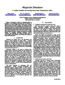
The fundamental design concept is based on the conventional tank-treaded design due to the success of similar design concept in a previous project, Autonomous Personal Mobile Robot System for Land Mines Detection on Uneven Terrain [ ]. The design had been proven having 1
capability to overcome rough uneven terrain. As a continuous work, the new design has improved certain weaknesses from the previous attempt. One of the main enhancements is the integration of modular design concept to improve the hardware flexibility.
Figure 2: “Seeker” from the Autonomous Personal Mobile Robot System Project
Modular Design Concept
The main limitation of the Seeker design in the previous attempt is the rigid mechanical structure. The design has minimum dimension expandability to accommodate various components for different applications. Reconfigurability is one of the main advantages of modular design. It allows rearrangement of the elemental unit to form new hardware configurations for the different needs in different applications. Besides that, modular design can shorten development time and the module is easily replaceable in case of failure [3].
Figure 3: Driving System Module
In this work, one side of the driving system has been packaged into a single module. In this module, it is equipped with the pulley system and the driving belt. A DC motor is attached to drive the system. Two of the identical modules have been produced. Few possible configurations are illustrated on the figure below.
Figure 4: Hardware Configurations with 2 Modules
CAD Design and Modeling
The whole system is being model using CAD software, Pro/Engineer. The design started with the pulley system. It consists of 2 driving pulleys on the upper part and 2 support pulleys in the lower part of the driving belt. One of the driving pulleys is driven by the DC motor which is directly attached at the side. The whole system is being accommodated by U shape plate housing. The housing is equipped with various mounting points for base plate installation and also sensor placements. This design allows rapid prototyping and reconfigurabilty in the overall system development.
Figure 5: CAD Model of the Module
Hardware Implementation
Figure 6: Driving System Module Components Arrangement
The pulley system is made by Polyethylene (PE) timing pulleys. All the pulleys are belong to standard industrial H type timing pulley (Pitch: ½”) which the driving pulley having 17 teeth and the support pulley having 10 teeth. The belt is the classical synchronous belt with the same pitch length and width of 38.1 mm. All the pulleys are supported by bearing to reduce rotational friction and power loss.
Figure 7: Driving Pulleys
Figure 8: Support Pulleys with Bearing
Steel plate has been chosen to construct the housing to provide a sturdy structure for the module. The plate is cut using CNC machine and bent into U channel. The steel plate is chromed as the finishing to prevent corrosion.
Figure 9: Steel Plate Housing
One important design on the housing is the slots for the rear driving pulley (without DC motor attached). The pulley is supported by the flanged bearings which are secured on the slots. The slot design enables the belt to be tensioned by adjusting the placement of the pulley along the slots.
Figure 10: Slot Design to Tension the Rear Driving Belt
Electronics, Sensory and Control System
Motors The motor selected for the system is the VEXTA 15W DC Motors with motor driver cards. This motor operates at 24V DC, with an operating torque from 0.4lb/inch to an excess of 260 lb/inch, depending upon the sizes of the motor.
The supplied motor card has the ability to control the basic movements of the motor via logic signals which makes it very versatile for microcontroller control applications. The controller card is also equipped with a speed feedback and speed control facilities which rely on voltage signals given to the motor card. Apart from that, the motor card would also have a built in manually controlled speed selector.
Sensors with Slave Controller The sensors used for the slave controller consist of the ultra bright red LED combined with a light dependent resistor (LDR). Although there are other sensors that can be used which would give higher flexibility and dependability such as machine vision system, but these sensors are expansive. Therefore, a low cost but popular alternative choice would be the LED-LDR combination sensors.
In terms of the colours chosen for the LED, based upon literature done [4], it can be seen that red would be the best choice due to its high spectral intensity as compared to other colours. The basic line sensor circuit would be as shown in the figure below.
Figure 11: Basic Line Sensor Circuit
Based upon the figure, the output of sensor circuit could either be logic high or logic low depending upon the condition whether the sensor senses a line or not. However, the circuit shown would require the user to repeatedly tune the circuit when there is a different ambient light condition. Apart from that the threshold level between line and no line is very fine as such that different ambient light condition would affect its performance.
However, for the robot, a new breed of tune-able sensors were introduced which is based upon direct sensor reading. This type of sensors would require the use a microcontroller (PIC16F688) to do onboard processing after which the result of it is conveyed to the master controller. The advantage of having this facility would improve the flexibility of the sensor if applied to a different controller in the future. Apart from that it would reduce computing burden onto the master controller. Figure below shows the actual circuit used for the system.
Figure 12: Robot Sensor Arrangements
Master Controller The Master controller functions as the main controller which oversees the general function of the robot. By having a master controller instead of a conventional single controller would increase the master controller availability to cater for any robot functionalities. For line following applications, the microcontroller chosen is the PIC16F877 manufactured by Microchip Inc. The rational behind this is simply because that the PIC is easily obtainable with a reasonable cost incurred.
Figure 13: The Master Controller with the DC Motor Card Connected
Control System - General Line Tracking Capability The algorithm downloaded into the master controller will actually process sensor reading received by the slave controller and use it to navigate around a predetermined track. Apart from that, the master controller should be able to do speed control, junction counting sequence and also 90o turns, all dependent upon the type of program downloaded. The general flow chart employed into the master controller is as shown in figure below.
Figure 14: General Flowchart of the Line Following Robot
Conclusions
Figure 15: Multi-Terrain Mobile Robot Platform
The mobile robot platform has been developed based on the modular concept. The CAD model has been fully hardware implemented and assembled to form the driving system module. Various configurations have been tested to accommodate different systems and applications. The platform works well with the line following control system. Outdoor applications are yet to be tested to evaluate the multi-terrain capability.
References [1] Adzly Anuar, Salman Yussof, Ismail Said, Jeffrey Tan Too Chuan, “The Development of an Autonomous Personal Mobile Robot System for Land Mines Detection on Uneven Terrain”, Advanced Technology Congress 2003, Putrajaya [2] http://www.robofest.org.my/uploaded/rules/Survival/survivalspec.htm, Survival Robot – Robot Specification, 2004 [3] Uwe D. Hanebeck, Nihad Šaldic, Günther Schmidt, “A Modular Wheel System for Mobile Robot Applications”, Proceedings of the 1999 IEEE/RSJ, International Conference on Intelligent Robots and Systems, 1999 [4] Ashari, S., “Line, Gap and Colour Sensors”, in Dept of Electrical Engineering, 2004, University Tenaga Nasional: Malaysia. p. 70