Dec 3, 1990 - We present a simple bent-beam PIC algorithm. Using this .... 4 BENT-BEAM ALGORITHM .... A. T. Drobot, J. W.-K. Mark, and D. E. Nielsen, Jr.
© 1992 Gordon and Breach Science Publishers, S.A.
Particle Accelerators, 1992, Vols. 37-38, pp. 131-139 Reprints available directly from the publisher Photocopying permitted by license only
Printed in the United Kingdom
3D PARTICLE SIMULATION OF BEAMS USING THE WARP CODE: TRANSPORT AROUND BENDSt ALEX FRIEDMAN, DAVID P. GROTE, DEBRA A. CALLAHAN and A. BRUCE LANGDON Lawrence Livermore National Laboratory, Livernl0re CA 94550, USA.
IRVING HABER U.S. Naval Research Laboratory, Washington DC 20375, USA. (Received 3 December 1990)
WAR P is a discrete-particle simulation program which was developed for studies of space-chargedominated ion beams. It combines features of an accelerator code and a particle-in-cell plasma simulation. The code architecture, and techniques employed to enhance efficiency, are briefly described. Current applications are reviewed. In this paper we emphasize the physics of transport of three-dimensional beams around bends. We present a simple bent-beam PIC algorithm. Using this model, we have followed a long, thin beam around a bend in a simple racetrack system (assuming straight-pipe self-fields). Results on beam dynamics are presented; no transverse emittance growth (at mid-pulse) is observed.
INTRODUCTION In a Heavy Ion inertial confinement Fusion (HIF) driver, space-charge-dominated beams are to be accelerated and transported over large distances. WARP1,2 is a discrete-particle simulation program developed specifically for the study of emittance growth resulting from the nonlinear self-fields of such beams. In the sections below, the code's architecture is reviewed, and its numerical methods (which have been described previously) are summarized. Some of the applications of the code are then reviewed. The new bent-beam algorithm currently in use is described, and some early results presented. Although somewhat preliminary in nature, these simulations suggest that it is possible to transport a space-chargedominated beam around a fairly sharp bend without inducing unacceptable emittance growth. Finally, some directions of our ongoing research are indicated.
t Work performed under the auspices of the U.S. Department of Energy by Lawrence Livermore National Laboratory under contract W-7405-ENG-48, and by the U.S. Naval Research Laboratory under Lawrence Berkeley Laboratory contract DE-AC03-76SF0098. 131
A. FRIEDMAN et al.
132
2
CODE OVERVIEW
The WARP code contains a number of distinct parts, including: a 3d particle-in-cell (PIC) package, WARP6, which uses a "warped Cartesian" mesh to describe bends; an r,z (axisymmetric) PIC package, WARPRZ; an envelope-equation solver (used for particle loading and lattice testing); and facilities for initialization, diagnostics, etc. In this paper we focus exclusively on WARP6. The code has been built up from independent modules; each can be loaded and used as a code by itself. This is made possible through the facilities of BASIS, 3 which provides a development system and an interactive user interface. WARP runs on Cray computers and on Sun workstations. The simulation takes place in the laboratory frame. The computational mesh fills a moving window and is laid down anew at each timestep. The self-field is electrostatic in the beam frame. At present (slow beams), we use these fields directly. For faster beams we will obtain the lab-frame self-E and B via a Lorentz transformation. Self-field boundary conditions are those of a square metal pipe in x,y; a round pipe is an option. Periodicity of the electrostatic potential ¢ in z is assumed; this is reasonable provided the beam does not approach the ends of the mesh, or is itself assumed periodic. The algorithm for the self-field conserves axial momentum algebraically; energy is not identically conserved, but is instead used as a check on the accuracy of the calculation. The envelope solver is used for particle loading, since it is important to be able to initialize a beam which is approximately "matched"; it is also useful for the initial testing of an accelerator lattice specification. It is necessary to follow beams over long distances, and 3d simulations are computationally challenging. Therefore, efficiency was a critical element of the code's design and has been obtained via a number of means, summarized here. In leapfrog motion, if a particle were to land within a sharp-edged focusing or bending element on four steps while its neighbor did so on only three, they would receive dramatically different impulses. Thus, the advance is modified to incorporate "residence corrections" for element forces; these take into account the fraction of the velocity advance step actually spent within the element. This allows much bigger steps than otherwise would be possible. No mesh arrays for the electric field components are used; instead, ¢ is gathered from cells in the neighborhood of each particle, and then differenced on a particleby-particle basis. This saves the space of three 3d arrays. The FFT field-solver is fully vectorized and uses no scratch space. The particle advance is vectorized. Deposition of the charge density p is vectorized with length 8, over cells overlapped by each particle.
3
SUMMARY OF APPLICATIONS
In addition to the bent-beam modeling described herein, current studies include the following areas; some of these are described elsewhere, and are merely noted:
3D PARTICLE SIMULATION USING WARP
3.1
133
Drift Compression.
Drift compression is current enhancement resulting from ahead-to-tail velocity gradient or "tilt". We are examining this process, as well as the effects of quadrupole magnet misalignments on it. Relatively small misalignments can, depending .on how they are phased with respect to each other; lead to significant off-axis displacements. Image forces and fringing fields can then induce emittance growth. 4 A goal of this work is to gain an understanding of how rapidly the beam may be compressed without unacceptable emittance degradation. The early stages of this work have been described previously.2
3.2
Equilibration.
We are examining processes that lead to the transfer of thermal energy between transverse and longitudinal motions. WARP simulations indicate that, for certain ranges of physical parameters (phase advance, etc.), a beam initialized colder in z than in x,y will heat rapidly in z until T z is a large fraction of T x,y' In one such test, described previously,2 a periodic beam was followed for 150 full focusing-defocusing (FODO) lattice periods (9000 steps). The beam had a phase advance per cell of a o == 60°, depressed to a == 20° by space charge. It was initially cold longitudinally. A rapid conversion of transverse thermal energy into longitudinal thermal energy at the beginning of the run (growth rate on the order of 1/10 of the plasma frequency, cop)was followed by a slower collisional phase, during which T z and Tx,y rise together. We have run many simulations to demonstrate that numerical artifacts are not a likely source of the heating. It has been observed over significant ranges of numerical and physical parameters (including runs with meshes which resolve the initial axial Debye length), and in finite-length beams. Furthermore, it disappears for certain ranges of physical parameters, in particular when cop is reduced sufficiently, e.g., a == 45°. Such axial heating might arise from a mechanism analogous to an anisotropy-driven "Harris" mode in a magnetized plasma. 5 Previous researchers· have noted collective equilibration mechanisms (in other geometries).6,7 We also have made a preliminary observation of rapid equilibration in an axisymmetric beam, using WARPRZ. The equilibration issue is of interest because it is important to identify in advance all constraints on driver design. For present driver designs, equality of T z and Tx,y is acceptable, but a significantly greater thermal spread in z might make final focus problematic. As driver parameters evolve it may be desirable to revisit this issue.
3.3
Axial Confinement and Nature of Equilibria.
To follow a finite-length beam for a long time, it is necessary to apply an axial confining force; without it the beam will blow apart electrostatically. Considerable work has been done on this subject, and we have had success in modeling axially confined beams that remain "quiescent" over the entire run. We have followed beams for up to 175 lattice periods without significant numerical emittance degradation. This work is described in a companion paper. 8
A. FRIEDMAN et al.
134
3.4
Longitudinal Stability With Nonzero Gap Impedance.
This work is being carried out using WARPRZ, and is described in a companion paper. 9
4
BENT-BEAM ALGORITHM
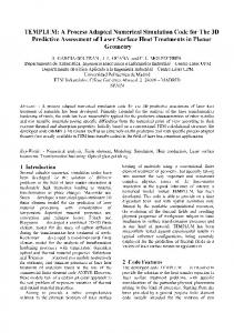
We have developed a family of techniques for modeling bends. These are based upon following a particle's position and velocity in a sequence of rotated inertial (laboratory) frames. In the "exact" method (not yet in WARP), no pseudo-forces are used. The scheme conserves phase-space area identically, and implies no large-aspect-ratio (gentle bend) expansion. We have formulated 3d and 2d (transverse) algorithms of this type. 1 0 In this paper, we concentrate upon the "simplified" method, which is now in use. The method is inexact, but is accurate enough for our present purposes. It folds the velocity rotation part of the coordinate transformation into the physical dipole field as a "pseudo-gyrofrequency." Minor changes to the position advance are also needed. "Intermediate" methods are also possible, and in fact may be optimal for many purposes. The radius of curvature of the reference orbit (usually the vessel centerline) is r*. Time is the independent variable for particle orbits. The conventional (for accelerator codes) independent variable s is, in WARP, a dependent variable for orbits, as are the transverse coordinates x,y. In the straight sections, s == z, while in the bends, s == -r*8. The "radial" coordinate is x == r - r*; the unit vectors x and s evolve as a particle moves, and are different for each particle. This geometry is depicted in Figure 1(a). The axial speed is V z == - reo The axial position (projection onto the centerline) is advanced in time using (1)
In this derivation of the simplified bent-beam algorithm, we show that the necessary "pseudo-forces" are equivalent to a velocity rotation. The radial coordinate increases for an unaccelerated particle due to "centrifugal force"; with q/m == 1:
d -Vx
dt
==
v2 _z_
r*
+x
+ {E + v x B)x.
(2)
For the "Coriolis force," use conservation of angular momentum: (3)
After algebra: (4)
3D PARTICLE SIMULATION USING WARP
135
centerline
y
/
vessel
wall (a)
'nilialV
(b)
effect of B + ~.~s~e~uuduo~-
ef~ctof
~~ n alone
~
FIGURE l(a) Geometry of the bent-beam algorithm. (b) Effect of folding the pseudo-gyromotion into the bending field.
Note there is no factor of two in the Coriolis force because the frame of reference differs from that in the classical analysis; particle velocities retain their laboratoryframe magnitudes. Considering only the "pseudo-force" terms, the rate of change of the velocity angle is consistent with the requirement iJ = - vz/r: z -d arctan (V- x ) = -V . dt Vz ~ +x
(5)
The transformation is a pure rotation; one can readily verify that dlvl/dt = O. Implementation in WARP was straightforward. We needed only to augment the dipole (bending) field with a "pseudo-gyrofrequency":
By,
dipole