scaffolds are then registered using a modified graduated as- signment graph ... Fourth, due to the lack of a surface representation â since only sample points ...
3D Shape Registration using Regularized Medial Scaffolds Ming-Ching Chang
Frederic F. Leymarie
Benjamin B. Kimia
LEMS, Division of Engineering, Brown University Providence, RI 02912, U.S.A. mcchang,leymarie,kimia @lems.brown.edu �
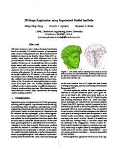
Abstract This paper proposes a novel method for global registration based on matching 3D medial structures of unorganized point clouds or triangulated meshes. Most practical known methods are based on the Iterative Closest Point (ICP) algorithm, which requires an initial alignment close to the globally optimal solution to ensure convergence to a valid solution. Furthermore, it can also fail when there are points in one dataset with no corresponding matches in the other dataset. The proposed method automatically finds an initial alignment close to the global optimal by using the medial structure of the datasets. For this purpose, we first compute the medial scaffold of a 3D dataset: a 3D graph made of special shock curves linking special shock nodes. This medial scaffold is then regularized exploiting the known transitions of the 3D medial axis under deformation or perturbation of the input data. The resulting simplified medial scaffolds are then registered using a modified graduated assignment graph matching algorithm. The proposed method shows robustness to noise, shape deformations, and varying surface sampling densities.
Figure 1: The medial scaffold matching of two scans of David’s head [13] result in a global registration. Matching scaffold curves are shown in identical colors; one dataset is shown with red dots, and the other with blue dots.
are the most common form of 3D input data from modern scanning technologies, such as laser sensing and Computer Tomography (CT). The local registration problem has been considered extensively in the past twenty-five years, and a good survey can be found in [5], while more recent work can be found, e.g., in the proceedings of the 3D Digital Imaging and Modeling Conference series [12]. Most local registration techniques are variants of the well-known Iterative Closest Point (ICP) algorithm, originally proposed by Besl and McKay [2], known to share many problems commonly associated with local search techniques. First, it is sensitive to local extrema, with immediate consequence that when the initial pose is relatively different from the optimum or when multiple nearby local extrema exist, the algorithm may not converge to the correct solution. Second, it is sensitive to noise and may converge slowly if the noise complicates the landscape of the energy profile. Third, it may be difficult to detect whether convergence is reached or not, especially when trying to register partially overlapping datasets. Fourth, due to the lack of a surface representation — since only sample points are considered — errors are expected in the final solution. Global registration approaches which rely on shape typ-
1. Introduction Registration plays an important role in 3D data processing, matching, and recognition. Applications in world modeling, manufacturing, object recognition, part inspection, reverse engineering, archaeological reconstruction, and medical applications all require accurate registration. Registration can be classified into two major types: global (crude) registration and local (fine) registration [21]. There are good methods available for local registration which often require that the initial pose is close to the optimal solution. On the other hand, global registration is considered to be more difficult. Although it can be done manually, this becomes a tedious job when the number of candidates to be matched is large, or the features are not perceptually obvious. In this paper, we consider the global registration of surface datasets represented by unorganized point clouds where no a priori relationship is known between the points. Such point samplings 1
����
������
ically use either surface-based features or skeletal graphs. Allen et al. [1] target the particular case of architectural datasets where, e.g., the straight lines of walls, windows, doors, etc., can be used as robust large-scale surface features to find the global pose. Wyngaerd and van Gool rely on surface landmarks in the form of bitangent curve pairs [21]. A major drawback is then that CAD-like objects, made of flat or quadric patches, cannot be modeled as they are seen as degenerate shapes without bitangency. These two recent representative of “surface-based feature” methods underline a lack of genericity preventing their application to free-form objects. Brennecke and Isenberg use an internal skeletal graph (or 3D curve skeleton) for the object [4]. They require a polygonal mesh which is iteratively simplified using the edge-collapse algorithm until only edges not attached to any surface polygons are left. H. Sundar et al. also use 3D skeletal graphs [19], computed by thinning a volumetric representation (i.e., voxelbased) via a distance transform. A related set of techniques is based on the construction of a Reeb graph, a globally oriented 3D curve skeleton dependent on the choice of an height function applied to a volumetric object representation [11]. In these recent techniques the resulting skeletal graphs are often over-simplified and do not always capture essential geometric features such as surface ridges, which, e.g., may lead to match a sphere with a cube or with a bust [4]. They also often require a well-segmented 3D object (with a closed surface mesh). Furthermore, their is no clear understanding of how to deal with skeletal graphs having different local topologies yet representing perceptually similar shapes. Even when matching the same shape under different acquisition modes, such as obtained from two different scans at different resolution, such techniques lack a clear understanding of the dynamics of their skeletal representations. Our approach does not rely on a particular set of surface features, it does not require a mesh, voxelization, or an extrinsic reference direction, and, furthermore, it is based on a comprehensive analysis of the dynamics of the local topological changes under shape perturbations.
unorganized surface sample points. Fourth, important outline features such as curvature extrema and ridges, are made explicit by the tips of medial branches. Also, generalized axes of elongated objects are explicitly represented by the medial scaffold. Fifth, the medial structure provides a powerful framework to model shape deformations. The medial scaffold (��� ) [15, 16, 14], is a hierarchical and summarized organization of the 3D medial axis (� ) in the form of a graph representation, which permits a qualitative description of a shape. The graph structure makes the representation useful for shape analysis and recognition, while at the same time simplifying the computation of the � , its data management, and its visualization, since only special points, called medial nodes, need to be explicitly detected. The �� as well as the ��� require a notion of medial transitions to model well-known instabilities of the � representation: when the shape is slightly perturbed, the � topology may undergo large changes. A formal understanding of 3D � transitions was recently completed [7]. It is necessary to model these transitions in order to be able to match the ��� (or �� ) of similar shapes, one of which can be understood as a perturbed version of the other. The matching of two graph structures is an NP-hard computational problem [10], which has lead to the development of several sub-optimal solutions, including searchoriented methods, nonlinear optimization methods, eigenvalue decomposition, neural networks, linear programming, etc. In this paper we apply the Graduated Assignment graph matching algorithm, originally proposed by Gold and Rangarajan [10]. Sharvit et al. [17] successfully applied it to matching 2D medial graphs for indexing a 25-shape database, and demonstrated promising results. Matching the 3D medial scaffolds, however, is more complicated than the equivalent 2D task of matching shock graphs, essentially due to the additional dimension. First, for 2D closed contours, the shock graph of the object’s interior (and associated medial axis) is a planar rooted tree, i.e., with no loops, while in 3D, even for a closed surface boundary, the ��� for the object’s interior typically contains loops which are the boundaries of the corresponding �� sheets. Furthermore, it is often the case in 3D that no closed surface boundary is available, or the task may be to register two surface patches, hence without a notion of inside/outside, Figure 13.
The primary contribution of our work is aimed at the automation of the global registration. We propose to match medial structure — in the form of a 3D graph derived from Blum’s classical medial axis — using graph matching techniques as a remedy for both local and global registration for the following reasons. First, a global hierarchical structure is built-in naturally with the medial structure. Scale is easily represented, i.e., smaller features can be distinguish from larger ones and ranked accordingly [3]. Second, the medial representation is complete, i.e., reconstruction of the boundary shape is always possible [8], through the dynamics of the formation of the medial structures. Third, structural information made available via the network of medial curves is more accurate and reliable to capture object features than
2 The Medial Scaffold and its Transitions We now review two concepts which are key to our approach, the medial scaffold ( ��� ) which identifies a qualitative structure of the medial axis ( � ), and the notion of transitions, the sudden topological changes in the scaffold under perturbations. The � is the closure of the loci of centers of maximal 2
(a)
A13 (axial)
A1
A14 (vertex) A1 A 3
(b)
A
3 (ribs)
(vertex)
A2
A3
2 1
A
(a)
A12 (sheet)
A31
Figure 2: (a) Let
���
(b)
denote a circle in 2D or a sphere in 3D osculating a boundary element at � distinct points, each with ��� � degree of contact. (b) In 3D there are 5 possible contact types for
� points: (i) � � : a sphere with 2 ordinary � contacts whose �� : limiting case of 2 � center is part of a medial sheet. (ii) points coming in unison; it corresponds in �� 3D to rib curves associated to ridges on the boundary. (iii) : contact sphere with 3 � ordinary contacts whose center is part of a curve where 3 sheets � �� come together. (iv) : limiting case of centers of spheres hav� ing contact with the surface in 2 places, one �� near an point and �� one near a point; this is where an “terminates” to� curve. (v) ��� : the contactcurve gether with a sphere has 4 ordinary �� contacts, and at its center passes 4 curves.
(c)
balls tangent to the object surface at two or more points. A classification of the local form of contact of the ball of tangency leads to five principal types of shock points [6]: ���� , ���� , � � , ���� and � � � � , Fig.2. The medial scaffold (��� ) is a hierarchical structure based on this classification [15, 16]: medial sheets are viewed as “hanging off” a scaffold made from medial curves (���� and � ) and medial points ( � � � � � and � � � ). The ��� is represented as a graph where the medial points are nodes and the medial curves are links in the structure; the medial sheets are then represented by hyperlinks. In this paper, � � and ���� curves are shown in blue and red, respectively,1 Figure 3. The second notion required for our proposed graph representation of 3D shape is one of medial transitions, some of which are well-known in 2D as the classical instabilities of the � : when the shape is slightly perturbed the � topology can experience large changes, i.e., the growth of an axis, Figure 4.(a), or the swapping of � branches, Figure 4.(b). Their complete set can be found in [9]. Figure 5 illustrates how those long branches of the �� which correspond to a small perturbation of the shape can be removed (the � � � � transition, Figure 4.(a)), thus reversing the effect of the presumed perturbation. This operation can then
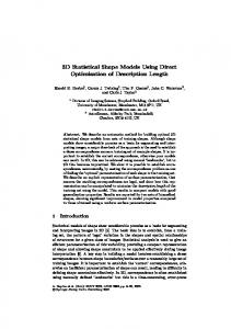
(d) Figure 3: (a) Two views of an object (sheep) scanned as 22,619
unorganized points and reconstructed as a surface mesh using the
�� ) shown method described in [15] by the full medial scaffold ( in (b). Shock � sheets colored by distance � � of formation. (c) Two � ofare views of the curves and vertices. axials are in red and �� ribs are in blue. (d) Two views of the regularized � � ��� verticesandaresmoothed Scaffold. vertices are in green and in pink.
be iterated, removing noise in the process but retaining the “significant corners” which are seen to have a large distance to the transition point [20]. A similar process in 3D requires both a formal understanding of the transitions of the 3D �� which was recently completed [7] and an iterative procedure to regularize the scaffold [14]. Figure 6 identifies the complete list of generic transitions under a one-parameter family of deformations. For example, the � � � -I transition indicates the � introduction of a loop consisting of two curves ���� and � � meeting at a pair of � � � arising from a protrusion on the � surface. Clearly, the sampling process creates perturbations in the observed surface and such sudden changes must be filtered out to the extent possible prior to registration. The approach in [14] identifies such loops and removes them to
1 More details and examples are available from our website: www.lems.brown.edu/vision/researchAreas/Shocks3D/
3
(a)
� ��
(b) Figure 4: From � [7, Fig.1].
perturbations (
both affect the
�
����
The growth of an axis with small
� branches ( �� ) the swapping of topology with slight perturbations.
�� ) and ����
-I
�
��
Figure 5: From [20, Fig.1]; the original square wave is perturbed
��
at numerous places. Traditional smoothing methods smooth away both the noise and corners. Instead, the iterative removal of
� graph smoothes the shape while preserving branches of the its corner (only a subset of the discrete space is shown).
effect both surface smoothing and a regularization of the scaffold, Figure 7. While the approach in [14] used only three of seven transitions, we are now in a position to utilize all seven and have used them for regularization in this paper. Figure 3 illustrates the process of extracting a regularized ��� . The input is assumed to be a set of unorganized points. The process of extracting a scaffold and surface reconstruction are done simultaneously as described in detail in [15] and as shown in Figures 3.(a) and 3.(b). The ��� without the sheets describes the qualitative structure of the shape as shown in Figure 3.(c) but it also contains details pertaining to small as well as large structures. The regularization of the scaffold brings out the essence of the shape as shown in Figure 3.(d). Figure 8 shows another example of a regularized scaffold on the right which features both regularized ridges and regularized generalized axes. It is clear from the scaffold that the significant features like the arms and legs are effectively presented while smoothing the noisy structures. Once a medial scaffold has been regularized, and thus greatly simplified by removing the adverse effects of smaller features and perturbations, we can use it for registration by matching the scaffold structure as described next.
�
� � -II
� � �� -I
3. Matching Medial Scaffolds by the Graduated Assignment Algorithm
� � -II
We extend the graduated assignment [10] algorithm which was used with success for matching 2D shock graphs [17] to matching medial scaffold graphs. Formally, consider two graphs � and � . Refer to nodes of � and � by � � and �� � , respectively, and links of � and � by � �� and �� � ,
Figure 6: Small perturbations in 3D shape cause 7 types of sud � topology. The complete set of generic den changes in the transitions in a one parameter family of deformations is shown in [7]. 4
� � � ��� � � � � � �� � � � � � � � �� ���� ��� � � � � � � ! �� �� � �� (2) represents total similarity between links where � �
� �
�
�
� � � �
� �
�
�
�
� ��
(a)
and � � , and � � represents total similarity between nodes � � and � � . A significant idea in [10] is to extend the discrete assignment problem to a continuous one by embedding it in a large space, where gradient descent can be performed to iteratively move from one assignment to another. A continuous analogy to the discrete assignment matrix (matching matrix) , is , the continuous assignment matrix, which takes values between 0 and 1 with the constraint that has to be a doubly stochastic matrix, i.e., � and � � [18].
� � � � Gradient descent on is used to move from one assignment to another in a Graduated Non-Convexity setting. The Taylor Expansion of the energy function
(b)
�
(c)
�
"�
# "� � �
(d) Figure 7: From [14, Fig.6]. (a) Point samples from a rectangular box, deformed by 5 protrusions (4 on top, 1 on a side). (b) The
� shows five transitions which when removed both smooth the surface (c) as well as regularize the scaffold (d).
"� # "� ���
� "�
� "� � � �"� $ &% ��� � � � � �(' "� % �"� $ (3) � %*).),/ + - "� $ , turns the�� energy minimization into where ' "� , an assignment probmaximizing # �0� � # �� � � ' � is solved lem [10]. This assignment by softassign [18], where an initial matrix is moved toward a solution by increasing a parameter 1 which controls the convexity of the �
�
� �
�
�
� �
�
�
� �
�
�
�
� �
� �
energy landscape (to avoid poor local minima). In each iteration of graduated assignment, the continuous match matrix is best estimated � and normalized such that it gradually moves toward a discretization. This approach was successfully used in matching 2D shock graphs [17]. The node and link attributes were based on the types of shocks and their geometric and dynamic features. A key observation in matching 3D shock graphs is that a quadratic energy function is not sufficiently discriminatory due to the introduction of a third dimension. Thus we employ a order energy term to match the ��� hypergraph.
"�
(a) (b) Figure 8: Laser scanned dataset of a real-life human female body,
� �
24365 ����� ������ � , and � ��� ������� . �� �� � �� �� �� �� � � respectively, where 1 � � �� The match matrix � associates nodes in two graphs: � �� � � 0� � �� � �� � � � � � � � if the node �� corresponds to node �� � � � � � � � � � � � � otherwise. � � �� � � �� � � �� � � 6� � � 7 � � � 7 � � � � � � 7 798 7 7 (1)
provided by Cyberware Inc., comprised of 30,430 points. (a) The surface mesh recovery from the associated “sampling artifact scaf � structure of the interior. fold” [15]. (b) The �
�
� �
�
�
�
�
� �
�
�
� �
�
� ��
� �
(4)
� �
Missing and extra nodes are handled by adding slack � rows and columns. An objective energy function is defined for each possible . Gold and Rangarajan [10] � give a generic definition of for attributed relational graphs (ARGs) as
� �
� �
�
�
�
�
� �
�
�;: �� %=< if3?>A@B3Dand GE FIHKJ0LNC>M LPO
�H @ J BC> M C O < otherwise, � (6) � � � � � ; � � if any links , , , are missing, 8 7 7 � %=< � % � < otherwise, �
�
� �
��
�
�
� �
�� � ��
�
�
� �
��
�
�
�
(a) (7) where is the maximum � radius,
� is the radius at node , � � �� is the link length, is the maximum link length, is the angle between the link � � and � . In Equation (4), and are weights; � � , � � , and � � all take values between 0 and 1, where 1 indicates a perfect match. The link and hyperlink costs can easily be further refined, i.e., by adding radius, curvature, torsion, and other measurements, so that it can also perform local fine registrations. order energy does not (b) Note that the introduction of the affect the computation time very much, due to the sparsity of the order connectivity. After matching, a Euclidean transform is performed to align the two objects together. The best alignment is computed by Singular Value Decomposition (SVD). This completes the proposed global registration algorithm.
�
1
235
�
�
7 8 77
�
�
(c)
2 365
4. Results and Applications The goal of this work is to derive a global alignment for registering unorganized datasets obtained from the same object at different times, using different operators, settings, or equipments. Figure 9 illustrates that two laser range scans each obtained by a different operator, and each containing 20K points, are aligned well by matching their regularized medial scaffolds. Figure 10 shows that two scans at rather different resolutions, roughly 21K and 6K points, are aligned well. We have also verified the accuracy of the results by aligning two distinct random subsamples of a high resolution shape which is itself used as ground truth, Figure 11. We also examined the robustness of the global alignment when large chunks of data were missing. Figure 12a-d shows two scans where in the second scan, the bottom part of the “sheep” was not scanned. Nevertheless the medial scaffold retains sufficient structure to match the two shapes and align them. Similarly, Figure 12e-f shows the successful alignment with another scan where the rear section of the “sheep” is cut off. The global alignment does not require closed surfaces. Figure 13 shows two scans of a pot’s outer surface and the successful alignment of the two surfaces. Since the method is based on graduated assignment matching of regularized medial scaffold, two types of errors can occur. First, the match itself can be erroneous as shown in Figure 14, but given a sufficient number of correct correspondences, the overall registration is not typically affected much. Second, in the process of regularizing the scaffold,
(d) Figure 9: Registering two scans of an object at the same resolution (20K points), obtained by two distinct operators. (a) The sheep object from two scans with different viewpoints. (b) Two views of the shock matching result. (c) Zoom in to illustrate the matches and mismatches. Matched vertices are connected by a thin line. Matched links are colored in pair; unmatched ones are drawn in gray. Although there are mismatches, globally the result is still close to the optimal solution. (d) The final registration result after 20 iterations of ICP with (b) as the initial pose. differences can still remain from one scan to another. Again if a sufficient number of correct correspondences exist, the overall registration is not affected, Figure 15.
5. Conclusions and Future Work We have proposed an automatic global registration method via matching the medial scaffold ( ��� ) using the graduated assignment algorithm. The proposed method is robust to handle missing/extra samples on the data. Results show that it is reliable for practical applications. Future work will aim at refining the medial hypergraph cost function and regularizing all shock transitions to enable fine registration. The proposed method also has a strong potential to handle non-rigid registrations, due to structural 6
(a)
(b)
Figure 10: Left: two scans of an object at different resolutions, top: 21,463 points, bottom: 5,748 points. Right: alignment by matching regularized medial scaffolds.
(c)
(d)
(e)
(a) (b) Figure 11: The ground truth validation on a scanning of Michelangelo’s David head (42350 points, from [13]). (a) 20K and random points from the ground truth, refer to Figure 1 for the other scan of 30K points. (b) The result of ��� matching. The two point clouds are aligned close together. Validation against the ground truth shows that the average square distance is 3.129372 (where the object bounding box ������������ is ). Refer to Figure 1 for the final registration result after 20 iterations of ICP. The final alignment matches the ground truth (final average square distance is 0.000005). and global representation properties of the ��� . Acknowledgments: This material is based upon work supported by the National Science Foundation under Grants 0205477 and 0083231.
(f) Figure 12: The figure illustrates the effect of chunks of missing data. Sheep object with (a) 2,612 sample points, (b) 2,656 sample points in another scan, but the bottom part is completely missing. (c) Alignment as a result of matching the medial scaffold and (d) after a few iterations of ICP. (e) The comparison of scaffolds for another example where the rear portion is cut. Observe that in the
� topology is drastically changed. (f) The missing part, the matching of scaffolds still performs well.
References [1] P. K. Allen et al. New methods for digital modeling of historic sites. CGA, 32–41, Nov/Dec 2003. [2] P. J. Besl and N. D. McKay. A method for registration of 3-D shapes. PAMI, 14(2):239–256, February 1992.
[6] P. J. Giblin and B. B. Kimia. On the local form of symmetry sets, and medial axes, and shocks in 3D. CVPR, 566–573, USA, June 13-15 2000.
[3] H. Blum and R. Nagel. Shape description using weighted symmetric axis features. Patt. Rec., 10(3):167–180, 1978. [4] A. Brennecke and T. Isenberg. 3D shape matching using skeleton graphs. In Proc. Sim. and Vis., 299–310, Mar. 2004.
[7] P. J. Giblin and B. B. Kimia. Transitions of the 3D medial axis under a one-parameter family of deformations. ECCV, 718–724, Denmark, May 28-31 2002.
[5] R. J. Campbell and P. J. Flynn. A survey of free-form object representation and recognition techniques. CVIU, 81(2):166–210, February 2001.
[8] P. J. Giblin and B. B. Kimia. On the intrinsic reconstruction
7
(a)
(b)
Figure 14: Incorrect assignment as a result of erroneous match�
ing of the . Typically this does not affect the overall registration if a sufficient number of nodes are correctly assigned. In this example, incorrect matches (outliers) from the head vertices to the body shift the whole shape in the Euclidean transform. But globally the two shapes are still close enough for ICP to accurately register them. Note that an outlier removal process would improve the result further.
(c)
Figure 15: Effect of transitions: One pot sherd (50,473 points) is matched against its sub-sampled version (10,000 points). Both scaffolds contain relatively few (only 8) vertices, and even worse, some transitions are not fully handled. However, the proposed method gives an alignment that is sufficient close for ICP to obtain the optimal registration.
(d) Figure 13: Ability to match both inside and outside medial struc-
[14] F. Leymarie, P. J. Giblin, and B. B. Kimia. Towards surface regularization via medial axis transitions. ICPR, 2004.
tures. (a) An archaeological pot under two scans. Note that due to range scanner capability, the data has holes. (b) The full scaffold. Note that both the inside and outside scaffold are connected via shock sheets. (c) The proposed method works well on matching the whole scaffold. (d) The registration result after 20 iterations of ICP. The two pot surfaces match perfectly.
[15] F. F. Leymarie. 3D Shape Representation via Shock Flows. PhD thesis, Brown University, May 2003. [16] F. F. Leymarie and B. B. Kimia. Computation of the shock scaffold for unorganized point clouds in 3D. CVPR, vol. 1, 821–827, 2003.
of shape from its symmetries. PAMI, 25(7):895–911, 2003.
[17] D. Sharvit et al. Symmetry-based indexing of image databases. JVCIR, 9(4):366–380, Dec. 1998.
[9] P. J. Giblin and B. B. Kimia. On the local form and transitions of symmetry sets, medial axes, and shocks. IJCV, 54(Issue 1-3):143–157, August 2003.
[18] R. Sinkhorn. A relationship between arbitrary positive matrices and doubly stochastic matrices. Ann. Math. Stat., 35:876–879, 1964.
[10] S. Gold and A. Rangarajan. A graduated assignment algorithm for graph matching. PAMI, 18(4):377–388, 1996.
[19] H. Sundar et al.Skeleton based shape matching and retrieval. SMA, 130–142, Korea, May 2003.
[11] M. Hilaga et al.Topology matching for fully automatic similarity estimation of 3D shapes. SIGGRAPH, 203–212, 2001. ���� [12] IEEE Computer Society. Int. Conf. on 3D Digital Imaging and Modeling, Banff, Canada, Oct. 2003.
[20] H. Tek and B. B. Kimia. Boundary smoothing via symmetry transforms. JMIV, 14(3):211–223, May 2001. [21] J. V. Wyngaerd and L. V. Gool. Automatic crude patch registration. CVIU, 87(1-3):8–26, 2002.
[13] M. Levoy et al.. The digital Michelangelo project: 3D scanning of large statues. SIGGRAPH, 131–144, 2000.
8