Strojarstvo 51 (6) 667-675 (2009)
G. MARUNIĆ et. al., 3D Solid Modelling Inclusion������� ...���� 667
CODEN STJSAO ZX470/1425
ISSN 0562-1887 UDK 744:004.42
3D Solid Modelling Inclusion in Engineering Graphics Course Gordana MARUNIĆ, Vladimir GLAŽAR and Goran GREGOV Tehnički fakultet Sveučilišta u Rijeci (Faculty of Engineering University of Rijeka), Vukovarska 58, HR - 51000 Rijeka, Republic of Croatia
[email protected]
Subject review The increasing use of solid modelling has had considerable impact on changes in the design process, which has resulted in a stronger relation between design and engineering graphics. These attempts can be followed shifting from modest changes, by inserting 2D and 3D CAD models into introductory engineering graphics course to the approach of implementing parametric, feature-based and constraint-based modelling, which have led towards the development of 3D model centred engineering curriculum. This paper presents some characteristic approaches chosen from numerous contributions dealing with the introduction of new topics and technology in engineering graphics education, as well as the example of 3D modelcentred engineering curriculum. A review of topics that are the most common proposal for an introductory engineering graphics course are extracted, regardless of different approaches that should accomplish the link between 3D modelling, engineering design and applications. A short description of engineering graphics courses and the topics covered at the University of Rijeka, Faculty of Engineering, as a result of revision that has emphasized 3D modelling and its role in the concurrent engineering design process is also presented.
Uključivanje 3D modeliranja tijela u kolegij inženjerske grafike
Keywords Engineering Graphics Engineering Design Process 3D Modelling Ključne riječi Inženjerska grafika Proces inženjerskog konstruiranja 3D modeliranje
Received (primljeno): 2008-12-15 Accepted (prihvaćeno): 2009-10-30
Pregledni članak Na promjene u procesu konstruiranja znatno je utjecala povećana uporaba modeliranja tijela, što je rezultiralo snažnijim odnosom između konstruiranja i inženjerske grafike. Mogu se pratiti nastojanja, od stidljivih promjena uključivanjem 2D i 3D modela u uvodni kolegij inženjerske grafike, do pristupa upotpunjavanja parametarskim modeliranjem na osnovi značajke i ograničenja, što dovodi do razvitka inženjerskog nastavnog programa s 3D modelom u središtu. Ovaj rad predstavlja neke karakteristične pristupe izabrane iz brojnih doprinosa koji obrađuju uvođenje novih tema i tehnologija u obrazovanje inženjerske grafike, kao i primjer inženjerskog nastavnog programa s 3D modelom u središtu. Izdvojen je pregled tema koje su najčešći prijedlog za uvodni kolegij inženjerske grafike, bez obzira na različite pristupe koji trebaju ostvariti vezu između 3D modeliranja, inženjerskog konstruiranja i aplikacija. Također je predstavljen kratki opis kolegija inženjerske grafike i obuhvaćenih tema na Tehničkom fakultetu u Rijeci, kao rezultat dorada koje daju naglasak na 3D modeliranje i njegovu ulogu u procesu istodobnog inženjerskog konstruiranja.
1. Introduction Over the past ten years, engineering graphics has changed immensely, as interest has transferred from 2D drafting skills to 3D solid modelling. Traditionally, an engineering graphic course has been developed around ortographic projections, and when the conditions have been fulfilled, the tool has changed, but the same 2D (CAD) model-drawings have been produced.
Challenges have arisen from the development of 3D solid modelling software (e.g. CATIA, Mechanical Desktop, Pro/Engineer, Solidworks), as well as from industry demand for engineers who are familiar with such technology. The instruction of engineering graphics has had to respond to these challenges, taking into account the changed environment by building an educational development that consequently reflects all areas where graphics are implemented.
668
G. MARUNIĆ et. al., 3D Solid Modelling Inclusion...
At the end of the past century, the most important recommended topics were 3D visualization skills, parametric modelling, 3D solid modelling, and manual sketching [1]. The necessity of new teaching method investigations to ensure the effectiveness of graphics education [2] was underlined. For more than twenty years, 3D modelling has developed from a wireframe to solid model, and more recently to feature-based and constraint-based models that are convenient for many engineering applications. The adoption of a 3D solid modelling approach assumes that the models are not treated as a geometrical representation, but as the centre of design process database [3-6].
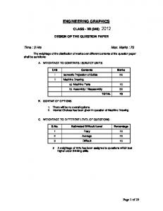
Figure 1. Instructional sets [15] Slika 1. Obrazovni setovi [15]
Strojarstvo 51 (6) 667-675 (2009)
In most cases, traditional methods assume one correct representation for a given part, but in solid modelling a part can be created by several approaches, some being superior to others. Due to the relationship between the part modelling approach and the design intent, this technology provides an excellent opportunity for introducing design [7, 8]. Much effort has been done over recent years to adjust engineering graphics courses and curricula at initial stages of engineering education. It is of great importance to provide the students with accurate information about engineering careers: to give students an appreciation of what an engineer does and how he does, and to emphasize
Strojarstvo 51 (6) 667-675 (2009)
G. MARUNIĆ et. al., 3D Solid Modelling Inclusion������� ...���� 669
design as a fundamental aspect of engineering [9-11]. The adjustments in engineering graphics education have been conducted by some essential questions [12]. How much time should be spent for the contents connected to the documentation in curriculum? The related knowledge and skills are contained in traditional engineering graphics – multiview drawings, standards for dimensioning and tolerancing, sectional views, auxiliary views. Are these “drawing” practices desirable for potential employers, and do they want students to manage with modelling, animation, simulation and data representation? The answers have resulted in a variety of implemented changes, related to the adopted approaches and consequent learning/teaching techniques depending on an added emphasis to certain traditional topics and the introduction of new ones [13-15]. Through the following chapters, various approaches to the adjustment and development of engineering graphics courses/curricula are presented guided by the idea of 3D modelling introduction i.e. by respecting the role of graphics in engineering design process. The examples are presented by choosing characteristic ones from early attempts up to the present.
2. Implementing 3D modelling and visualization in engineering curriculum The proposed evaluation of curriculum changes in engineering graphics that follows is separated as it represents a formal research base tested before being implemented in widespread instructional use [15]. The problem of effectiveness determination of various engineering graphics educational aids in developing students spatial abilities was addressed in a research project that resulted in engineering graphics course for first year engineering students. By introducing new technology and new techniques of computer graphics, students learnt not just the fundamentals of engineering graphics but CAD principles also. After a traditional engineering graphics set, over the next two years courses with combined instructional sets took place. The instructional sets shown in Figure 1 were combined as follows: Computer Aided Drafting (CAD) + Traditional Engineering Graphics Computer Aided Visualization (CAV) + Sketching Visualization CAV + Traditional Engineering Graphics
The study showed a significant improvement of spatial abilities for all courses, but depending on the used instructional set. There was no difference among end test scores, or the scores were higher during the years where the computer based course was introduced. The second result shows that developed instructional sets combined in the first and second semester courses all enhance equally well visual abilities. The authors further emphasized that instructional programs must include basic spatial problems to help haptic individuals to develop the necessary visualization skills; at the same time, it should offer more advanced and complex spatial problems dedicated to “good” visualisers. The changes in a learning environment of a computer based instructional set have to be adjusted for all individuals with different learning approaches. Although created approximately at the same time as the presented study, in the last decade of the past century, the example of how 3D modelling and visualization should be incorporated into a first year engineering curriculum [9] is a much more radical approach than the previous one. After two years, when traditional engineering graphics course were eliminated and material integrated into other courses, geometrical modelling, computer aided design and the basic ideas of visualization were introduced for students during their first semester. The authors explained their standpoint by the fact that we deal with real 3D objects and students learn about the geometry of real world objects by manipulating them; they learn about 3D computer models in the same way. As students work with a CAD system they learn how objects map into views. In relation to an essential skill for any engineer, how to create and read drawings (symbols and conventions used in engineering drawings), a general course can introduce common conventions and notations, while many details of documentation must be left to certain engineering disciplines. The students learn to capture their ideas as 3D models, and gain an early understanding of the role of design in engineering. In their first CAD lesson, they learn to construct a solid model and view it from multiple perspectives and to render it. The topics covered are Boolean operations, working in multiple spaces, a variety of solids modelling techniques, annotating the model and making it. In the paper cited, the topics of traditional engineering graphics that were integrated in to other courses have not been specified, this does not provide the generation complete insight into the proposed approach, but it is worth mentioning.
670
G. MARUNIĆ et. al., 3D Solid Modelling Inclusion...
3. Incorporating design contents into the first year of engineering course/ curriculum The importance of visualization skills and visual communication for design process has resulted in the trend of introducing engineering students to the basic concepts of design in an introductory engineering graphic course combined with the emphasis on design throughout the curriculum. The course was developed to enable first year engineering students to become familiar with the engineering design process along with the acquisition of free-hand sketching and 3D solid modelling skills [16]. The centrepiece of the course is the group design project that allows students to combine knowledge gained in both graphics and design. The approach similar to the previously-described one, is presented in [17] for a new introductory graphics course implementing the use of art-based freehand drawing techniques, a nonparametric 3D solid modelling, basic rules of technical drawing and the design process. The most important goals that are common to revision and redesign of the introductory engineering course/curriculum undertaken relating to the design aspects implementation are improvement of student visualization skills through 3D solid modelling, student sketching skills, focusing also at the same time on traditional engineering graphics material. To accomplish these, emphasis has been placed on the use of individual [17-18] and group [16-19] design projects, which enable students to a embrace broader picture of drawing and 3D modelling in the design process. The implementation of new introductory courses of engineering graphics has been supported by a variety of educational technologies followed by application of modern pedagogical approaches. The results of a departure from the traditional syllabus have been declared as very positive; the students show improved visualization and sketching skills and they are capable of accomplishing rather complex solid modelling design.
4. Using parametric, feature-based and constrained, solid modelling in engineering graphic course A new methodology for teaching engineering graphics with emphasis on parametric, feature-based solid modelling was presented in [7]. Through use of this methodology that provides integration of design and engineering graphics, the student can identify alternative approaches for creating the model, evaluate their ability
Strojarstvo 51 (6) 667-675 (2009)
to capture real design intent accurately, and incorporate the design intent by defining an appropriate set of datum planes and following good dimensioning practices. The difference between traditional 2D graphics systems and parametric, feature-based systems are presented in Table 1. The topics that the introductory course of engineering graphics should cover were guided by US national trends in engineering graphics in both industry and education [12]. The proposed course was based on the idea that 3D model is the centre of design process. These topics are: visualization, sketching, solid modelling, constrainedbased modelling geometry, dimensioning, multiview and pictorials, manufacturing processes, working drawings, sectional views, auxiliary views and assemblies. Among these topics, two reflect the difference between the traditional and new approach to engineering graphics course; the reason for their inclusion was explained as follows. It was reported for 28 companies under consideration, that constrained-based, parametric modelling is more frequently used compared with static solid or surface modelling software. For the creation of new design, constraint-based modelars have been used 68 %, related to only 15 % of static solid modelling tools. The purpose of including manufacturing processes in the introductory course was to provide students with an understanding of the main methods for creating parts. Along with understanding of dimensional constraints, students can model parts that reflect potential design changes. Some topics assumed new meaning, arising from an actual approach. So the dimensioning and geometrical relations represent tools for connection of design intent with 3D model. The documentation represents a byproduct of the 3D modelling process with 3D model as a dynamic entity.
5. Integration of engineering graphics learning more thoroughly with the other courses A revision of engineering graphics curriculum was undertaken [20] guided by the achievement of students’ certain core competencies. It is important that students are able to: - effectively communicate engineering design information (through engineering sketches, 2D CAD drawings, layouts, schematics, etc., 3D solid models, CAM programs and Computer Aided Analysis Programs), - produce engineering communication that is according to adequate standards,
Strojarstvo 51 (6) 667-675 (2009)
G. MARUNIĆ et. al., 3D Solid Modelling Inclusion������� ...���� 671
Table 1. Differences between traditional 2D graphics systems and 3D parametric, feature-based graphics systems [7] Tablica 1. Razlike između tradicionalnih 2D grafičkih sustava i 3D parametarskih, grafičkih sustava na osnovi značajke [7]
- utilize the above methods and programs efficiently in design (understand the proper role of fits and tolerances in graphical design), - have a fundamental up-to-date working knowledge of CAM,
- have a general and fundamental working knowledge of FEM Analysis, Simulation, and Computational Fluid Dynamics. The author’s standpoint was that the list of expected competences of the proposed curriculum can be
672
G. MARUNIĆ et. al., 3D Solid Modelling Inclusion...
successfully achieved by considering together various methods that include: choice of graphic tools (programs) and methods, increase and progressive exposure to graphical communications and methods (to provide for integration with other courses in the curriculum), improved teaching methods, assessment in each course by integration with other courses.
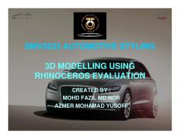
6. 3D model centred curriculum In [5] the curriculum was examined, where each course stresses a concurrent engineering design process with 3D modelling at the centre according to concurrent engineering design model [21], as presented in Figure 2. The reason for the introduction of the courses contained in this curriculum was explained for each course. The topics in the course Introduction to Solid Modelling included visualization, sketching, solid
Strojarstvo 51 (6) 667-675 (2009)
modelling, constraint-based modelling, geometry, dimensioning, multiviews and pictorials, manufacturing processes, working drawings, sectional views, auxiliary views, and assemblies of solid models. The focus of the course is on a model creation, extracting information from the solid model, and on the decision-making process related to creating constraint-based geometry and the development of modelling strategies that respect design intent. The course Surface Modelling builds on the knowledge from the previous course. The creation of simple and complex surface geometry from all types of forms, parametric surface modelling techniques similar to those used in mechanical design environment (complex fillets and rounds, parting lines for moulded or cast parts, complex geometry for thin-walled objects) are included. In order to enable understanding of assemblies, the course Component Interaction should cover the following topics: basic assembly construction, top-down construction, assembly skeletons, assembly layouts,
Figure 2. Concurrent engineering design process with 3D modelling at the centre [5] Slika 2. Proces istodobnog inženjerskog konstruiranja s 3D modeliranjem u središtu [5]
Strojarstvo 51 (6) 667-675 (2009)
G. MARUNIĆ et. al., 3D Solid Modelling Inclusion������� ...���� 673
parameters, constraints/mates, and tolerancing issues. The assumption is adopted for the treatment of assembly components at an operating-system level and direct influence of the associative characteristics of a constraintbased modelling tool on the geometry modification process. As the constraint-based modelar is used, students should adopt the way the documentation can be added to the 3D model and develop traditional documentation from 3D model; the course Engineering Documentation deals with. To accomplish these, students have to learn at least about the standards and practices for representing objects (multiview drawings and sectional views), standards for dimensioning and tolerancing, auxiliary views, threads and fasteners-by using part libraries and drawing templates. According to this approach, one of the course objectives will be the interpretation of 2D documentation rather than explicit production of drawings. Constraint-based modelars have continuously integrated new analysis possibilities and more options for exporting data to other applications for analysis. Through the course Graphical Analysis the students will be able to make some recommendation to a trained analyst, based upon the analysis of design geometry in relation to more obvious errors. The real potential of 3D modelling centred design process is utilising the model not only for design documentation, but in downstream applications, too. The activities of the course Downstream Applications through use of 3D model are basic web creation, information publishing from the design process creation of coloured images for various purposes. The students will also be introduced to prototyping applications and the generation of machining data for other stages of engineering data process. Students who deal with different file types, translation utilities, different database structures and used modelling kernels, are welcomed, as all CAD software packages are supplied by all components needed for design and production, and the design data are moved between various software packages. Students have to be able to evaluate model geometry conducted by proved modelling techniques and that is the course Data Integration activities support. Through the course Data Management, students will adopt an understanding of client /server environment and its implications on the privileges of the users. They will learn about different vaulting and security procedures involved with maintaining and sharing engineering data. The course will be focused on basic hardware and software installation, configuration and management of databases, and a thorough understanding of engineering lifecycle.
7. Engineering graphics at University of Rijeka Faculty of Engineering The courses that embrace engineering graphics are taught at Department of Mechanical Engineering Design, Chair of Engineering Graphics. These courses, taking into consideration bachelor’s degree studies (university), are of different structure, depending on whether they are developed for the studies of mechanical engineering and naval architecture, or for electrical engineering study. As the courses for mechanical engineering and naval architecture studies have more complex structure, these courses will be presented. The declination from traditional engineering graphics courses began in 1995, when new course named Technical Drawing started. This course contained residuals of descriptive geometry and all topics needed for the development of an engineering drawing according to actual standards. The tool for the generation of 2D CAD models was added to the traditional manual tool, and the use of computer with software package AutoCAD was introduced. Although 3D CAD modelling was not performed practically, the course contained topics that enabled proper insight into the role of graphics in traditional and concurrent engineering design, and basic ideas of 3D modelling techniques. The beginning of the Bologna process was an adequate opportunity for more significant change of engineering graphics courses and introduction of exercises that emphasise the importance of graphics in design and communication. Due to certain circumstances, the conditions for earlier changes were not fulfilled, and this was especially true for the needed hardware and software support as well as adequately equipped classrooms. Two courses were established in the curriculum for the year 2005: Engineering Graphics in the first semester, and Modelling by Computer in second one. In the course Engineering Graphics the following topics are positioned: multiview and pictorial sketching and drawing, dimensioning and tolerancing, surface texture, sectional views, auxiliary views, working drawings, assemblies. The use of traditional tool is minimal and focus is on the generation of 2D and 2D CAD models by freehand sketching and by use of AutoCAD, respectively. Although these topics can look just like traditional ones, the course begins with presentation of the role that engineering graphics has in the process of traditional and concurrent engineering design, which is explained in general. Furthermore, the explanation of certain topics through the course is always related to the potential application for 3D modelling.
674
G. MARUNIĆ et. al., 3D Solid Modelling Inclusion...
The reasons for the introduction of a new course Modelling by Computer into engineering graphics curriculum were to emphasize in a stronger and clearer manner the role of engineering graphics in the design process, to the consider central position of 3D model in design database and, consequently, the possibilities for utilizing this model data for the entire design process activities. Along with these goals, students will adopt new tools for graphics communications that can considerably increase their capabilities in visual reasoning and problem solving. The students’ exercises and projects are accomplished by use of software package CATIA. The course Modelling by Computer embraces the following topics: design process, CAD system, 3D modelling in design process, geometry for modelling, viewing a model, types of 2 and 3D models, solid models, parametric, feature-based modelling, application of model database (basics), documentation graphics. Furthermore, in the first semester of they master’s degree (university) of mechanical engineering study, the module Design and Mechatronics, the new course Engineering Visualization (an introduction to Scientific Visualization), was implemented in 2008. This course will prepare students to transform the symbolic into geometric, to observe simulations and computations, and to acquire techniques that are broadly applicable. Visualization offers a method for seeing the unseen [22], the phenomenon beyond the data, everywhere data is collected and needs to be examined. The students develop their projects by use of free specialised software package Open DX. The topics covered by this course are: definition, goals, application and history of visualization, perception of visual, data in visualization, and visualization techniques.
8. Conclusions It is obvious that the engineering graphics courses and curricula have been subjected to intensive changes that have taken the place through the past twenty years. The approaches have been adopted that included topics as well as ways of teaching and learning, considering that traditional engineering courses have no longer corresponded and have not satisfied the requirements of the actual environment, resulting from technological development and industrial needs. These needs and attempts to fulfil them can be followed primarily through progressive inclusion of methodologies and topics intended to reflect change in the design process due to solid modelling and, consequently, the role of graphics in design process.
Strojarstvo 51 (6) 667-675 (2009)
The focus has shifted from 2D and even 3D CAD techniques, towards the development of general skills that enable students to consider and interpret solid modelling and drawing as essential parts of design process, by spreading the role of engineering graphics much more beyond the documenting and communication. Nevertheless the proposed approaches have been different in relation to the range and dynamics of the changes, the section of topics that have to be covered and supported today by adequate learning /teaching, can be extracted as essential for introductionary engineering graphics course that respect the 3D model as a centre of design process. These topics are: visualization, sketching, solid modelling, parametric, feature-based modelling and constraint-based modelling, dimensioning, multiviews and pictorials, manufacturing processes, working drawings, sectional views, auxiliary views, assemblies. The opinion expressed in [23] over ten years previously, is still actual: “The role of graphics in engineering design will become more, not less, important as we attempt to harness the potential of the information revolution.”
REFERENCES [1] BARR, R.E.: Planning the EDG Curriculum for the 21st century: A proposed team effort, Engineering Design Graphics Journal, 63, 2 (1999), 4-12. [2] AULT, H. K.: 3-D geometric modelling for the 21st century, Engineering Design Graphics Journal, 63, 2 (1999), 3342. [3] BARR, R.E.; JURCIC, D.; KRUEGER, T.J.; WALL, L.S.; WOOD, B.H.: The Freshman Engineering Design Graphics Course at the University of Texas at Austin, Journal for Geometry and Graphics, 2, 2 (1998), 169179. [4] LOCHART, S. D.; JOHNSON, C.M.: Engineering Design Communication, Conveying Design Through Graphics, Prentice Hall, 2000. [5] BRANOFF, T. J.; HARTMAN, N. W.: The 3D Model Centered Curriculum: How Do We Prepare Our Students?, ASEE Southeast Section Conference, 2002. [6] BERTOLINE, G. R.; WIEBE, E. N.; MILLER, C. L.; NASMAN, L. O.: Fundamentals of Graphics Communication, Mc Graw Hill, 2005. [7] CONDOOR, S. S.: Integrating Design in Engineering Graphics Courses Using Feature-based, Parametric Solid Modeling, 29th ASEE/IEEE Frontiers in Education Conference, San Juan Puerto Rico, (1999), 13-17. [8] HOFFMANN, C.M.: Constraint-Based CAD, JCISE 5, 3 (2005), 182-187. [9] RICHARDS, L. G.: Incorporating 3D Modeling and Visualization in the First Year Engineering Curriculum, http://fie.engrng.pitt.edu/fie95/3c5/3c55/3c55.htm, 1995.
Strojarstvo 51 (6) 667-675 (2009)
G. MARUNIĆ et. al., 3D Solid Modelling Inclusion������� ...���� 675
[10] CASTRO-CEDENO, M.H.: The Role of Engineers in the Creation of Engineering Drawings-Past, Present, Future, 59th Midyear Annual Meeting of the Engineering Graphics Division of the American Society of Engineering Educators, Williamsburg, 2004.
[17] NEWCOMER, J.L.; RAUDEBAUGH, R.A.; McKELL, E.K.; KELLEY, D.S.: Visualization, Freehand Drawing, Solid Modelling, and Design in Introductory Engineering Graphics, 29th ASEE/IEEE Frontiers in Education Conference 12d2-1-12d2-6, San Juan, 1999,
[11] LAMANCUSA, J.S.; JORGENSEN, J.E.; ZAYASCASTRO, J.L.; RATNER, J.: The Learning Factory - A new approach to integrating design and manufacturing into engineering curricula, ASEE Conference Proceedings, Anaheim, 2262-2269, 1995.
[18] NASTASI, J.; SHEPARD, K.; CHASSAPIS, C.: Revision of Freshman Engineering Graphics to Support An Evolving Core Design Sequence, American Society for Engineering Education, 2006.
[12] BRANOFF, T.J.; HARTMAN, N. W.; WIEBE, E. N.: Constraint-Based, Three-Dimensional Solid Modelling in an Introductory Engineering Graphics Course: Reexamining the Curriculum, Engineering Design Graphics Journal, 66, 1 (2002), 5-10. [13] BARR, R.E.; KRUEGER, T.J.; AANASTOOS, T.A.: New Digital Engineering Design Process, Engineering Design Graphics Journal, 66, 3 (2002), 6-11. [14] HOWELL, S.K.: The Use of a Parametric Feature Based CAD System to Teach Introductory Engineering Graphics, Engineering Design Graphics Journal, 59, 1 (1995), 2733. [15] GRADINSCAK, Z.; LEWIS, W. P.: An evaluation of curriculum changes in engineering graphics, IDATER 95 Loughborough University of Technology, (1995), 80-87. [16] NOKLEBY, S.B.; POP-ILIEV, R.: A Design Challenge – Incorporating Design into the First Year Engineering Curriculum, 2nd CDEN International Conference on Design Education, Innovation, and Practice, Kananaskis, 2005.
[19] LEAKE, J.M.: Redesign of a Course in Engineering Design Graphics, ASEE Annual Conference, St. Louis, 2001. [20] FISHER, K.; COOK, K.: Improving Learning of Engineering Graphics through a Combination of Techniques, American Society for Engineering Education, AC 2007-238, 2007. [21] BARR, R. E.; JURICIC, D.; KRUEGER, T. J.: The Role of Graphics and Modelling in the Concurrent Engineering Environment, Engineering Design Graphics Journal, 58, 3 (1994), 12-21. [22] ACM SIGGRAPH: Visualization in Scientific Computing, 1987. [23] JENISON, R. D.: New Directions for Introductory Graphics in Engineering Education, Journal for Geometry and Graphics, 1, 1 (1997), 67–73.