2014 IEEE International Conference on Robotics & Automation (ICRA) Hong Kong Convention and Exhibition Center May 31 - June 7, 2014. Hong Kong, China
3D SPIHT for Multi-lead ECG Compression Sani M. Isa, Wisnu Jatmiko, Aniati Murni Arymurthy The Set Partitioning in Hierarchical Trees (SPIHT) is a generalization of Embedded Zerotrees Wavelet transform (EZW) proposed by Said and Pearlman [1]. SPIHT uses partitioning trees to keep significant and insignificant wavelet coefficients. The partitioning step provides very efficient significance map encoding such that arithmetic coding of this map provides very little gain. SPIHT algorithm sends the binary representation the integer value of the wavelet coefficients. Significance map encoding is followed by refinement step, which refines the representation of the significant coefficients.
Abstract— In this paper we proposed the implementation of 3D Set Partitioning In Hierarchical Trees (SPIHT) algorithm to a multi-lead ECG signal compression. The implementation of 3D SPIHT decorrelates three types of redundancy that commonly found on a multi-lead electrocardiogram (ECG) signal i.e. intra-beat, inter-beat, and inter-lead redundancies. To optimize overall compression performance we also proposed beat reordering and residual calculation technique. Beat reordering rearranges beat order in 2D ECG array based on the similarity between adjacent beats. This rearrangement reduces variances between adjacent beats so that the 2D ECG array contains less high frequency component. Residual calculation optimizes required storage usage further by minimizing amplitude variance of 2D ECG array. The experiments on selected records from St Petersburg INCART 12-lead Arrhythmia Database show that proposed method gives relatively low distortion at compression rate 8 and 16.
Several ECG signal compression methods based on SPIHT and its modification has been presented recently, Lu et al. who proposed 1D SPIHT coding for single ECG signal compression [3]. Pooyan et al. divided single lead ECG signal into non-overlapped frames and applied 1D SPIHT coding on each frame of ECG signal [4]. Goudarzi et al. proposed SPIHT coding on multiwavelet transformed 2D ECG array of single lead ECG signal [5]. Rezazadeh et al. applied similar technique to Goudarzi to construct 2D ECG array with the implementation of sub-band energy compression before SPIHT coding [6]. Tai et al. also used similar technique to construct 2D ECG array of single lead ECG Signal and proposed modified SPIHT coding that divided wavelet transformed image into three partitions [7]. Sharifahmadian presented enhanced SPIHT coding that limits redundant evaluation in the sorting pass of SPIHT for single and two leads ECG signal compression [2]. Shahraeian and Fatemizadeh applied vector quantization on residual image obtained from SPIHT coding [8]. Nayebi et al. proposed run length coding on SPIHT. Nayebi used similar 2D ECG array to Goudarzi, as an input for SPIHT coding [9]. Wang et al. applied lifting wavelet transform and adopted different threshold value for high frequency subband in SPIHT coding [10]. Sharifahmadian [2] used the enhanced SPIHT coding that limits redundant evaluation in the sorting pass of SPIHT. Among all described methods, only Sharifahmadian who proposed SPIHT-based compression method for multi-lead ECG signal.
I. INTRODUCTION Electrocardiogram is a test for the electrical activity of the cardiac muscles of the heart. The pattern in the ECG signal identifies specific order of electrical activities on every heartbeat; therefore ECG is very important for cardiac monitoring. Some of cardiac disorders can be visually identified from the pattern on the ECG signal, particularly on improper electric conduction of damaged cardiac muscles. A qualified professional can determine the location of the damaged cardiac region from the abnormal patterns in ECG signal. Each lead of ECG signal is acquired from an electrode at specific location on the body. Since every ECG lead gives specific point of view of the heart, different ECG leads are required to cover different areas of the heart. Current standard of ECG equipment consists of 12-leads configuration. 24 hours recording of 12-leads ECG with 256 Hz sampling rate, 11bit/sample data resolution requires about 396 Mbytes of storage. Recent advances in sensor technology allow ECG recorded at higher sampling rate and data resolution. As the sampling rate, data resolution, and observation time increase, the amount of storage requirement also increases. The amount of transmission time and bandwidth also increase when the ECG signal needs to be transmitted. Therefore, ECG signal compression becomes an important issue in biomedical engineering and signal processing research area.
In this paper we proposed a wavelet-based 12 leads ECG signal compression method using 3D SPIHT optimized with beat reordering and residual calculation. Unlike the previous SPIHT based methods that mostly worked on single or two leads ECG signal, we compressed 8 leads from multi-lead ECG signal. 3D SPIHT used to reduce the intra-beat, interbeat, and inter-lead redundancies on multi-lead ECG signal. To apply this coding algorithm, a multi-lead ECG signal needs to be represented as three-dimensional data. First, each lead of multi-lead ECG signal is converted into ‘ECG image’ or 2D ECG array. Each 2D ECG array then stacked into to 3D ECG array that represents three-
Sani M. Isa is PhD student of Faculty of Computer Science, University of Indonesia, Kampus UI, Depok 16424, West Java, Indonesia (phone: +6221-7863419 fax: +6221- 7863415 e-mail:
[email protected]) Wisnu Jatmiko is Lecturer of Faculty of Computer Science, University of Indonesia, Kampus UI, Depok 16424, West Java, Indonesia (e-mail:
[email protected]) Aniati Murni Arymurthy is Professor in Faculty of Computer Science, University of Indonesia, Kampus UI, Depok 16424, West Java, Indonesia
978-1-4799-3685-4/14/$31.00 ©2014 IEEE
488
dimensional version of multi-lead ECG signal. Beat reordering applied to reduce the variance among adjacent beats by rearranging the order of each beat cycle in 2D ECG array based on their similarities. The arrangement will improve overall compression efficiency since wavelet based method works very efficient on signal with minimum variance [11]. Residual calculation optimizes required storage usage further by minimizing amplitude variance of 2D ECG array. This paper is organized as follows: beat detection and normalization, 2D ECG array construction, beat reordering, residual calculation, short introduction to the SPIHT coding, and 3D SPIHT are presented in section II. The evaluation of the proposed method using the selected records from St Petersburg INCART 12-lead Arrhythmia Database are explained in section III. Finally, the conclusion will be given in section IV.
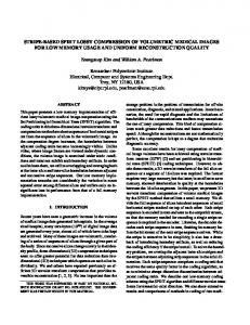
Figure 1. Schematic diagram of the proposed method
be restored to the original duration, we saved this information for ECG signal reconstruction purpose. B. 2D ECG Array Construction An optimal ECG signal compression needs to decorrelate both intra-beat and inter-beat correlations to achieve high compression rate at low distortion. Those correlations can be obtained by arranging several heartbeat cycles (128 in this study) into two-dimensional form or 2D ECG array. The intra-beat correlation can be seen on each column, while the inter-beat correlation can be shown on each row of 2D ECG array. Instead of choosing one cardiac cycle of ECG signal (P-Q-R-S-T), we use two adjacent R wave peaks as the beginning and end of each cycle. Each cycle consists of second half of R wave signal, S, T, P, Q, and first half of next R wave signal. 128 ECG cycles arranged into 2D ECG array so that each row of the array represents one ECG cycle. Fig. 2 shows 2D and 3D view of 2D ECG array. Since the input signal could be longer than 128 heartbeats, there will be more than one 2D ECG array on each lead of multi-lead ECG signal.
II. METHODOLOGY Fig 1. shows the schematic diagram of the proposed method. The first step through the fifth step of the compression stage applied independently to each lead of multi-lead ECG signal. First, QRS complexes from each heartbeat are detected. The duration of each beat cycle then calculated from the RR interval of detected QRS complexes. Next, we apply the modification of period and amplitude normalization (PAN) method to normalize each heartbeat duration [12]. After all heartbeat durations are equal, several heartbeat cycles reorganized into 2D array form. To reduce the variation among adjacent beats, we apply beat reordering step. Residual calculation will optimizes required storage further by minimizing amplitude variance of 2D ECG array. 2D Wavelet transform then applied to the output of residual calculation. This transformation step will decorrelate the residual data. The result of transformation from each step then arranged as 3D data structure. The final step is 3D SPIHT coding which employs wavelet coefficients from previous step as an input. Detail explanation of each step will be covered in the next part of this paper.
C. Beat Reordering The ECG signal has pseudo-periodic characteristic, but there are also probability that the certain heartbeats has very different shape than others. Beat reordering will increase the regularity and predictability of the signal by rearranging the order of each cycle in 2D ECG array based on their similarities. In this research, beat reordering implemented in two phases:
A. Beat Detection and Normalization The first step of the compression stage is beat detection. In this study we applied the QRS detection algorithm from Pan and Tompkins [13]. There are six stages in this algorithm i.e. band pass filter, high pass filter, derivative, squaring, integration and search procedure. Band pass filter reduces the noises caused by power line interference, baseline wander, and T-wave interference. The slope information of each beat cycle candidate then computed using derivative calculation. The squaring stage converts signal amplitudes into positive value. To obtain shape information of each beat cycle candidate, the output from previous stage is used as an input to moving integration process. The last stage of this algorithm is searching for QRS complex locations using adaptive threshold approach.
1.
Cluster each row of 2D ECG array using Fuzzy CMeans Clustering.
2.
Reorder row position on each cluster based on their distance to the centroid. The distance measure used in this research is Euclidean distance.
Similar heartbeat cycles will be grouped on the clustering step so that each cluster contains similar heartbeats only. Since reordering step rearranges the location of each heartbeat based on their similarities, the variation among adjacent beat cycles will be minimum. As a result, the rearrangement adds a regularity and predictability to the 2D ECG array. The position of each cluster on the 2D ECG array does not affect beat reordering efficiency since the frequency distribution of the array is only affected by the order of heartbeats inside each cluster. Therefore, it is not necessary to sort the position of each cluster on the 2D ECG array. The
To construct 2D ECG array, all heartbeat duration need to be normalized into a constant value. For this purpose, we used the modification of PAN method to normalize each heartbeat duration without amplitude normalization step since this step does not give a substantial contribution to optimize overall compression stage. Since all heartbeat duration should 489
Figure 2. 3D (left) and 2D (right) view of 2D ECG matrix
Figure 4. The illustration of residual calculation step
Fig. 4 shows the illustration of residual calculation step. First, C1, C2, …, Cn which denotes the centroid vector of cluster 1, 2, …, n decomposed (up to 4 levels) using discrete wavelet transform (DWT) into W1, W2, …, Wn. Inverse discrete wavelet transform (IDWT) then applied to the 20 most significant coefficients. Inverse transform reconstructs each centroid vector as M1, M2, …, Mn. Residual 2D array obtained from the subtraction of each beat cycle on each cluster from their reconstructed centroid vector i.e. M1, M2, …, Mn. Reversed step of residual calculation applied to the decompression stage i.e. substitute the subtraction with the addition. The process of residual calculation is lossless since there is no information loss during the process.
Figure 3. 3D (left) and 2D (right) view of 2D ECG matrix after beat reordering applied
position of each heartbeat cycle will be restored in the decoding stage, so that this information should be saved. Fig. 3 shows a 2D ECG matrix after beat reordering applied. Light colored pixels on 2D view denote the samples with high amplitude such as the peak of P, R, and T wave, while dark colored pixels denote the samples with low amplitude such as Q and S wave. As can be seen on the figure, beat-reordered 2D ECG array is smoother than those on Fig. 2. 2D view of 2D ECG matrix on Fig. 3 shows that the positions of the peaks are already grouped. Beat reordering step reduces the variances among the adjacent heartbeats. Wavelet-based data compression method such as SPIHT works very efficient on low variance data [11].
E. SPIHT Overview Set partitioning in hierarchical trees is one of the “state of the art” wavelet-based coding techniques, which orders the transformed coefficients using a set-partitioning algorithm based on the sub-band pyramid. The information required to reconstruct signal is very compact since SPIHT sends only the most important ordered coefficients information in each iteration. SPIHT is also one of the codecs that provides userselectable bitrate and progressive transmission of encoded bit stream. Encoding process can be terminated at any point, allowing a bitrate or distortion parameter to be met exactly. Embedded coding is comparable to binary finite precision representation of a real number. A string of binary digits can represent any real number. For each digit added to the right of binary digits, the precision of the real number becomes higher. Encoding can stop at any time and provide the best representation of the real number achievable within the framework of the binary digit representation. SPIHT encoder also can be terminated at any time and provide the best representation of the signal achievable within the framework [1].
D. Residual Calculation The main objective of residual calculation is to reduce the amplitude variation of the ordered 2D ECG array. The centroid of a cluster is the average point in multi-dimensional defined by the data dimension. The differences between each data inside a cluster and their centroids will be smaller than the original data. In residual calculation step, each row of 2D ECG array subtracted from its centroid. Since we need the centroid to reconstruct the original data, we should keep the centroid information in memory for the decompression stage. In this study, we proposed wavelet approach to minimize required storage for the centroid. Each centroid is decomposed using wavelet transform and afterwards reconstructed using 20 most significant coefficients only. Instead of saving 128 data samples for centroid vector, we only need to save 20 wavelet coefficients to model the centroid. This approach contributes significant required storage reduction for saving centroid vector.
SPIHT coding adopts a hierarchical quad-tree data structure on a wavelet-transformed signal. The energy of a wavelet-transformed signal is centered on the low frequency coefficients. Those coefficients are hierarchical ordered and have a parent-child relationship through subbands. SPIHT utilizes this relationship to save many bits from representing 490
insignificant coefficients. Brief SPIHT algorithm described as follows: 1.
Initialization: Set the list of significant points (LSP) as empty. Set the roots of similarity trees in the list of insignificant points (LIP) and the list of the insignificant sets (LIS). Set the threshold T0 = 2n with n = ⎣log2(|c(i,j)|)⎦, where c(i,j) denotes the coefficient at position (i,j).
2.
Sorting pass in LIP: Each coefficient in the LIP is checked and the significant coefficients are moved to the LSP. The sign bits of the significant coefficients are encoded.
3.
Sorting pass in LIS: If an entry in the LIS is significant, a one is sent and then its two offspring are checked like an entry in the LIP. If an entry in the LIS is insignificant, a zero is sent.
4.
Refinement pass: Each old entry of LSP is checked. If it is significant under current threshold, a one is sent and its magnitude reduced by the current threshold. If it is insignificant, a zero is sent.
Figure 5. Spatial Orientation Tree of 3D SPIHT
F. 3D SPIHT There have been improvements in recent imaging procedures, starting with the X-rays; a whole host of imaging procedures has been developed. CT, MRI/MRA, ultrasound, angiography and nuclear medicine are the most popular examples. In the past, almost all images were represented in 2D such as X-rays, CT slices or ultrasounds. There has been shift to the three dimensional reproduction of human organs. To deal with 3 dimensional data, standard SPIHT algorithm, which works only on 2 dimensional data, should be extended to 3D SPIHT. The main principle of standard SPIHT algorithm can be easily modified into 3 dimension version, the main difference is on the spatial orientation tree concept. On standard SPIHT algorithm each node of wavelet coefficient has 4 offspring, while on 3D SPIHT each node has 8 offspring. Fig. 5 shows the concept of 3 dimensional spatial orientation trees.
Figure 6. The illustration of 3D residual array construction
first 3 minutes of each record in the dataset. Since lead III, aVR, aVF, and aVR could be obtained from lead I and II, we only used 8 lead in our experiments. Each record in the dataset compressed using the proposed method at 4, 8, 12, 16, 20, and 24 compression rates. The bitstream of the compression stage then used as an input for the decompression stage. To measure the quality of reconstructed multi-lead ECG signal, we used mean of PRD (percentage of root mean square difference): n
∑[ x( j) − x(ˆ j)]
In this study, 3 dimensional form of multi-lead ECG signal constructed by combining multiple 2D residual arrays from each lead into 3D residual array. Each axis of this volumetric structure defines the samples, heartbeat cycles, and ECG leads, respectively. The result of 3D wavelet transform of 3D residual array then used as input to 3D SPIHT coding step. 3D SPIHT decorrelates intra-beat, interbeat, and inter-lead redundancies. Fig. 6 shows the illustration of 3D residual array construction step.
PRD =
2
j=1
(1)
m
∑ x( j)
2
j=1
Mean PRD = TABLE I.
III. EXPERIMENTAL RESULT AND DISCUSSION
PRD
To measure the performance of the proposed method, 16 records from St. Petersburg INCART 12-lead arrhythmia database was chosen as input dataset i.e. record I01, I08, I09, I12, I13, I14, I18, I19, I22, I27, I33, I34, I36, I39, I42, and I43 [14]. This database consists of 75 annotated recordings extracted from 32 Holter records. Each record is 30 minutes long and contains 12 standard leads, each sampled at 257 Hz. The original records were collected from patients undergoing tests for coronary artery disease (17 men and 15 women, aged 18-80; mean age: 58). In our experiment we used the
0 ~ 2% 2 ~ 9% > 9%
1 m ∑ PRDleadi m i=1
(2)
PRD AND CORRESPONDING QUALITY CLASS [15] Reconstructed Signal Quality “Very good” quality “Very good” or “good” quality Not possible to determine the quality group
Although PRD does not exactly correspond to the result of a clinical subjective test, it is easy to calculate and compare, so is widely used in the ECG data compression literature. Table I shows PRD value and corresponding quality class [15].
491
The experiment conducted on three different scenarios i.e. 1:N, neither beat reordering nor residual calculation step applied; 2:O only beat reordering step applied; 3:OR, beat reordering and residual calculation step applied.
residual calculation steps improved performance of proposed method.
A. The Effect of Beat Reordering and Residual Calculation Table II shows the mean of PRD of all records compressed using three different scenarios, i.e. 1:N, 2:O, and 3:OR. As can be seen on the table, the combination of beat reordering and residual calculation step minimizes the distortion of reconstructed signal on all compression rates. But the performance improvements from the implementation of residual calculation step are less significant compared to the beat reordering step. Overall, beat reordering and residual calculation steps decreases the mean of PRD significantly i.e. from 2.12 to 1.3 or 38.8%. According to the reconstructed signal quality class as shown on Table II, all experiments show “good” or “very good” quality.
CR = 8
Scenario 1:N 2:O 3:OR
4 1.03 0.79 0.82
CR = 16
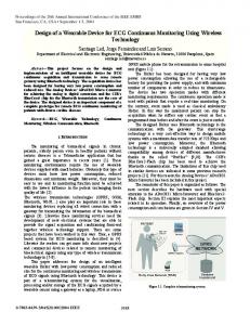
CR = 24 Figure 7. Plot of original and reconstructed of lead II record I12 at three different compression rates
MEAN PRD OF THREE DIFFERENT SCENARIOS Compression Rate 8 1.40 0.96 1.05
12 1.86 1.15 1.14
16 2.55 1.48 1.43
20 2.76 1.79 1.61
24 3.10 1.86 1.77
compression
Original
Fig. 7 shows plot of the first 5 seconds lead II of the original signal (record I12) and its reconstructed signal at 8, 16, and 24 compression rates using the 3:OR scenario. To help the visualization of the distortion of reconstructed signal compared to the original one, Fig. 8 shows plot of the residual signal. According to the Fig 7, the reconstructed signal retains the characteristics of the original signal at 8 and 16 compression rates. Plot of the reconstructed signal almost indistinguishable from the original signal. The characteristics of original signal starts to distorted at compression rate = 24, clearly visible on 110th, 130th, 270th, 540th, and 1270th samples. The residual signal of reconstructed signal at compression rate = 8 almost similar to a straight line. The perfect reconstructed signal will demonstrate perfect straightline signal. Start from compression rate = 16, the distortion of reconstructed signal became more visible. The effect of beat reordering and residual calculation were more significant as the compression rate higher. TABLE II.
the
CR = 8
Mean 2.12 1.34 1.30 CR = 16
B. Per Lead Evaluation To analyze the quality of each lead of the reconstructed ECG signal, we compressed single record in the dataset i.e. I01 at two different compression rates i.e. 8 and 16 using 1:N and 3:OR scenarios. Table III shows the PRD of each lead on each scenario at two different compression rates. The effect of beat reordering and residual calculation is not the same to all leads. For example, on lead I those optimization steps reduce the distortion by 27% and 9.5% at CR = 8 and 16, respectively. While on lead II, the distortion increased by 19.7% at CR = 8 after those optimization steps applied. But, at CR = 16 the distortion decreased by 21.4%. As can be seen on the table, in scenario 1:N the mean PRD at 8 and 16 compression rate are 2.51 and 7.87, respectively. After beat reordering and residual calculation applied, the mean PRD reduced to 2.24 and 6.02. Overall, the beat reordering and
CR = 24 Figure 8. Plot of residual signal of lead II record I12 at three different compression rates
C. Performance Comparison with Other Methods It would be unfair to compare the compression performance of various methods when each experiment is conducted under different condition such as different ECG database, different lead number, or different input records. Table IV shows performance comparison of various multilead ECG compression methods using different approaches 492
such as vector quantization [16], DCT [17][18], template based, Huffman, ADPCM [19], MPEG4-ALS [20], JPEG 2000 [21], or simultaneous matching pursuit [22]. According to Table IV, only the experiment by Martini [21] that has similar setup with ours. Therefore, we could only compare the proposed method with Martini [21]. Compared to Martini, the proposed method gives less distortion at higher compression rate. The PRD of the proposed method At CR = 14 is 4.58 versus ~6.60 at CR = 13.5.
REFERENCES [1] [2] [3] [4]
TABLE III. CR Lead I II V1 V2 V3 V4 V5 V6 Mean
TABLE IV.
PRD OF EACH LEAD OF I01 RECORD
Scenario 1:N 8
16
8
16
4.56 1.27 3.33 3.11 1.96 2.56 1.74 1.54 2.51
10.14 4.58 6.03 11.59 10.56 5.59 9.42 5.06 7.87
3.30 1.52 3.79 2.65 1.93 1.74 1.63 1.39 2.24
9.17 3.60 5.89 8.33 6.60 5.69 4.30 4.60 6.02
[5]
[6]
[7] [8]
PRD AT MAXIMUM COMPRESSION RATE OF VARIOUS MULTI-LEAD ECG COMPRESSION METHODS
Author
Database
Miaou [16] Prieto [17] Alesanco [19] Sharifahmadian [2] Sgouros [20]
MIT-BIH Arrhythmia CSE Multi-lead db MIT-BIH Arrhythmia MIT-BIH Arrhythmia MIT-BIH PTB Diagnostic db XAI Medica INCART Arrhythmia* INCART Arrhythmia** INCART Arrhythmia
Lukin [18] Martini [21] Qin Tan [22] Proposed
Scenario 3:OR
Lead num
Max CR
PRD
2 8 2 2 8
8.6 14 46.8 24 11.5
24.5 6.60 6.47 4.00
8 8 6 8
26 13.5 6.5 14
5.00 ~6.60