robust design optimization; bounding boxes; 3D optimization .... other 3D objects in Unity 3D Engine [4], [5]. III. .... 3: Manual definition of the centre of mass in "Race .... Learning, 2004. ... [17] J. Liberty and D. Xie, "Programming C# 3.0",. 2008.
3D tools for the Robust Design Optimization of an Autonomous Underwater Vehicle
Andrey Kirsanov*, Sreenatha G. Anavatti and Tapabrata Ray School of Engineering and Information Technology University of New South Wales Canberra, ACT 2600, Australia *Email: z3397566@student. adfa. edu. au
Abstract
This
development Design
of
the
describes
methodology
Optimization
Autonomous
paper
based
on
for
3D
Robust
tools
for The
Vehicles.
Underwater
the
specifications for the design are picked up from
design for variations around this. Nowadays, global industry companies align their production through approaches based on the minimum economic losses. One of the most effective methods is using RDO. This
method allows faster
design
creating the
the Scope Statement incorporating the mission
effective
requirements,
unmanned vehicle to suit the mission requirements.
including
the
guidance
navigation specifications.
The
incorporates
of
and
model for guidance and navigation of
methodology to
Today, 3D graphics is widely used during the
achieve the mission, the links, both internal and
build process. This paper uses this 3D technology
the
D atabase
components
external to provide a clash-free arrangement of
with
the components. Polygon Optimization is utilised
Underwater
the
RDO
for
for internal arrangement. Numerical results are
design process come from the mission requirements
presented for an actual case.
or the guidance and control requirements.
Keywords - Autonomous Underwater Vehicle; robust design optimization; bounding boxes; 3D optimization
based on the mission requirements by creating a
Vehicles.
designing The
Autonomous
specifications
for
the The
components that make up the AUV are selected Database of the available components. Assembly of complex systems and structures in I. The system
INTRODUCTION
development for
of
3D was proposed by Siemens Company as a part of
guidance
Autonomous
and
Underwater
(AUVs) is a challenging task.
control
Vehicles
This is due to the
non-linear dynamics of the AUVs coupled with uncertainty in operating conditions leading to time varying dynamics. One of the possible ways to get the
optimal
performance
from
guidance
and
navigation system is to design the vehicle with these specifications. Due to the changes in the operating conditions and the variations of the payloads, the solution may not be optimal for all the conditions. To
overcome this,
(RDO) is introduced.
Product Lifecycle Management (PLM) in early two thousand years [1]. Later, this technology has been supported by many other companies such as: Boeing, Dassault, etc [2].
The main disadvantage of this
approach is the lack of a mechanism that allows changing or adding the elements to the Database in build process.
The current
work
proposes
a
solution to this problem. The method is to create a phase-splitting process during the 3D assembly and flexible links between components in Database. This is used in the current paper.
Robust Design Optimization This
leads
to
optimal
condition for a particular case and nearly optimal
978-1-4673-6217-7/13/$31.00 ©2013 IEEE
The components need to be placed suitably to provide clash-free environment. This is achieved by
1730
using
Polygon
Optimization
during
the
clash-free placement of the components to achieve the required centre of gravity and buoyancy point locations.
THE DESIGN PHOLOSOPHY
II.
design
phase. Thus, the methodology provides an internal
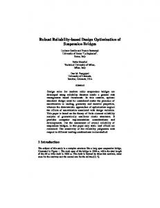
The fIrst part of this design method is the Scope statement. The Scope statement includes the whole process
of
project
organization
from
input
parameters of the AUV to the approximation of the
Section 2 provides the overall methodology of
cost of a program, project, or operation (Figure 1).
the RDO process. The selection of the D atabase is
This includes the specifIcations from
discussed in Section 3. Section 4 provides the links
point
between the different components.
requirements. We must create an algorithm which
The process of
of
view,
like
navigation
the mission
and
guidance
Polygon
can read the input parameters, work with Database,
Optimization is presented in Section 6 along with
create a component selection fIle, import objects
some concluding remarks in Section 7.
from another program tools, render the scene in a
assembly
is
discussed
in
Section
5.
real time, analyse the results of the project: � --------------------------
Input parameters:
Scope statement
Parameter 1
• Database of components
Parameter 2
0----
+
Parameter 3
Selection of components
+
Parameter N ---
------------------
Components optimization
---
+
--------------------------
Importing the AUV' s shape
Input components:
r---+
DC motor
from CATIA
+
Batteries
The assembly of components Board computer
in the 3D
+
Sensors ---
I
------------------
Generating the shape
Fig.
1:
Visual analysis of results
---
�
Robust Design Optimization, 3D assembly of components
The Database is collected from components, regardless of the fInal purpose of AUV but with
imports generated objects from CATIA to a real time 3D
engine
[3].
It' s
required
for
creating
and
some of restrictions, such as: dimensions, weight,
assembly
power consumption, etc. The Scope statement in
components, measuring grid, and other 3D objects
most cases is provided by the customer, and it
in Unity 3D Engine [4], [5].
depends on the area of work: industry, etc.
military,
science,
The next stage is the selection of
components from the Database.
If the necessary
component is missing in Database then it can be installed in the process. FBX format of 3D models
2013
the
3D
III.
scene
with
AUV' s
shape,
THE DATABASE
The Database created for the experiment with 50 different components can be used in robust
International Conference on Advances in Computing, Communications and Informatics (ICACCl)
1731
design optimization of the AUV [6]. All of these components have a wide number of parameters. The
full list of components is presented below: Table 1: The list of DC motors with planetary gear
Supply Rated tvoltage, orque, g'cm �
Model
IG16GM1 IG16GM2 RA20GM1 etc.
12 24 12
Rated speed, pm
5 9.7 22
dIe Power Radial �hrust Weight, urrent, p utput, play of play of � A �haft, shaft, W Plm P1m 0.01 100 0.39 50 0.09 l.03 0.01 100 50 0.09 0.1 l.5 0.02 150 50
Rated Idle current, speed, pm rnA
6270 10400 6700
85 90 200
8000 l3500 8000
Table 2: The list of Board computers
Model PCM-3343 PCM-3353 PCM-3355 etc.
CPU, MHz 800 500 366
RAM,
MB 256 1024 1024
SSD, GB 4 8 4
USB
COM
4 4 2
2 4 3
LAN, MB/sec 10 10 100
Power consumption, Watt 4.25 8.75 9.9
Table 3: The list of Batteries
Model
Type
DT12012 DT12022 DT12045 etc.
Pb Pb Pb
Voltage, V 12 12 12
Charge, A·h l.2 2.2 4.5
Size, mm
Weight, g
Volume, mmj
97x43x58 178x34x66 90x70x107
580 970 1600
241918 399432 674100
Table
Model
Resolution
KP-F33GV KP-F83GV KPF140GV etc.
656x494 1034x779 l392x1040
Pixel size, �m 7.4 4.65 4.65
FPS 90 36 30
Sensitivity, Ix 550 400 2000
All components listed above are designed for extreme environmental conditions, such as: deep underwater work, low temperature, chemical environment etc. IV. THE LINKS There are links between the parameters of components in these tables. These connections help
1732
2013
4:
The list of Sensors
eight, 1P0wer consumption, Control "hannel lWatt g 140 4 RS232 200 4.5 USB 220 USB 5
to determine the most effective selection of components, depending on the terms of Scope statement. Number of connections is not fixed and can be added as needed. All values in the tables are normalized before optimization process. The main selection parameters include: size, weight, power, capacity. All connections of components are presented below (Fig. 2):
International Conference on Advances in Computing, Communications and Informatics (ICACCl)
- - ---- - -- - - - -- - ---- - -- - - - -- - ---- - -- - - - -- - - - -- - -- - - - -- - - - -- - -- - - - -- - - - -- - ---- - -- - - - -- - ---- - -- -
Internal Links
r------------I I I I I I I I I I I I
DC
\ I
Motor r-----------I Board computer I I
Supply voltage, V
RAM, MB
Rated speed, rpm
SSD, GB
Rated current� rnA
USB
Idle speed, rpm
Idle current, rnA
COM
Power Output, W
Radial play of shaft, mm
Thrust play of shaft, mm
----
I
CPU, MHz
Rated torque, lUffi
I I I I I I I I I I
LAN, MB/sec
Sensor
Power consumption,
Resolution
Watt
Charge,
Pixel size, ill!l
!Vl
FPS Weight, g
---- )
Sensitivity, Ix
Weight, g
Power consumption, Watt
Control channel
I
,
,-
-
------------------
-------- - ---- - -- - -_____ ,1
,
I
r----
I I I
-
Weight
'
--
,
I
I I
Speed
:
I
--
Vehicle
:
l ____________________________________________ �
,------- - ----------------- - ------------------------- - ------------ - ------------------------- - --,
Fig.
2:
Flowchart of connections between components
v. ASSEMBLY PROCESS When the selection process of the components of AUV is finished, it is required to import objects (shape, components, etc.) into the Unity 3D engine [7]. This will allow us to visualize the assembly process of the vehicle. The best option to import 3D objects is to use the FBX file extension [8]. The FBX file extension is widely used in all known 3D engines and tools from Autodesk [9], [10].
1.
the Database 2.
2013
Bounding box creation for all components
(e.g. Collision detection) 3.
Finding the centre of gravity in each
component 4.
Components integration into the shape of
AUV 5.
Weight distribution of objects in the shape
of vehicle
The assembly process of the vehicle consists of several stages:
Selection of the necessary components from
Finding the centre of gravity in the component can
be
calculated
automatically
or
International Conference on Advances in Computing, Communications and Informatics (ICACCl)
specified
1733
manually.
For
aeronaut"
is
example, a
the
complex
object
model
"Race
for
400
manually specify the centre of mass. However, the object "DTI207" is rather simple and its centre of can
be
specified
using
the
By·0. 5, Bz·0. 5) ; Ceenter (Cx·0. 5, C y·0. 5, Cz·0. 5) ;
automatic
calculation of centre of gravity, and we have to
mass
Aeenter (Ax·0. 5, Ay·0. 5, Az·0. 5) ; Beenter (Bx·0. 5,
where A, B, C are boundary points of each edge bounding box.
automatic
calculation based on the bounding box [11], [12].
o Fig. 4: Automatic definition of the centre of mass in
"DTI207" Fig. 3: Manual definition of the centre of mass in "Race
Also, we need to divide the shape of AUV into
400 aeronaut"
several logical parts: nose, middle body, tail. Each
Automatic calculation of centre of mass uses the principle of the "Sweep and prune" algorithm [13]. Coordinates of required points (vertices) [14] are determined by the following calculation:
part includes a specific set of components from a Database. This means that in addition to the internal links between parameters of components there are external links between components and parts of AUV. All external links are shown on the Fig. 5:
SENSORS,
BOARD COMPUTERS,
digital,
PCM class
analog
BATIERIES, DT, DTM class DC MOTORS,
Fig. 5: External links in 3D view of AUV
External links are created after internal links.
the purpose of the AUV, we have several options for
The main purpose of internal links is parameters'
the design. For commercial purpose, the AUV could
optimization between each of components of the
be designed with maximum number of batteries in
vehicle.
middle part and low-power DC motors in the tail of
The
main
purpose
of
external
links
is
distribution in the shape of vehicle. Depending on
1734
2013
body. For military purposes the AUV could be
International Conference on Advances in Computing, Communications and Informatics (ICACCl)
designed with power pumps and protected PC [15] unit for hazardous body.
For
environment in
middle part
of
research purpose the AUV could be
designed with high precision sensors and power P C unit, sensors must b e located i n the nose section of the body. Parameters such as size and weight are read from the Database and are optimized for the selected shape. VI.
POL YGON OPTIMIZATION
Fig. 6: The model of AUV with
1924 points
The obvious approaches to collision detection for
multiple objects are very slow
[16],
[17].
Checking every object against every other object will ...
work, but it is not efficient with a big number of objects. Checking objects
- .
"
.
.
-
. "
.
'
.
.
�
.
with complex geometry
against each other in the obvious way, by checking each face against each other face, is quite slow itself [18],
[19].
During the creation of
the
j
assembly
.'
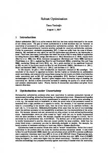
process, we need to consider the speed of 3D models calculation for real time software [20]. The task is to
Fig. 7: The model of AUV with
decrease the number of points (vertices) in 3D model with minimal loss of quality
482 points
but at an acceptable
speed of data processing [21]. For this purpose we created three types of the same AUVs model but with different number of points:
Fig.
8:
The model of AUV with
241
points Q) E c: o
......
OJ ::I OJ
---
-�
---
--
----
-------J
----- -- ----,
"
Fig.
2013
9:
diagram of the nwnber of vertices, components, and time (ms)
International Conference on Advances in Computing, Communications and Informatics (ICACCl)
1735
Using the diagram (Fig. 9), we can see that the optimal solution for the calculation of the ratio of time to the number of objects and vertices. For this study, the constraints posed are; a) The minimum number of components in the vehicle is five: one DC motor for propeller, one battery, one PC unit and two pumps (yaw and pitch). b) There is a limit on the size of the vehicle - no more than fifty components could be placed there. As the assembly process is required in real time, we must reduce the calculation time to the minimum possible value - 2500ms or 4000ms. Using these time restrictions, the number of vertices in the shape of AUV must not exceed two hundred and forty-one. One of the intermediate stages in the design is displayed in Fig. 10.
VII.
CONCLUDING REMARKS
The paper presents a methodology for RDO of AUVs. The overall specifications for the design come from mission requirements. The novelty of this approach is to optimize the Database of components, rendering the assembly process, replacing or adding the necessary elements on-fly, integration of 3D models to the system and reading all their parameters. This software tool can be used for the calculation and optimization of any type of unmanned vehicle for internal clash-free design with known centre of gravity and buoyancy point. The future work looks at developing a robust controller based on the hydro-dynamic properties of the designed vehicle.
..
All (oordinlt� lie with le�llo lin "Iuopitem Iot.Jt� at Ihe Nose tip 01 Sulf�t lIt.! Im"11. o.OIJl.n 01. Dls,pktmmt ¥Otume Im"'31 � O.OCIIkll 03 MU$ Qf ltw,.diSPi�w;lt� lIJ ... nl 04 TOI��'oftheIOY",b",oIII"illelil 4),,7" OSP,)�"I·J2U6 06 Cef\II e olGuYl1 v. CG.lmml - 0956994 01 �l"t 01 Q·�,,,t..,. CGyl ml'fl, _ 0 20507 01 Ct!nl'e 01 Gu.... ly. C G ' I mml 166.854 09.Ctt'lueoll��,Clltlmml"O IQ Ceflt'tolho¥Mq,C8y{mml_a 11 �"e oIlvoV�Y, C8111nmj_ 1 fi16'J 11 l�hofNosel"'ml 50 1).l�hof'.lIlmml
10
'4 l�hof Middle Body
Imml 24&.)6 alilenl1h Imml_ 31'.3' M,ulmWft diilR\f!lerlmml 57 no!
15 Qo..er Hi.
17 l/Drado_65S281 11 Innl!l diamel« of lhe pipe Imml 51.7401 19.1.en&th of Ihe mln WIne. ""Wlte Imml 11 of Ihe � alm,LAllmml 414967 21 LentTh of Ihc k:ver arm, W Imml 109 667 n � U,",ot: Inc rntthQd IHI 001.100" 2] Dnt uilnt Gillmer & Jhanson ITM!thod IN]'" 0.01:17107 2. � w,'I'C MI'r method IN) .. O.OUUl!o 20. le"l!h
Fig. 10: Program in the build process
1736
2013
International Conference on Advances in Computing, Communications and Informatics (ICACCl)
[15] G. Subrata, "8051 MicrocontroIIer: Internals,
REFERENCES [1] C.
Burchardt,
"High
Instructions,
Definition
Product
Programming
&
Interfacing",
2010.
Lifecycle Management an Immersive Decision Making Environment",
in Proceedings of the 23rd CIRP Design Conference, pp 61-70, March 2013. [2] D. Ghosh, "Robust Design - An Important Tool For
Business
Success"
in Proceedings of Structural Dynamics & Materials Conference, 2004. [3] A. Forrest, "Computational geometry",
Proceedings ofRoyal Society London, [4] S. Boyd and L. Vandenberghe, Optimization"
in
1971.
"Convex
Cambridge University Press,
2009. [5]
T. Nikodym, Interactive
"Ray Tracing Algorithm For
Applications",
University in Prague,
Czech
Technical
2010.
[6] J. Cohen and M. Lin, "An Interactive and Exact Collision Detection System
[16] R. Wang and X. Qian, "Open Scene Graph 3.0: Beginner's Guide", 2010. [17] J. Liberty and D. Xie, "Programming C# 3.0", 2008. [18] S.
Blackman,
"Beginning
Development with Unity:
3D
Game
AII -in-one,
multi
platform game engine", 2011. [19] G. Bradski and A. Kaehler, "Computer Vision with the OpenCV Library", 2008. [20] K. Engel, "Real-time volume graphics", pp. 112-114, 2006. [21] H. Barrow and J. Tenenbaum, "Interpreting line drawings
as
three-dimensional
surfaces,
Artificial Intelligence", vol. 17, pp. 75-116, 1981.
for Large Scale
Environments",
in Proceedings of ACM Int. 3D Graphics Conference, pp. 189-196, 1995.
[7] M. Lin and J. Canny, "A Fast Algorithm for Incremental
Distance
Calculation",
in Proceedings of IEEE Int. Con! Robotics and Automation, pp. 1008-1014, 1991. [8] E. Gilbert and D. Johnson, "A Fast Procedure for Computing the Distance between Complex Objects in Three-Dimensional Space", in Proceedings of IEEE Trans. Robotics and Automation, pp. 193-203, 1988. [9] W. Jones, "Beginning DirectX 9", Cengage Learning, 2004. [10] A. Thorn, "DirectX 9 Graphics: The Definitive Guide to Direct3D", 2005. [11] P. Shirley and M. Ashikhmin, "Fundamentals of Computer Graphics", Second Edition, 2005. [12] T.
Moller
and
E.
Haines,
"Real-Time
Rendering", 2007. [13] J. Cohen and K. Madhav, "I-COLLIDE: an Interactive System
for
and
Exact
Large
Scale
Collision
Detection
Environments",
Proceedings of the 1995 Symposium Interactive 3D Graphics (Monterey, CA),
in on pp.
189-196, 1995. [14] J. Chen and C. Chen, "Foundations of 3D Graphics Programming", 2008.
2013
International Conference on Advances in Computing, Communications and Informatics (ICACCl)
1737