A reference length parameter (REFL in NAME02) is also available to scale input and output coordinate data ..... RARRAY locations of ?ammeters to be printed. Titles to head ...... 215 ISUPRS - 1 = SUPPRESS PRINTOUT OF: A i STARTUP I N ...
NASA Contractor Report
165997
c I
i ,
&
THE CMC/3DPNS COMPUTER PROGRAM FOR PREDICTION OF THREE-DIMENSIONAL, SUBSONIC, TURBULENT AERODYNAMIC JUNCTURE REGION FLOW VOLUME I1 - USERS’ MANUAL
P. D. Manhardt
COMPUTATIONAL MECHANICS CONSULTANTS, INC. Knoxville, Tennessee 37920
Contract NAS1-15105 September 1982
W A
National Aeronautics and Space Administration Langley Research Center Hampton,Virginia 23665
CONTENTS SUMMARY
..................................
1
...............................
1
...........................
3
INTRODUCTION
CMC. DATA PROCEDURES
............................ Main Program . . . . . . . . . . . . . . . . . . . . . . . . . . . . . Namelist Control and Reference . . . . . . . . . . . . . . . . . . . . Geometric Description and Discretization . . . . . . . . . . . . . . . Simple Geometries . . . . . . . . . . . . . . . . . . . . . . . . . Complex Geometries . . . . . . . . . . . . . . . . . . . . . . . . Report Format O u t p u t . . . . . . . . . . . . . . . . . . . . . . . . . Dependent Variable. Boundary and I n i t i a l Conditions . . . . . . . . . . Primary Flow Parameter Tables . . . . . . . . . . . . . . . . . . . . . Solution Procedure . . . . . . . . . . . . . . . . . . . . . . . . . . Turbulence Modeling . . . . . . . . . . . . . . . . . . . . . . . . . .
DATADECKSTRUCTURE
EXTERNAL JUNCTURE CORNER SAMPLE CASE DATA
.................
............................. F1 ow-f i el d Geometry . . . . . . . . . . . . . . . . . . . . . . . . . . Boundary Conditions . . . . . . . . . . . . . . . . . . . . . . . . . . I n i t i a l Conditions . . . . . . . . . . . . . . . . . . . . . . . . . . Parameter Table . . . . . . . . . . . . . . . . . . . . . . . . . . . . Sol u t i on Procedure . . . . . . . . . . . . . . . . . . . . . . . . . .
Namelist Data
APPENDIX
A B C
D
. Automatic Discretization Refinement . . . . . Command Name Descriptions . . . . . . . . . . Scalar Variable Descriptions . . . . . . . . External Juncture Corner Data Deck L i s t i n g
i
. . . .
. . . .
...... ...... ...... ......
5 5 7 8 8 9 12 17 22 24
25 28
29 33 36 37 38 39 40 44 51 56
%I
SUMMARY
The CMC fluid mechanics computer program system i s being developed to transmit the theoretical evolution o f f i n i t e element numerical solution methodology, applied to nonlinear field problems into a v e r s a t i l e computer code f o r comprehensive flowfield analysis. T h i s report i s Volume I 1 of a three volume s e t and presents data deck procedures for the CMC threedimensional Parabol i c Navier-Stokes (PNS) algorithm. General data procedures are introduced, followed by detailed description of a juncture corner flow s t a n d a r d t e s t case data deck. A complete l i s t i n g of the d a t a deck i s given i n Appendix A , followed by a detailed explanation of g r i d generation methodology i n Appendix B. Subsequent appendices present descriptive tubulations of a l l commands and variables available t o the user. These a r e i n alphabetic order w i t h cross-reference numbers which refer to storage addresses. Volume I o f t h i s report i s referenced for d e t a i l s of the theoretical foundation, development o f the f i n i t e element 3DPNS algorithm, and discussion of results for the juncture corner t e s t case. The CMC computer program structure and description a r e detailed i n Volume 111.
iii
I NTROOUCTION Input f a c i l i t i e s f o r the CMC computer program a r e highly sophisticated and greatly simp1 i f y data deck preparation and modification. The program sequentially scans data deck card images and operates on comnand name data as encountered. Numerical data required f o r each command operation a r e i n p u t i n free format directly following the command card. Command operations can cause vectors t o be f i l l e d , i n i t i a t e a series of solution operations o r specify output formats and t i t l e s . Command card sequence i s quite f l e x i b l e and care has been taken t o ensure that most operations which must be performed sequent i a l l y a r e specifiable under one command name.
The CMC data deck i s d i v i d e d into seven sections f o r description. Exclusive of machine related j o b control statements, the seven sections consist of a FORTRAN MAIN program and accompanying subroutines (specific t o external corner flows), name1 i s t data, geometric description, o u t p u t format specification, boundary and i n i t i a l condition data and solution directing commands, see Figure 1. Each of these d a t a and i t s subset i s preceded by a command card image w h i c h d i r e c t s a program activity, and upon completion returns control t o the next comand data card. The program operates in a dynamic storage mode and the function of MAIN (data deck section one) i s t o allocate s u f f i c i e n t storage for the IZ a r r a y which i s internally sized as a function of the number o f f i n i t e elements requested for a specific problem. The namelist section of the deck (-section two1 is used t o specify scalar, integer and floating p o i n t d a t a u t i l i 2 i . n g the FORTRAN namelist option, The data a r e read i n namelists NMlECPI a n d NAMEW, respectively, and stored i n the arrays IARRAY and RARRAY. T h e geometric description section (data deck section three) contains data required t o generate a f i n i t e element g r i d suitable for the solution. Onedimensional and rectangular two-dimensional discretizations a r e formed by specification of g r i d refinement along the coordinate axes. More complex boundary shapes (nonrectangular) necessitate data specification along a l l domain boundaries and certain i n t e r i o r subdomain boundaries. Generated d a t a consist of g r i d p o i n t coordinates for each generated node and a node connection table which defines the f i n i t e element domains.
f
-
.
- .. .. . ._ _.
Solution Procedure
L
- _- ---.- .-
/Primary Primary Flow F1 ow Parameter Tables Tab1 es .
-
-.
'Boundary Boundary and I n i t i a l Conditions
i
IV /(;itput Specification Report Format O u t p u t
_____ -
- . I
Geometric Description __ . i s t -Control and Reference -.
I I ('Name1
-
_ A
Figure 1.-
2
CMCData Ddck Major Sections
CMC employs a h i g h l y a d a p t i v e output r o u t i n e which a l l o w s f o r data s p e c i f i c a t i o n of t h e s c a l a r and a r r a y v a r i a b l e s t o be p r i n t e d , s c a l e f a c t o r s t o be a p p l i e d t o each v a r i a b l e and t i t l i n g i n f o r m a t i o n t o head each v a r i a b l e l i s t . Each i s s p e c i f i e d under a command name i n t h e o u t p u t s e c t i o n ( s e c t i o n four, F i g . 1) o f t h e data deck.
The program operates i n nondimensional u n i t s and
data s p e c i f i e d s c a l e f a c t o r s a r e u t i l i z e d t o p r o v i d e f l e x i b i l i t y o f p r i n t u n i t s .
A r e f e r e n c e l e n g t h parameter (REFL i n NAME02) i s a l s o a v a i l a b l e t o s c a l e i n p u t and o u t p u t c o o r d i n a t e data t o a problem r e f e r e n c e l e n g t h .
I n a d d i t i o n , command
names a r e a v a i l a b l e f o r s p e c i f i c a t i o n o f problem i d e n t i f y i n g t i t l e s t o be p r i r . t e d a t v a r i o u s s t r a t e g i c l o c a t i o n s i.e., output.
a t t h e beginning o f each s e t o f p r i n t e d
The f i f t h s e c t i o n o f t h e data deck c o n t a i n s t h e r e q u i r e d boundary and
i n i t i a l c o n d i t i o n data which i s s p e c i f i e d a t t h e s o l u t i o n nodes.
The f i n i t e
element method e a s i l y handles mixed boundary c o n d i t i o n s , hence, b o t h f i x e d and Neumann t y p e a r e allowed. d i r e c t i o n ( i .e.,
Parameter t a b l e s , which a r e a f u n c t i o n o f t h e marching
a x i a l pressure g r a d i e n t ) a r e s p e c i f i e d i n s e c t i o n s i x .
Linear
i n t e r p o l a t i o n o f these t a b l e s determines t h e v a l u e o f t h e parameter a t each computational s t a t i o n .
The intended s o l u t i o n a l g o r i t h m i s i n p u t i n S e c t i o n
seven o f t h e data deck. V a r i a t i o n i n s o l u t i o n procedure i s o b t a i n e d through command c a r d i n p u t of t h e v a r i o u s program f u n c t i o n a l modules. Nonlinear, r e p e t i t i v e s o l u t i o n s a r e r e a d i l y handled by t h e L i n k c a l l l i s t which i s i n t e r r o gated a t each i n t e g r a t i o n step. The s e c t i o n s which f o l l o w g i v e examples of some o f t h e computer program f e a t u r e s which g r e a t l y simp1 i f y d a t a s p e c i f i c a t i o n and m a n i p u l a t i o n o f computed results.
These a r e followed by a d e t a i l e d d e s c r i p t i o n o f t h e data requirements
p e c u l i a r t o data deck major s e c t i o n s .
The data deck d e s c r i p t i o n f o l l o w s f o r t h e
s p e c i f i c j u n c t u r e flow caSe-9 i n c l u d i n g sample p r i n t and p l o t data.
CMC DATA PROCEDURES
Program f l o w i s c o n t r o l l e d by s e q u e n t i a l l y scanning t h e data deck i n 80 Subroutine BDINPT scans a c a r d f o r a command name and i n i t i a t e s a program f u n c t i o n f o r t h e given command. A l i s t o f t h e a l l o w e d acronyms i s g i v e n i n Appendix C. E i g h t columns a r e r e s e r v e d f o r t h e command names beginning i n c a r d column 1. Beyond column 8, o t h e r data such as non-
column increments.
dimensional i z i n g s c a l a r s o r c o n t r o l parameters associated w i t h a s p e c i f i c name
3
I f t h e f u n c t i o n o f a p a r t i c u l a r command name i s t o r e a d and
may be s p e c i f i e d .
s t o r e a s e t o f numerical o r l i t e r a l data, t h e cards c o n t a i n i n g t h e d a t a must d i r e c t l y f o l l o w the command card.
C o n t r o l i s r e t u r n e d t o BDINPT by t e r m i n a t i n g
a numerical d a t a s t r i n g w i t h a "TI' o r a " b l a n k c2rd"- L i t e r a ! d a t a are t e r m i n a t e d w i t h t h e word "DONE"
beginning i n c a r d column 1.
Most o f t h e numerical and l i t e r a l data, o t h e r t h a n command d a t a s p e c i f i e d i n the
Data d e l i m i t e r s may be
CMC i n p u t deck, may be i n p u t i n f r e e format.
blanks o r commas, thus a l l o w i n g f o r e s t h e t i c and meaningful arrangement o f numerical data.
Exceptions a r e n a m e l i s t data which u t i l i z e s t h e standard
FORTRAN n a m e l i s t o p t i o n and c e r t a i n s p e c i a l c a r d types which combine l i t e r a l and numerical data.
Several f e a t u r e s which g r e a t l y simp1 i f y s e q u e n t i a l and
r e p e t i t i v e d a t a s p e c i f i c a t i o n a r e a v a i l a b l e i n f r e e format. R e p e t i t i v e Numbers
R e p e t i t i v e Sequence
5*7.
12. -
F i l l s Array
For example:
7
12. 7. 7. 7. 7. 7 . 2 ( 5 . 2. 4.
(one per c a r d o n l y ) F i l l s Array R e p e t i t i v e Blanks ( A ) F i l l s Array Increment by a c o n s t a n t F i l l s Array Exponential N o t a t i o n F i l l s Array
4
5. 2. 4. 5. 2. 4 10. 12.
3*P
22.
10. 12. A A A 22. T
5*150 10
10 60 110 160 210 6. 10.E-2
14.E-4
6. .1 .0014
T
.
Solutions which proceed i n marching integration fashion may be restarted a t specific intervals by allocating f i l e space and specifying the command SAVETAPE i n the data deck p r i o r t o initiating integration. T h i s command causes a l l pertinent arrays t o be written on the s p , x i f i e d f i l e a t each solution p r i n t interval. File space i s minimized by specifying a small repeat number which rewinds the f i l e following the specified number of writes. For example: SAVETAPE
9
3
T
Save data i n u n i t 9
will cause the data arrays to be written on u n i t 9 a t each print interval. On the fourth write, the f i l e will be rewound before writing, thus obliterating the f i r s t three s e t s o f d a t a . A restart of the s o l u t i o n i s accomplished by issuing command RESTART. In this case the second integer indicates the data f i l e a t which t o s t a r t reading. For example: RESTART
9
1
T
Restart a t f i r s t s e t o f d a t a
will cause the f i r s t s e t of array data on u n i t 9 to be read into the storage arrays. Caution must be observed not to specify a r e s t a r t s e t of data which i s beyond the l a s t write indicated i n the i n i t i a l r u n . DATA DECK STRUCTURE Main Program : (CMC Deck Section I ) The function of MAIN ( F i g . 2 ) i s t o dimensionalize and i n i t i a l i z e the IZ, IARRAY and RARRAY arrays and call the control subprogram BDINPT. The IZ array resides in common block ARRAYS and contains a l l data array variables required for intersubroutine communication. The s i z e of IZ must be overestimated i n i t i a l l y since the arrays residing in i t are dynamically s e t i n the GO step as a function of specific problem size and solution type. On subsequent runs the s i z e may be adjusted t o f i t the problem storage requirements. Actual storage required by the program i s computed and stored (DECIMAL) a t location 100 i n the IARRAY array. T h e IARRAY and RARRAY arrays reside i n common block VARBLE and a r e utilized t o comnunicate scalar integer and floating point data, respectively, between subroutines and I / O . All 5cIC locations i n each of these arraysare printed upon encountering command ICOND, t h u s p e r m i t t i n g demand review o f the many keys and parameters utilized throughout the program.
5
CORNER(INPUTPOUTPUTIRSTRTITAPESXINPUTP *PROGRAM - - - c - T -A PME ~- = O U T- PcU T- I T- A-P E ~ = H S T R T )
C
COMMON / UARBLE / IARRAY(00500)r RAKRAY(00500) EQUIVALENCE ( IARRAY(00092)v I Z S I Z E COIIMON / ARRAYS / Iz(11oooo) COMMON L I S T ( 2 0 0 ) N Z S I Z E = 110000 CALL ERRSET ( 2 0 7 , 5009 - 1 r 11 01 217
C C C
100
CALL ZEROTK CONTINUE CALL RESET ( 0 0 5 0 0 ? IARRAYi 0 CALL RESET ( 0 0 5 0 0 ~ R A R R A Y ? 0 . 0 IZSIZE = NZSIZE CALL RESET ( I Z S I Z E I I Z P 0 CALL RESET ( 0 0 2 0 0 ~ L I S T ? 0 CALL EDINPT (30 TO 100
)
END
Figure 2. -
CPH: Main Program.
Namelist C o n t r o l and Reference ( CMC. Deck S e c t i o n 11)
A l l s c a l a r d a t a o f consequence a r e s t o r e d i n t h e a r r a y s IARRAY and RARRAY (Appendix C). Many o f t h e s e a r e FORTRAN n a m e l i s t s p e c i f i a b l e and a r e i n p u t under &NAME01 and &NAME02,respectively.
Namelist read i s i n i t i a t e d through
e
command FENAME which i n i t i a l i z e s a l l storage l o c a t i o n s t o d e f a u l t v a l u e s p r i o r c
t o reading namelist.
The n a m e l i s t t a b l e s a l s o c o n t a i n t h e name IARRAY and
RARRAY, t h u s a l l o w i n g d a t a t o be r e a d i n t o a l l 500 l o c a t i o n s i n each a r r a y For example, NEQKNN = 5, can
r e g a r d l e s s o f n a m e l i s t name s p e c i f i c a t i o n .
a l s o be s p e c i f i e d as IARRAY(58) = 5, under &NAME011 i n S e c t i o n I 1 o f t h e data deck. An a l t e r n a t i v e method of r e a d i n g data i n t o t h e s c a l a r a r r a y s i s t o use t h e IARRAY and RARRAY command names.
These can be i n s e r t e d anywhere i n t h e d a t a
deck, e x t e r n a l t o n a m e l i s t , and a r e useful f o r r e s e t t i n g p r i n t codes and dynami c a l l y c a l c u l a t i n g s c a l a r s t o be used i n subsequent steps. RARRAY
23
1.5142
s t o r e s a new v a l u e o f 1.5142
:ALC
T
-3
F o r example:
RESET TIME
i n t o l o c a t i o n RARRAY(23).
d i v i s i o n by ALC wh c h i s t h e v a r i a b l e s t o r e d i n RARRAY(3).
The ( - 3 ) i n d i c a t e s L kewise f o r i n t e g e r
data IARRAY
281
5048,
282
0,
283
71,
284
72
s t o r e s 5048, 0, 71, and 72 i n IARRAY l o c a t i o n s 281 t h r o u g h 2 8 4 , r e s p e c t i v e l y . Note t h a t these d a t a cannot be continued on f o l l o w i r i g cards. T h i s does n o t r e s t r i c t t h e method, however, s i n c e t h e n e x t card c o u l d c o n t a i n a s i m i l a r command. Dynamic d i m e r s i o n i n g i s accomplished by f i l l i n g t h e I Z a r r a y u s i n g t h e s i z e s p e c i f i c a t i o n NODE(decima1) as read under n a m e l i s t NAMEOl.
The command f o r t h i s
f u n c t i o n i s FEDIMN and i t must be completed f o l l o w i n g NAMELIST r e a d i n S e c t i o n I 1 o f t h e d a t a deck.
The dimensioning parameter NODE i s d i s c r e t i z a t i o n s i z e
o r i e n t e d and i s s e t s l i g h t l y l a r g e r than t h e number o f g r i d p o i n t s i n t h e solution.
.
The s t a r t i n g addresses of the dimensioned v a r i a b l e s i n t h e I Z a r r a y
a r e s t o r e d i n t h e f i r s t N I Z S ( i n rMMEOI) l o c a t i o n s i n I Z and a r e p r i n t e d i n decimal form i f KDUMP = 1 , i n NAMEOl
.
7
Geometric D e s c r i p t i o n
(CMC Deck S e c t i o n 111)
F i n i t e element d i s c r e t i z a t i o n o f t h e f l o w domain i s a u t o m a t i c a l l y generated from a coarse g r i d d e s c r i p t i o n . The p a r a b o l i c - e l l i p t i c form of PNS r e q u i r e s a g r i d o f space dimension one l e s s than t h e s o l u t i o n geometry. t h e r e f o r e , i s two dimensional.
The most complex g r i d d e s c r i p t i o n r e q u i r e d ,
A s o l u t i o n i s o b t a i n e d by "marching" t h e e n t i r e
two-dimensional g r i d i n a t h i r d space dimension w i t h s o l u t i o n dependent steps i z e forming a p a r t i a l a d a p t i v e g r i d .
Boundary shape changes a r e c o n t r o l l e d by
geometric t r a n s f o r m a t i o n parameters s p e c i f i e d i n data deck S e c t i o n V I and a r e r e f l e c t e d i n t h e s o l u t i o n through d i f f e r e n t i a l e q u a t i o n m e t r i c s . Simple Geometries
A r e c t a n g u l a r domain having g r i d l i n e s l y i n g p a r a l l e l t o t h e c o o r d i n a t e axes i s t h e s i m p l e s t geometry, and t h e r e f o r e , i s s i m p l e s t t o i n p u t . G r i d s i z e v a r i a t i o n i n each d i r e c t i o n i s accomplished u s i n g a geometric p r o g r e s s i o n o f f i n i t e element s i z e i n each d i r e c t i o n .
Yi+l
= Yo
I n t h e x2 d i r e c t i o n f o r example:
+
s
m+l
i-2
c P j=2
where p i s t h e s p e c i f i e d geometric p r o g r e s s i o n r a t i o and m i s t h e number of f i n i t e elements t o be generated i n t h e x2 d i r e c t i o n and scaled by S. Since i i n e q u a t i o n (1) i s always p o s i t i v e , p r o g r e s s i o n r a t i o g r e a t e r than u n i t y w i l l form a g r i d which becomes c o a r s e r as x 2 increases and p equal t o u n i t y forms a u n i f o r m l y spaced g r i d . The e q u a t i o n i s a p p l i e d piecewise o v e r t h e elements a l l o w i n g d i f f e r e n t p r o g r e s s i o n r a t i o s over each segment. For two-dimensional domains, e q u a t i o n (1) i s a p p l i e d s i m i l a r i l y i n t h e second d i r e c t i o n . The data d e s c r i p t i o n f o r r e c t a n g u l a r d i s c r e t i z a t i o n s proceeds by f i r s t s u b d i v i d i n g the domain i n t o s m a l l e r r e c t a n g l e s
(subdomains) each o f which
may have a d i f f e r e n t p r o g r e s s i o n r a t i o i n each c o o r d i n a t e d i r e c t i o n .
The f o u r
subdomain casab i l l u s t r a t e d i n F i g u r e 3a admits a f i n e d i s c r e t i z a t i o n along t h e s o l i d s u r f a c e and i n t h e t i p r e g i o n .
Data f o r t h i s case appear a s f o l l o w s ,
14
L I NK2
VXlSCL -5.0,
5
0.
- 8,
10
1.0
1.25
T
-4.0,
5
0.
*
8,
10
1.o
1.25
T
VXZSCL NDECRD
1
16,
1
16,
0
T
ELEM DON E
The f i r s t card i s the discretization comand card which effects a call t o s u b r . DSCRTZ. The VXZSCL and VXlSCL commands read the subdomain d a t a for the respective x ? and x 2 directions of Figure 3 ( a ) . Each data string contains f i r s t coordi'nate, number of elements t h i s subdomain, l a s t coordinate t h i s subdomain, a n d , progression r a t i o . Since the subdomain must be contiguous, the f i r s t coord-inate of subsequent subdomains coincides with the l a s t coordinate o f the one preceding i t a n d , therefore, i s not repeated. The NDECRD command admits a choice of grid refinement to be used for solution, and generates the g r i d points, The d a t a indicate f i r s t node in the x 2 direction (Fig. 3 ( a ) , l a s t node i n the x z direction, f i r s t node in the x3 direction, a n d l a s t node in the x 3 direction. I n the example, 15 elements a r e described i n each direction ( V X l S C L ) a n d (VXZSCL) a n d , hence, (1 16) will yield a l l elements described. I f , however. only the upper half of t h e discretization were desired for a particular solution, the NDECRD data would appear as ( 6 16, 1, 1 6 , 0 T ) . The ELEM command causes the f i n i t e element node connection table t o be formed. The number of elements and nodes generated (NELEM and NNODE) in IARRAY are determined and stored automatically i n the discretization process. The number of generated nodes must be less than NODE specified i n Namelist NAMEO1. Complex Geometries Secondary flow geometries having boundaries of general curvature and mu1 t i p l e discontinuities require a more sophisticated approach.
The CMC m u 1 tidimensional g r i d generator employs a local parametric coordinate transformation technique over independent quadrilateral and triangular segments of
9
t
1.0
x2
0.
-4.0 1.0
-5.0
F i g u r e 3a.
/I,.
Rectangular Domain D i s c r e t i z a t i o n ( F l a t P l a t e )
/
Figure 3(b).
-
F i g u r e 3.
10
I r r e g u l a r Domain D i s c r e t i z a t i o n
-
Flow Domain D i s c r e t i z a t i o n ,
.
the solution domain. A refined g r i d is generated over each local (single curved) subdomain and transformed into the global geometry. Figure 3( b ) i l l u s t r a t e s the method f o r a viscous corner flow problem where the potential core forms a curved boundary. Here four isoparametric quadrilateral subdomains having biquadratic variation a r e used t o generate the two-dimensional t r i a n g u l a r mesh (see Appendix B ) . T h i s method requires the specification of only coordinates i n any order and a subdomain connection table. The connection table order i s : corner g r i d points, side g r i d points counter-clockwise starting anywhere. A local coordinate convention i s used to order the generated d a t a . The origin is the f i r s t g r i d p o i n t i n the connection table, the abscissa runs along side 1, between the f i r s t and second g r i d p o i n t s i n the table and the ordinate runs along side 4 between the f i r s t and fourth g r i d points i n the t a b l e . T h e generated discretization i s ordered i n adjacent rows r u n n i n g between sides 4 and 2 beginning a t the l o c a l origin. For example, i f subdomain 1 i n Figure 3(b] i s numbered 15
1
3
17
,
10
2
11
16
a n d 5 elements per side were requested, the generated nodes would be numbered 1 t h r u 6 a l o n g side one (15 l ) , 7 t h r u 12 along the adjacent row, etc. Note i n Figure 3(b) t h a t the number of generated elements along side (3b) must be the same f o r subdomains I and I 1 i n order t o m a i n t a i n nodal connectivity among the generated elements,
The nonuniform g r i d exhibited i n Figure 3(b) i s obtainable u t i l i z i n g two d i s t i n c t l y different approaches, The f i r s t method involves movement of the subdomain side g r i d points ( F i g . 3 ( a ) ) toward the region of refinement, Since the number o f generated nodes I S equally distributed a b o u t the side node, a g r i d compression occurs f o r off-center side grid points resulting i n a smoothly skewed g r i d over an e n t i r e subdomain. T h i s method allows f o r great f l e x i b i l i t y and control over spacial distributions o f generated g r i d density w i t h minimal
i n p u t . The second method involves additional specification of geometric progression r a t i o s along subdomain sides and setting scalar variable JPR = 1 i n the IARRAY array. T h i s separates the grid refinement specifications from geometry i n p u t , t h u s p r o v i d i n g a means for changing g r i d refinement w i t h o u t having to locate a new geometry point. I t also overcomes, a t l i t t l e expense,
the further drawbacks of method 1, involving nonuniqueness and boundary shape inaccuracies of highly skewed discretizations.
11
To use t h i s o p t i o n i t i s necessary t o s p e c i f y t h e number o f subdomains (NSELEM) and g r i d p o i n t s (NSNODE) i n Namelist NAMEOl.
Node must a l s o be s e t i n NAMEOl l a r g e r than t h e number o f nodes being generated. Report Format Output
(CMC Deck S e c t i o n I V )
The o u t p u t s e c t i o n o f t h e CMC p r i n t formats.
data deck i s devoted t o o r g a n i z i n g t h e
Several p r i n t command names a r e a v a i l a b l e , each having a
d i f f e r e n t function.
Table 1 l i s t s t h e p r i n t commands and g i v e s a b r i e f des-
c r i p t i o n of t h e f u n c t i o n o f each.
Cards f o l l o w i n g t h e COMTITLE command a r e The command DESCRIPT 204 s t o r e s
read and s t o r e d f o r p r i n t on command
problem i d e n t i f y i n g t i t l e s f o r p r i n t a t t h e beginning o f each o u t p u t header. The v a r i a b l e s p e c i f i e d p r i n t formats i n
CblC a l l o w t h e user t o a r b i t r a r i l y s e l e c t and t i t l e t h e s c a l a r and a r r a y v a r i a b l e s t o be p r i n t e d . Scalars a r e n o r m a l l y grouped t o g e t h e r i n a header p r i n t which precedes p r i n t o f t h e v a r i able arrays. t o fit
The t i t l e s a r e i n p u t under command DESCRIPT 332 and a r e f o r m a t t e d
5 t i t l e s per card w i t h 16 c h a r a c t e r s ma~:ir~iuiii per t i t l e .
The s c a l a r
v a r i a b l e s associated w i t h each t i t l e a r e i n p u t under command IONUMB. data c o n s i s t of
These
i n t e g e r s i n d i c a t i n g t h e l o c a t i o n s i n RARRAY t o be p r i n t e d .
M u l t i p l i e r s t o be a p p l i e d t o each p r i n t e d number a r e l i k e w i s e i n p u t as i n t e g e r RARRAY l o c a t i o n s f o l l o w i n g t h e comnand MPARA.
The example below i l l u s t r a t e s
t h e i n p u t which p r i n t s v e l o c i t y i n t h e English, MKS, and CGS systems o f u n i t s : DESCRIPT
332
VELOCITY
FT/SEC
METERS/SEC
CENTIMETERS/SEC
DONE
IONUM -1 200,
3*27
T
MPARA -1
2*2,
164,
163
T
The DESCRIPT 332 comnand s t o r e s t h e four t i t l e s i n t h e o r d e r read.
The v a r i -
a b l e t o be p r i n t e d under each t i t l e , i n t h i s case RARRAY (200) = 0.0 and RARRAY
( 2 7 ) = Urn , a r e l i s t e d under t h e IONUM command and zeros a r e p r i n t e d as blanks.
12
Table
1
Print Commands
Command
Function
COMTITLE
Reads t i t l e w h i c h i s printed below the CMC!
DONE
Terminates 1 i teral d a t a
DESCRIPT 204
Sol ution pri n t heading
DONE
Same as above
DESCRIPT 332
Sol ution print parameter t i t l e s
MPARA -1
MRRAY locations of mu1 t i p 1 i e r TO BE APPLIED TO PARAMETER PRINT
IONUMB -I
symbol
RARRAY locations of ?ammeters
t o be printed DESCRIPT 203
T i t l e s t o head dependent variable print
IOSAVE -1
List o f dependent variables t o be pri n ted .
IOMULT -1
List o f locations in RARRAY o f m u l t i p l i e r s t o be applied t o each dependent variable
The p r i n t e d s c a l a r s a r e scaled by data i n RARRAY l o c a t i o n s s p e c i f i e d under t h e
MPARA command. I n t h e example, t h e r e f o r e , Urn i s p r i n t e d t h r e e times, scaled by RARRAY(2) f o r p r i n t under heading FT/SEC, scaled by RARRAY(l\64) f o r p r i n t under heading METERS/SEC, etc.,
where t h e m u l t i p l i e r s a r e 1.0,
and f e e t t o centimeters conversion f a c t o r s .
f e e t t o meters
A t y p i c a l header p r i n t o b t a i n e d
upon comnand LINK2 6 i s i l l u s t r a t e d i n F i g u r e 4, t o g e t h e r w i t h data d e s c r i p t i o n which c r e a t e d i t . Note t h a t t h e ( x - x - )
i n F i g u r e 4 p r i n t i s s p e c i f i e d as
999 under command IONUMB. T i t l e s heading t h e p r i n t o f a r r a y v a r i a b l e s a r e i n p u t under comnand DESCRIPT
203.
I n p u t format i s 16 columns p e r t i t l e , 5 t i t l e s per card;
i n p u t f o r each v a r i a b l e t o be p r i n t e d . heading a r e assumed "ODE
1 title is
The a r r a y s t o be p r i n t e d under each
l o n g and f o l l o w command IOSAVE.
The program a r r a y
variable/names a r e s t o r e d i n t h e f i r s t N I Z S l o c a t i o n s o f t h e I Z a r r a y and a r e described i n t h e Section V data deck d e s c r i p t i o n f o l l o w i n g .
M u l t i p l i e r s used
t o d i m e n s i o n a l i z e t h e p r i n t a r e s p e c i f i e d f o r each v a r i a b l e f o l l o w i n g command IOMULT.
I n t e g e r s p e c i f i c a t i o n o f RARRAY l o c a t i o n s i s used as described above
f o r scalarildata p r i n t . P r i n t format c o n t r o l i s o b t a i n e d f o r a r r a y p r i n t i n q t h r o u g h n a m e l i s t data specification. NPRNT i n NAMEOl.
The maximum number p r i n t d i g i t s a r e s p e c i f i e d i n IARRAY(20) = Output f i e l d s i z e i s c o n t r o l l e d by s p e c i f y i n g t h e r e q u i r e d
d i g i t accuracy i n IARRAY(22).
Output f o r a t y p i c a l case having simple geometry
i s i l l u s t r a t e d i n F i g u r e 5.
The format assumes l e a d i n g decimal p o i n t mantissa [not p r i n t e d ) and t h e exponent i s p r i n t e d once f o r each v a r i a b l e d i r e c t l y
f o l l o w i n g t h e a r r a y name. The p r i n t form r e f l e c t s problem geometry and approximate c o o r d i n a t e s a r e t a b u l a t e d on t h e abscissaand o r d i n a t e of a C a r t e s i a n r e c t a n g u l a r system f o r each v a r i a b l e p r i n t e d .
Coordinate values a r e i n reference u n i t s and a r e r e a l
numbers w i t h assumed l e a d i n g decimal as d e s c r i b e d above.
14
LIESCRIPT 332 T IOPAR PARAMETER T I T L E S FOR OUTPUT. REFERENCE ENGLISH-FT ENGLISH-IN M-K-S LENGTH......... .FT......... .IN.. .ti.,........ VELOCITY....... ,FT/S....... .N.A. .n/s........ DENSITY........ .LBM/FT3*... .N.A.*..*..+ KG/t43....... TEMPERATURE. .RANKINE.... .N.A. .KELVIN..... ENTHALPY....... .BTU/LBM. .N.A.. .KJ/KG...... FROZ.SPEC.HEAT. .BTU/LBM-Re. .N.A........ .KJ/KG-K.... VISCOSITY...... .LBM/FT-S... .N.A. 8 . . .NT-S/MZ.... LOCAL PRESSURE. .PSF........ .PSI.. * 'KNT/M2. + LOCAL SOLUTION. .MACH NO,.,. .DPDXl.. .ENERGY..... .H21...,.... aG22.e .G23........ T2PFIX..o...... NWGEOM H'S....* .H31....,... .G32.. .G33..+..... .DXLM/LREF.. .EPSILON.. Xi/LHEF....n... .DXl/LREF,. + DONE WPARA -1 5t2r 2 2 162 164 163, 3 8 2 1 6 4 163, 3 8 2 170 1 7 4 r 165 2r 2 - 1 7 5 3 * 2 r 3 8 2 1 7 6 2, 3$2 1 7 7 1 7 8 r 3$2 2 2 1 6 9 168 1679 3 * 2 108 2r 5*2r 5*2r 5*2 T IONUtiB -1 999t 5*200r 999s 200 4843, 200 27 200 27 2 7 1 200 10 2 0 0 10 101 200 58 200 58 2 0 0 r 200 9 7 200 97 2 0 0 r 200 3 0 200 30 200, 200 3 8 300 38 3 8 r 9991 3 9 4 f 3 6 r 300 154 100 135 1 2 2 s 3 9 8 4 * I l 186r 700 4 a I l 139. 11 12 14 A 5 47 T
....... ....... ....... ...... .... . ...... ..
...
4(a).
REFERENCE
- Header
ENGLISH-FT
C-G-S
.cn,........ .cn/s.......
G/CC....e* .N.A........ .N.A........ .N.A...*.... .POISE...... +TORR....... .INT. VAR... .Fl.......... .Gl.....+... .REFL RE NO.
.
P r i n t Format Data.
ENGLISH-IN
ti-K-S
C-G-S
x - x - x - x - x - x - x - x - x - x - x - x - x - x - x - x - x - x - x - x .ti.....,.... .cn.....,... .IN.. .FT LENGTH.........
.........
VELOCITY....... DENSITY........ TEMPERATURE.... ENTHALPY *.
s
.
.......
......
1000000Et01 .FT/S....... 1000010Et03 .LHti/FT3.... 2330814E-02 *RANKINE.+.* 5300000Et03 .BTU/LBtie. 1760684Et04 .BTU/LBM-R.. 7721760Et01 .LBti/FT-S... 4074412E-06
1200000Et o 2 .N.A.. .N.A........
.N*A+.
..
e.
.N.A........
3048000Et00
,n/s........ 3048000Et02 KG/t43....... 3733965E-01 ,KELVIN..... 2944444Et03 .KJ/KG...*.. 4092533Et04 .KJ/KG-U. e . . 3230784Et02 .NT-S/H2.... 6062725E-06
3048000Et02 .CM/S....... 3048000Et04 G/CC...... 3733965E-04 *N.A........ .N.A........
....... ...... x - x - x - x - x - x - x - x - x - x - x - x - x - x - x - x - x - x - x - x .... , .. .... . FROZ.SPEC.H€AT. VISCOSITY......
LOCAL PRESSURE. 9964654EtOO LOCAL SOLUTION. 0 Et00 TZPFIX......... 0 EtOO NUGEOti H'S..... Xl/LREF,..+.... 1100000E-01
.Ne&.
.N.A..
.F'SI....
.PSF.,...... 2116800Et04 .MACH N O . . . . B861539E-01 .H21........ 1000000Et01
1469906Et02 .IIPDXl.. 0 EtOO eG22. s + 0 EtOO eG32.s.. 0 EtOO ,EPSILON. t e e 1000000E-01
.
.H31*....*.. 1000000EtOl .DXl/LREF... 1000000E-02
KNT/ti2...... 1013524Et06 .ENERGY. 5847034Et00 .G23........ 0 EtOO .G33........ 0 Et00 .DXlM/LREF.. EtOO 0
.N.A........ .POISE.+.... 6062725E-05
.TORR....... 7601429Et03 . I N T . WAR... 0 EtOO .Fl*......... 0 EtOO .Gl.......*. 2129497E-14 .REFL RE NO, 5720616Et06
- x - x - x - x - x - x - x - x - x - x - x - x - x - x - x - x - x - x - x - x x - x - x - x - x - x - x - x - x -OF N0
4(b).
Figure 4.
-
- Typical
Nt 0
PASSES 1
PRINT 0
100
Header P r i n t .
Solution Header Data and Print.
15
PI
0
P
n .4
m
mnm
Q 0
I
.4
QnP
0.
0 0 0
r\
X I
d
X
m
PI-
0
0
0 0
m
I
R
0
m n
a
0.
N
b
n
X
0. 0. d
I X
h
I
0
.a
N
Q
n
w
0 4
ac
I
X
0 0 .
Q
0
0
o r \
I
0 P
N
Q
0
rd 0. d
%
4 n
nn
0
. I
99
r\ 0
N
0 0
h
n
0 0
0 PI
4.4
4
e m
0
0 Q
0
0
2
+ ,
0
n
s
4
0
0
cd
d
4
o
4
0
.
4
0
Q 0
r4
X
2 0.
m
I
X
0.
I
0
0. 0
h Q PIh 0 0
m
.4
0. PI
X
P)
I
Ul Li)
m
X
m
I
0
c
hh 0 0
.4
aJ
a
0
0.
PI N
I
kl
I
0.a
m 4 .p 4 I
0.
Q
Ul
0. P
4
0
.4
0 . 0 . P I N 4
.
0.
0.
0.
0
0 4
0.
4
4
n4
p\
W
fir\
0 0
0
0
.4
c
L li
.z
E
aJ a
Ill
0.
c,
Li) q-
X
X
.-VL
Ln
I-. P
0 e-
c
w m w r \
. I N
,.
-
4
0
m
m
m
9
L1
(I
4
.4
m
m
4
0
n
+
N
w
m
d
4
4
m a 0 - m
0
0
0 0
0
'.?
t-
LL PI
h
r \ o n
F.
4
d
0
LL
*P
C
.4
o
0
Y
. I
r
0
w
4
ul iL
r
9
Q Q
4
4
\
Q
0
Q N
Q
o
9
.4
4
0
.4
0
*
m
o
0
n 0. - I n m o 0
-
X
0
I
4
X
W
a
r
3 Z
X
iL 0
1
U
4
x
X I
.
x I
16
0
s
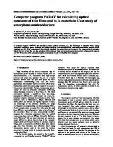
In addition t o the f l e x i b l e format p r i n t described above, other less f l e x i b l e print may be obtained which provides i n p u t validation and verification of problem definition. S e t t i n g KDUMP = 1 i n NAMEOl will e f f e c t a l i n e by l i n e data deck reflection, including each comnand card and i t s associated data a s read. Figure 6 i l l u s t r a t e s typical data verification p r i n t . Comnon data errors such a s not specifying "T" o r blank card delimiters a r e e a s i l y detected since the reader will continue t o read cards, including comnand names, u n t i l i t encounters one of these. The p r i n t subsequently appears a s continuous data reflection of a l l the cards under the original comnand name. Scalar data stored i n the arrays RARRAY and IARRAY ' a r e p r i n t e d by inserting the command ICOND. Figure 7 i l l u s t r a t e s the p r i n t format. T h i s p r i n t provides verification of the namelist data specification, and program computed s c a l a r s which a r e stored i n these arrays. Upon c a l l t o QKINT, a series of prints i s i n i t i a t e d . The f i r s t , i l l u s t r a t e d i n Figure 8, p r i n t s the variable numbers and types i n the solution. I f a res t a r t u n i t i s requested, the u n i t number i s p r i n t e d . The order of c a l l s f o r solution process i s l i s t e d and identified, followed by the variables and mult i p l i e r s t o appear following the header page a t each DELP solution p r i n t interval. Following this p r i n t , a c a l l t o ICOND i s i n i t i a t e d t o p r i n t the RARRAY and IARRAY s c a l a r l i s t s . This i s followed by a node map p r i n t which matches node numbers w i t h their coordinates. A subsequent standard solution p r i n t , a s described above, i s output which l i s t s the specified and default i n i t i a l conditions. Description of various debug print which i s useful f o r verifying algorithm correctness and debugging the program i s given n Volume I I , the Programmer's guide. Boundary and I n i t i a l Condition Specification
(CMC Deck Section V )
CMC admits the simultaneous solution of mu1 t i p l e d i f f e r e n t i a l equations.
Dependent and parameter array variables a r e stored sequentially, b e g i n n i n g a t the address stored in IZ(48) and a r e input i n a r b i t r a r y order following command IPINT. The number of d i f f e r e n t i a l equations, hence, number o f dependent variables i n a solution i s specified by NEQKNN i n NAMEOl, and the t o t a l number of variables specified i n IPINT is i n p u t in NEQ. Each specified variable i s actually a composite number which i s decoded by the program f o r identification.
17
d
h
N
m I h
N
Q)
m e N 4 4
Q)
e N m I
v1 N
2 e
1
1
1
hhh
d N m
hhh
mmm deb OD-
eco NN h I
u
.
w V
u
Y
l
s+
V
w
Y
s+ h
F
Z
Z
N
N
N
m
Y
e
w Y w
C
1
P
1
e
In Y
v
0
N
w C w
n
w
a
h
m
JJ
n
w
m
n
u
s+
w v1
w
L
n
w : w
1
e
*I-
b
e
t x
u m
I
4
h
N
m
a)
d
N
m
u w m
u
v
w
)
w
La
h
c
2 h 4
0
N
I-NN44
18
b
N
STATUS OF I a m A Y VALUES.
1 6 11 16 21
26 31
36 41 46 51
56 61
A6 71
ND LODG NPTDOF NNOUE NROW kOUNT NEO NPRSCC N2WAhE NF NDbL NtiOUTZ KDUHP NRHOSS ISTATN
7h 8 1 IVWVAL 85 hPNT 91 NZZ 96 IHASE
= = =
= = = =
1
o
1 190 2 1
8
=
0
= =
0
= = = =
0
= = =
=
4
0 0 0 0 0 .
0 1 4 200
101 NPRESS 106 KK 111 InAx 116 I G I N I T 121 NSPEC 126 ISPEED 131 NbORD 136 KSAV 141 KFSL 1 4 6 NSFDbE 151 KWFLXS 156 ITWRCL 161 NPVSX 166 N3IJFNS 171 NBCND 176 NTkS 181 NVELP 186 ITDA 191 NH 196 ITWALL
= = = = =
NSTRFP NHDL IHIDRV ITF'SCL NCYL
= =
IADSET NSAF NUAhE NLC NSNODE IF'C IbC JSIDE IFRINT NUS IVYY NEOAV2 5PR IPCOEF
=
1 8 0 0 0 0 0
=
0
=
0 0 1Y 0 0 0 0 0 0 1 1 0
301 NIHPCT 306 NMRJAC 311 JORDER 316 NIT 311 IPRNT
= =
201 206 211 ?16 271 226 231 236 241 246
151 256 261 266 271 276 781 286 191 296
=
= = =
= = =
= = = =
= = = =
=
= = 5
= = = = =
= =
= = =
=
=
= =
376 331 NCONSV 3 3 6 NPDSUG 34 1 3 4 6 NSPRED
= = i
=
2 Hl.ltIIF 7 Knit5 11 NCC 17 NNS 27 NE 27 NSKlF 32 IWI SEF' 37 NEWPRT 42 INPUT 47 LG 52 hROU 57 I A S V E C 62 N T I T L 67 NS 7 2 IVALUE 7. 7 . 82 I V S T A 07 NRTAFE 92 IZSIZE 97 ITKE
0 107 19 107 9 112 0 117 4 122 0 127 52 132 0 137 0 142 1 147 0 152 0 157 2660 162 0 167 194 172 10 177 0 182 0 187 3 192 0 197
202 207 212 217 227 227 232 237 242 247 252 257 762 267 272 277 282 287 792 297
1 302 4 3 7 0 307 1 312 1 317 0 322 0 327 0 332 4 0 337 0 342 0 347
hOUr NElE2 NUALLS IbUGl IWhIT IDIFRT IFWRIT
LPSIAl NOUTPR NPAST INIThE NFASS IEPSET KNTF'AS LOWD NU2POS LOGS ITDb N3l NTPRNT NSTRF IbOT HLTRHS NOPSCL
= = = =
KShIP
3
0
13 1R 73 28 33 38 43 48 53 50 63
=
0 8 193 19
=
0 5
=
=
-
1Y 46 0 3 26 0 0
=
0
= =
= =
= =
o
= *OOOO = 1 3
= = i :
= =
=
* = = =
= = = -i
--
=
E
= =
= = =
=
-
r
NPHOD NARFF'R INAF NEG NSELEH NFLUX NDCNT hTE
0 2
=
= =
= = = = = =
NPTS NV NEQAV3 JCYL IPPSET
=
NHCNTR NCONV IUONLY NDbGPT ISTART IDDXST JACSAV NTRLST
= =
= = = =
0 0 4 0 0 -2 -12 0
68 0
=
2
=
0 0 0 1
=
-
I
103 108 113 118 173 178 133 138 143 148 153 158 163
1 4 203 3 208 1 213 0 218 0 223 0 228 200 2 3 3 0 738 0 243 1 248 2 353 0 ?513 0 203 0 ?hB 0 3?3 101 7 7 9 0 283 1 788 0 793 0 3 8
=
=
NCLIORD NPART NR IPASS NBUG NOUIVC NEOADD NtIOF NH2 NEQKNN NIND 68 N1 73 ISTAD 78 83 IFSLT en NLINE 93 NTK 98 IHAT
0 0 0 200 168 1 173 3 178 0 183 0 188 6 193 2 198
0 0 4 3 0
a
IfiOW 8 hFfiINT
MTH NCNADD KPLVAR IBUG2 IGAS ICNTND
ITOP
= = =
= = = = = = = =
=
-
=
= =
= = = =
= = =
=
-
LPSIAH ICALLJ NONC NPUNCH INITCN NFSIST NDPRES NCOtlOC NU3F'OS IRSLHS NBUF NH2 NFGHDT
=
NTCHDH NVRHS IPHIPR NCLFSI MLTLttS
= =
NODES NSHAPF NODFT KFIX JCOLlKD NFX LOCR NDIVHF NSTAG NNPT NO1 NSORC IAXSYH NPSETS
3 0 3 NITER 3 0 8 N3HROW 313 NR 3 1 8 KkSKIF 313 NLAST 3 2 8 NUISC 3 3 3 JNOCRN 338 3 4 3 NOD023 348
Figure 7.
=
-
= = = =
= =
= = = =
=
1 0 0 2 4 0 0 10 -2 0 0 5 1047 4633 0 0 0 60 2 1
= = = = =
0
=
0 0 0 190 0 0 0 0 0 0 0
= = = = = = = = = = =
= = = = =
=
-
=
=
1 0 3?5 171
NPTEL IRUN LPRINT NIIRVDX NSTORE NOEL NHt4AL.F NCPTAH NSH NBSET IRRAY NO0 NVARD NEHD NIZS
3
14
7Y 34 59 44
49 54 59 64 69
74 79 84 89 94 99
0 104 8 109 0 114 0 119 0 124 190 129 4 134 0 139 0 144 0 149 0 154 0 159 0 164 0 169 0 174 3 179 0 184 0 189 9 194 4 199 1 8 0 7 3 0 170 0
=
4 hFYHliJ 9 NRSlRT 1 4 NFLEM 19 HOE
3 0 1 10 0 0
9 172 349 250
ImL
1
NFLIF' NlAPER HSSIJ NGBUO NDERIV IHAiAb NPSIbD INGAS ITRnN
1 0 0 0
IT NSDFCF IL NPSIND KCIJC NCOHTD LOC NGTPRS NSTIJ NUF' NPGRDV
2 0 4 INTOHO 209 NbIFRS 214 LHLT
21Y
KR
224
ILHS
279 1 3 4 KNTAKr 239 NAKF 2 4 4 N0i;lfiT 249 JSHF' 154 IF'IY 25'9 i S I 5 E :'64 LNCL 269 NF'OT 174 NU 279 NOIM 384 NO1 189 I P L O T 294 IRA1 299 I P C F I T
0 304 3R6 309 1 314 C 319 0 324 1 3 6 3?9 1 334 0 339 0 344 1 349
0 100 0 0
NELPAS N4HROW KOOE KDF'ASS NCNTIT NRJACB IlRHAX IbLAS
2 2 2 0 0 0 0 1 0
5 NOHEGL NU 15 NN 20 NPRNT 75 KIND 30 NP 35 NF'SICC 40 NOLJTS 45 NEX? 50 LcoL 55 NODE 60 NHBOLtl 65 EtJ 7 0 NDTSET 75 80 NFRDCT 85 NVAkl 90 NYY 95 NVLLTH 100 IREND 10
105 110 115 120 125 130 135 140 145 150 155 160 165 170 175 180
IF'TSPL NPPESH IFOHCE IFR NCALLS NGETH NPSBUL NTCNiS
IHIN NIIDNO NS2DFC
IH
=
0
=
0
= = =
132
=
=
= = = =
171
0
=
=
-
= =
*
= =
-
=
= Sr
=
0
0 305 NbAND 579 310 NFHROW 0 315 NPT 0 32.3 ICHI 0 325 NOUEDG 1 330 LHDJAC o 335 n A x P A s 0 340 0 345 IUlCON 0 350
4 0 66216
0 0 = 69049 = 0
KNiSHP NGRDSH NAF IPHI IDTAGL NVAR kSIUE ITERFF NI. NSEL NACR4D JQAD IPLOTV
200 0 0 0 0
13
=
=
1
19 30 193
=
I l I M R NCOHF'G ISUPRS NbCNDT NVRH
105 210 215 220 225 230 235 240 245 250 755 260 265 270 275 2AO 785 290 295 300
R 0 1
0 0 0 0
= = =
0 0 0 0 0 0 0 0 0 0 0 4 190
4
-
=
NDC IFSL NSTRT IP 11 :e5 8 1 9 0 NHOUT 10 1 9 5 hFXbNO 4 200 I N T P S I
0 3 1
0
=
= = = = = = =
=
=
=
--
= = = = = = =
= =
= = =
2 1 0 0 0 0 1
1 0 0 0 11 0 2 0 0 0 35 0 0 7 0 0 0 0 0 0 3
32 0
0 2 0 0 0 0
23 386 0
= =
0
=
=
0 0
0
9
= i
0
0 0
Scalar Arrays P r i n t
19
Y UARIARLES R E I N 0 INTEGRATED. 1
5
1
5
6
6
2
3
tl UARICIBLES I N CJOLUIION. 3 . 3 7 8 9
ORDER OF CALLS AT END OF OhNUIN LINh2( 4 )
-
CONTES
PRINTOUT VARIABLES 1248 6271
2248 7271
3348
1247
5348
6248
7248
3271
4271
5?71
2
2
-2
2
2
8271
PRINTOUT VARIADLE MULTIPLIERS. 3 -2
2
2
2
-2
21
2
PRINTOUT VARIABLE FACTORS. ( N ) N .EO. 1 ) STRAIOHT PRINT. N . E O . 2 ; HULT. LAST UEC. BY T H I S I)NE - STORE I N LhST. N .€a. 3 1 ADD TO LAST VET. S T O R F IN LAST UCC. LOC. N .GE. 4 ; R A I S E ENTRIES TO ( N - 2 ) C'OUER. N .LT. 0 ) TAhE NTH ROOT OF ENTRIES I F . O T . 0 . 0
-
1 1
F i g u r e 8.
20
1 1
1 1
- Solution
1
1
1
1
1
1
1
Sequence and V a r i a b l e D e f i n i t i o n P r i n t
The composite consists of two parts: 0 000 The f i r s t d i g i t string contains the variable number and i s specified only i f the array appears as a variable under command IPINT.
The second d i g i t string contains the indirect address o f the variable. The indirect address i s the p o s i t i o n i n the address array which points t o the variable o f concern p l u s , the integer constant IZBASE stored i n the IARRAY array.
For example, specification of variable 1248 would cause integration o f dependent variable No. 1 beginning a t the address stored i n IZ(200 + 48) where IZBASE i s 200. Names and brief descriptions of the program variables a r e given on page 32 and i n Appendix E. Boundary conditions are separated into two types for c l a r i t y of description. The simplest t o apply i s fixed values of each dependent variable. The nodes where the variable i s to be fixed a r e specified following the command KBNO I , where I i s i n p u t beyond column 8 and is the number of the dependent variable to which the boundary condition will apply. The boundary nodes may be specified as l i t e r a l d a t a , therefore, i f actual node numbers are to be i n p u t they must follow the l i t e r a l data comnand ADD. For example, i f nodes 1-5 a r e to be fixed f o r dependent variable 5 the input would appear as: KBNO
5
ADD
1, 2, 3 , 4, 5
T
DON E
Note t h a t a DONE command must be used to terminate l i t e r a l data. For rectangul a r discretizations, the input i s simplified by requiring only one name to specify an e n t i r e side. The names BOTTOM, RIGHT, TOP,and LEFT identify the side to be fixed. Interpretation of the names i s associated with t h e i r appearance f o r a geometry in the f i r s t quadrant of a 2D rectangular Cartesian coordinate system. Input for the previous example would appear as follows i f nodes 1 t h r u 5 represented the e n t i r e discretization along the abscissa.
21
KBNO BOTTOM DONE
Solution domain gradient boundary conditions a r e specified a t g r i d points a s al and a 3 coefficients as they appear i n Volume I [Eq. 35). Data a r e specified under the KBNO command a s described above w i t h special format t o allow for specification of the coefficients. On the KBNO card, a 1 followi n g the dependent variable number indicates t h a t gradient boundary conditions a r e being applied. The l i t e r a l node specification cards, such a s BOTTOM contains the specified a1 and a 3 coefficients. For example:
KBNO
1
BOTTOM
1 0
1
5,
- .1
2,
0.
2
DONE
applies an al coefficient of -.1 times RARRAY(2) and an a 3 of 0. times RARRAY(2) to the nodes along the abscissa of a rectangular domain beginning a t the l e f t boundary ( 0 displacement) and spanning the f i r s t f i v e nodes. For the case of viscous flow boundaries near a wall, an internally generated shear s t r e s s i s applied by specifying a 3 = 1.234. By specifying a = 4.321 a second internally generated gradient boundary condition i s a p p l i e d which essentially s a t i s f i e s the global continuity equation. T h u s , f o r a two-dimensional flow problem, a du2 boundary condition i s applied by simply l e t t i n g a3 = d u l
dx
dy Primary Flow Parameter Tables (COMOC Deck Section VI)
The Parabolic Navier-Stokes Equation system i s marched i n one direction and hence the grid i n the marching direction i s determined by the solution step size. i,.:
22
Since the step size is bariable and completely unpredictable, a linear interpolation scheme is used t o evaluate parameters which are a function of the marching direction. A s an example, external flows over curved boundaries generate an axial pressure gradient i n the flow direction. The pressure variation may be solved f o r u s i n g an inviscid analysis and applied t o a boundary layer solution through tabular i n p u t . Since linear interpolation i s utilized, the table must contain sufficient data t o effectively describe the pressure curve. The abscissa locations a r e specified i n f r e e format under command VX3ST and pressure levels are specified under command VPVSX.
.5
0.
.05
.1
.15
.3
1.
-.6
-.5
-.3
-.l -.05
T
VPVSX
T
The above data complete a table which i s interrogated f o r pressure level upon command L I N K 1 4. Note t h a t NPVSX must be s e t to a t l e a s t the table size i n Namelist NAMEO1. (Vol. I , P . 1 6 ) . Piecewise 1 inear tabulated coordinate data describing variable geometry i n the flow direction (Vol .I,P. 16) is i n p u t under commands VU3POS (xl direction coordinates) and VU3VAL (F21 (xl) and FZ2 (xl) coordinates). The tabular functions are i n p u t i n the order F22 , F2, as i l l u s t r a t e d below. VU3POS
-1
1.05
1.0
.5
.
1.2
2.0
.7
.8
.9
T
-1
VU3VAL
-
1.1
.6
J
!-.5
-.6
-.7
11
I I
F22
F21
-.8
-.9
J
T
Table storage arrays for variable geometry coordinates are dimensioned by setting NUZPOS and NU3POS i n namelist NAME01 equal t o the number of table values i n p u t ( i . e . , f o r the above case = 5 ) . Note t h a t ariabl e geometry requires a nonzero ALC which may either be specif ed i n namelist NAME02 o r s e t internally by calling subroutine DIMEN ( L I N K 3 4) Pr or to speci f y i ng variable geometry data. 23
Table look-up f o r t h e above i s s t r i c t l y i n t e r p o l a t o r y and, t h e r e f o r e , r e q u i r e s data t o span t h e e n t i r e s o l u t i o n domain.
S o l u t i o n need n o t b e g i n o r
end a t t h e t a b l e endpoints, however. Nonzero i n i t i a l c o n d i t i o n s iiiust be s p e c i f i e d f o r a l l v a r i a b l e s i n t h e I P I N T a r r a y n o t i n t e r n a l l y computed as a f u n c t i o n of flow parameters. T h i s i s done simpiy by u s i n g t h e comnands V Y Y and VYYEND.
As w i t h o t h e r f l o a t -
i n g p o i n t data, t h e V Y Y Command c a r d may a l s o c o n t a i n m u l t i p l i e r s expressed as I
f l o a t i n g p o i n t numbers o r i n t e g e r s p o i n t i n g t o l o c a t i o n s i n RARRAY. s i g n ( - ) on an i n t e g e r i n d i c a t e s m u l t i p l i c a t i o n by t h e r e c i p r o c a l .
I
A negative Since no
nondimensional i z i n g i s performed on these a r r a y s , t h e s c a l e f a c t o r s
internal
a r e u s u a l l y used f o r t h i s purpose. number being i n i t i a l i z e d .
The VYYEND c a r d must c o n t a i n t h e v a r i a b l e
For example:
-27
VYY
210
*
300.
T
1
VYYEND
V a r i a b l e number 1 i n t h e I P I N T a r r a y i s i n i t i a l i z e d t o a v e l o c i t y o f 300 f t / s e c , I
nondiiriensional i z e d by
Urn l o c a t e d i n RARRAY ( 2 7 ) .
I n a d d i t i o n t o v a r i a b l e s i n t h e I P I N T a r r a y , o t h e r a r r a y s may be i n i t i a l i z e d S t a r t i n g address f o r s t o r a q e i n these a r r a y s a r e s t o r e d
u s i n g t h e READ comnand.
i n I Z a r r a y l o c a t i o n s g i v e n i n Appendix E.
For example, i n i t i a l i z a t i o n of nodal
values o f s p e c i f i c heat (see Appendix E ) , i s acconiplished by s p e c i f y i n g v a r i a b l e 78 on t h e READ command card: I
5
READ
I
300
*
300 0.24
78
0
T
The READ conniand above i s i n t e r p r e t e d as: READ 300 values from u n i t 5 and s t o r e them a t t h e address s p e c i f i e d i n IZ(78) p l u s 0.
,
S i m i l a r l y , data may be w r i t t e n froni an a r r a y i n t o a f i l e f o r p r i n t , punch f o r l a t e r i n t e r r o g a t i o n u s i n g t h e WRITE command. S o l u t i o n Procedure
(CMC. Deck S e c t i o n V I I )
COMOC employs a f l e x i b l e s o l u t i o n scheme which, through comnand c a r d s p e c i f i c a t i o n , p e r m i t s t h e user t o c a l l f u n c t i o n a l modules which perform sequences
24
.
of operations pertinent to a particular s e t of equations. The heart of the system l i e s mainly i n the 5 link subroutines l i s t e d i n Volume 111. The 3DPNS equations u t i l i z e many of these, such as: Thermodynamics (LINK2-9) , Turbulence Models (LINK5-6) , Nonhomogeneous Laplacian Equation (LINK2-7), and Gradient Boundary Conditions (LINK1-7), t o name a few. he order of solution f o r the 3DPNS equations proceeds by f i r s t calling DIMEN LINK3-4) to compute dimensionalizing parameters. This i s followed by a call to GEOMFL (LINK1-3), to generate the f i n i t e element data. Nonlinear coeffic ents i n the equations being integrated are evaluated a t each integration step. The command LINKCALL i s u t i l i z e d to i n p u t the sequence of subroutine c a l l s t o be issued a t each step, and the d a t a a r e i n p u t i n the form (link No., call l i s t ) . For example, a data specification of: L I N KCAL L
5
-1
1,
2
9,
5
6,
T
would cause the program to sequentially c a l l the subroutines (LINK5(1), LINK2(9), LINK5(6) prior t o evaluating the derivatives a t each integration step. By simply changing the linkcall l i s t , therefore, one can vary the degree and type of nonlinearity i n the solution. In the example, calling LINK5(1) allows the geometry t o vary according t o the F21, F22 functions input under commands VU3POS and VU3VAL as previously described. TURBULENCE MODELING
-
The 3DPNS algorithm i s structured t o accommodate a variety of turbulence closure models. The program presently addresses an algebraic mixing length model, and a more general turbulence kinetic energy (TKE) model, solving two differential equations written on TKE and dissipation functions (VOl. I, P. 11). While the models appear straightforward in concept, a variety of coefficients a r e required to s u p p o r t t h e i r application, thus complicating t h e i r usability. Table 2 defines the pertinent coefficients and suggested values f o r general 3DPNS and boundary layer flows. T h e values a r e input as namelist data as indicated in the table and three principal options of use are available; m i x i n g length theory, TKE, and a combination of b o t h . Mixing length (MLT) i s simplest to implement. Setting N E l E 2 = 1 and ITKE = 0 will evaluate t u r b u l e n t viscosity a t each solution node u n t i l the solution has marched t o the
25
Table 2 T u r b u l e n t V i s c o s i t y Model s ~~
MLT
Two E q u a t i o n
to TKE
TKE
-
ITKE
0
1
NElE2
1
2
NEQKNN
\DD
.2
\DD
2
NEQADD
5UB.
2
;UB.
2
CHEDSW
XJTKE)
~~
DISS
MLT
.
>TF
>T F
ClKORE
1.0
1.0
NA
CK
1 .o
1.o
NA
CD
.09
.99
NA
Y LTKE
.435
.435
NA
ESCF
1.o
1.o
NA
CZKORE
1.o
1.0
NA
PRDIS
1.3
1.3
NA
ClDORF
1.44
1.44
NA
Z2DORF
1.92
1.92
NA
I n i t . Cond.
26
NA
TKE, D I S S
NA
s t a t i o n denoted by ElEZSW i n (NAME02). The two equation (TKE-DISS) model i s implemented by sletting the namelist values noted i n the center column of Table 2. In most instances, i n i t i a l values of TKE and DISS are not available. They can, however, be estimated using MLT. The i n p u t data for this option would appear ;IS i n column one of Table 2. Initialization i s accomplished on turbulent assumption, and switches a r e preset i n namelist NAME02 to i n i t i a l i z e the TKE and DISS profiles u s i n g MLT. A t each step below C4EDSW, TKE and DISS a r e evaluated based upon the calculated m i x i n g length. A t station C4EDSW, ITKE i s internally s e t t o one and (-NEQADD) equations are switched from parameter status to differential equation variables. T h i s i s internally accomplished by increasing the NEQADD counter by t w d . Utilization of this option requires that variables i n the IPINT array be arranged such t h a t the TKE & DISS variable numbers are a t the i n i t i a l NEQINT ( =NEQKNN & NEQADD) t 1 and t 2 locations. For 3DPNS, t u r b u l e n t viscosities a r e evaluated i n subroutine DFCFBL as coefficients for the viscous d i f f u s i o n term i n each of the momentum equations.
27
EXTERNAL JUNCTURE CORNER SAMPLE CASE DATA
The Juncture region test case consists of turbulent flow parallel t o a corner formed by the intersection of two 10 percent thick parabolic arcs with coincident leading edge. Figure 9 i l l u s t r a t e s the flow f i e l d geometry. For parabolic Navier-Stokes, the solution i s i n i t i a t e d a t the o r i g i n , in Figure 9 , over a generated g r i d on the secondary flow plane ( z , y ) . The turbulent rnornent u m equations w i t h continuity constraint are subsequently integrated i n the positive X direction ( F i g . 9 ) and under the influence of the three-dimensional inviscid pressure f i e l d . Boundary conditions on the flow f i e l d include zero velocities along the walls and free-stream conditions a t the outer plane. T h i s section provides a detailed description of d a t a requirements f o r the juncture region t e s t case configuration, f u l l y described i n Volume I (section 5 ) . The d a t a deck description parallels the decomposition noted i n the previous section and concentrates on description of specific pertinent variables. Each
subsection of the deck is l i s t e d w i t h l i n e numbers and footnote-like descriptions o f each line which follow immediately. A continuous l i s t i n g of the complete t e s t case d a t a deck i s g i v e n in Appendix A.
I1 .l. 1 2
3 4
5
6 7 B 9 10 11 12 13 14
NAMELIST (Integer Scalar) I n p u t FENAflE SNAflEOl NEQ E 9 r N I Z S 5 250. NSNODE 6 199 NSELEfl = 2r I S I D E = 4 r NVAR = 3 9 I P H I l r NODE = 193r L C O L = 1001 KROU = 1001 NDP = l o r NBAND = 2 3 r LG = 32r N E l E 2 = l r NDERIU = 29 N D I f l = 2 0 0 r NMOUT 5 29 NflBOUT = 501 NC = B r NOUTS * l r NOUTVC 101 I B L = l r NODES 6 170r NPVSX = 2660, NMDL = 8 r NEQAV2 5 l r NEQAU3 = 1, NPTS ss l O l r JPR = l r INOCRN = l r IDDXST a= 2, NTABPT za 1 4 r N L I N E = 1 4 0 r NUALLS = 4 r ICORN 1, NPUSXT = 1 0 9 NNROU = 9 r IULSEP 191 NEQKNN = 51 NEQADD = - 4 r NIflPLT = l r KNTPAS = 2009 NCNTIT Or NCNCIDD = Br LPSUP 6 r LPPNCH = 2r
SEND
Line -
Command
1 2
FENAME &NAME01
3
NE9 NSNODE
4
NSELEM ISIDE NVAR
NODE LCOL KROW
5
NDP NBAND LG NElE2
6
7
NMOUT NMBOUT NC NODES
a
NPVSX JPR
Command t o i n i t i a t e Namelist read Integer Namelist Data Array Name Number of dependent variable and parameter arrays Number of subdomain S r i d points specified Number of subdomains specified Maximum number of subdonain sides Number of variables (including coordinates) i n p u t f o r distribution over the refined g r i d Slightly larger t h a n the number of nodes i n the solution Larger t h a n the number of nodes a l o n g abscissa ( x 3 ) coordinate Larger than the number o f nodes along the ordinate ( x 2 ) coordinates One greater t h a n NEQ Maximum bandwidth o f Jacobian Matrix Number of columns i n solution f i e l d 0 -+ No Mixing length theory (MLT) used 1 -+ MLT used f o r d i f f u s i o n coef. 2 -+ Delay using MLT u n t i l ElE2SW is s e t t o 1
Print output i n (Geometric form, Tabular form) Number of variables t o be printed Number of characters i n print f i e l d s Greater than maximum subdomain generated node density Number of pressures i n P Versus XI table 1 indicates that geometric progression r a t i o s a r e i n p u t t o form a nonuniform g r i d (3,2)
29
Line
Command
9
NL INE
11
12
14 11.2. 15
16 17 18 19 20 21 22
23 24
25 26 27 28
L i n e s o u t p u t per page c o n t r o l
NEQKNN
Number o f o r d i n a r y d i f f e r e n t i a l NEQKNN + NEOADD
equations solved =
NEQADD
Number o f o r d i n a r y d i f f e r e n t i a l equations i n i t i a l l y n o t solved (Negative)
KNTPAS .
Maximum number o f i n t e g r a t i o n steps between p r i n t s
NCNADD
Number o f i n t e g r a t i o n steps p r i o r t o i n t e g r a t i n g secondary f l o w v e l o c i t y equations
&END
NAMELIST End
NAMELIST (Real S c a l a r ) I n p u t INAHEO2 U I N F = 1 0 0 . 0 ~TOFINF = 5 3 0 . 0 1 P I N F = 2116.8, REFL = 1.01 DSTART 5 1.01 ElE2SW 10000,01 COHPX = 2.01 COHPY = 1.0, THULT = 1.21, TKEDGE = 1 . 0 ~P I B A R z 2.01 PALPH z 20.09 XHUINF = 0.01 OSG = 1.0, A L C = 1.0, BLTH 1.01 EFHULT = 1.01 XNUGEO = l e v C4EDSW = , 0 0 1 ~ DELHLT = 1.E-49 PCFACT 1.r CHIEPS = 3.E-49 RHOIH 1.1 P R D I S = 1 . 3 ~ GUHULT = 1 . p ESCF = 1.01 RUEDSW = 1.01 XLAH = 0 1 1 1 ~ UCHULT = 1.9 VLDHLT = l OSUSQ = 1eOE-59 OHEGXP = 1 . 5 ~ XLlELTA 0.01, EPSWIN = 1.OE-5, AOHGEX = 2.01 GAHFAC 1 r O E - 2 0 9 GAUEXF = 9.01 EEXP = 4 . 0 1 RHSCAL 1.0, PPFACT 1.01 UZSTRS 1.01 DELP = 101.0, CHITST = 10.01 CHISTP P 5 . 0 , TO = O i O l l r S I H P L T = 0 . 0 1 1 ~ H S I N I T = 1.OE-41 TD = 0 . 5 8 9 ~ HHAX = 1.01 TSADD P 0 . 0 5 ~ SEND
Line
Command
15
&NAME02
Real N a m e l i s t Data A r r a y Name
16
UINF
Reference v e l o c i t y
TOFINF
Reference temperature
PINF
Reference p r e s s u r e l e v e l
REFL
Reference l e n g t h
DSTART
I n i t i a l step-size m u l t i p l i e r
ElE2SW
S t a t i o n a t which t o r e s e t NElE2
COMPX
Geometric form p r i n t x 3 compression f a c t o r
COMPY
Geometric form p r i n t x2 compression f a c t o r
18
TMULT
Step s i z e mu1 t i p l i e r
19
XMUINF
Reference v i s c o s i t y
ALC
C h a r a c t e r i s t i c F i n i t e Element S i z e (minimum s i d e l e n g t h )
EFMULT
Maximum TKE i n i t i a l l e v e l (ABS Value)
17
e ,
Line 20
21
22
23
24
25
26
27
28
Command C4EDSW
Primary f l o w c o o r d i n a t e a t which t u r b u l e n c e d i f f e r e n t i a l equations e v a l u a t i o n begins
DELMLT
Turbulence equations source term s c a l e f a c t o r
C H I EPS
ODE i n t e g r a t i o n convergence f a c t o r
RHOIM
Viscous w a l l damping f a c t o r
PRDIS
P r a n d t l number f o r d i s s i p a t i o n f u n c t i o n
ESCF
Turbulence l e n g t h s c a l e f a c t o r
RUEDSW
Boundary l a y e r measure
XLAM
Turbulence c o e f f i c i e n t
VEMULT
Secondary v e l o c i t y c o n v e c t i o n term s p e c i f i e r
VLDMLT
Secondary v e l o c i t y l a m i n a r d i f f u s i o n
OSUSQ
Minimum TKE l e v e l
OMEGXP
Turbulence parameter
XDELTA
Convergence c r i t e r i a f a c t o r
EPSMIN
Minimum d i f f u s i o n l e v e l f a c t o r
AOMGEX
Exponent on w a l l damping f a c t o r
GAMFAC
Diffusion factor
GAMEXP
D i f f u s i on f a c t o r
BEXP
Diffusion factor
RHSCAL
A d d i t i o n a l Reynolds s t r e s s t u r b u l e n c e model terms
PPFACT
Implements t h e p e r t u r b a t i o n pressure i n secondary f l o w v e l o c i t y equations
U2STRS
Implements Reynolds s t r e s s terms i n secondary f 1ow equations
DELP
P r i n t i n t e r v a l ( % of t o t a l p r i m a r y f l o w coord. Dim.)
CHITST
Maximum i t e r a t i o n count b e f o r e s t e p - s i z e decrease
C H I STP
Minimum i t e r a t i o n count b e f o r e s t e p s i z e i n c r e a s e
TO
I n i t i a l primary f l o w d i r e c t i o n c o o r d i n a t e
HSINIT
I n i t i a l i n t e g r a t i o n step s i z e
TD
P r i m a r y flow coordinate t o t a l l e n g t h
HMAX
Maximum step s i z e ( % o f TD)
TSADD
Implements a d d i t i o n a l p e r t u r b a t i o n pressure terms
&END
31
11.3
Line 29 30
DYNAMIC ARRAY DIMENSIONING AND DEPENDENT VARIABLE SPECIFICATION
a9
FEDIHN
30 31
IPINT
Command FEDIMN IPINT
-1 1 5 6 2 3 7 8 9 0 01
0 0 0 7$0s
10rlIl 1
T
Dimension arrays t o f i t problem size Cards following specify dependent variable and parameter arrays Variable 1 primary flow velocity 2 Secondary flow velocity ( v e r t i c a l ) 3 Secondary flow velocity (horizontal ) 5 Turbulence kinetic energy 6 Dissipation function 7 Perturbation pressure ( p p ) 8 Complementary pressure (p,) 9 Continuity equation potential ( $ 1 )
Dependent variables and parameter arrays a r e stored i n sequential arrays each of which i s NODE long
In NAME01 NDP i s the number of arrays f o r space allocation NEQ i s the number of equations t o be integrated NEQADD i s the number of equations t o b e g i n integra t i ng fol 1owi ng i n i t i a1 i za t i on
32
111. FLOW-FIELD GEOMETRY, Nondirnensionalizatiohz-qnd fiafte-Element Matvkies,
32
33 34
35 36 37 38 39 40 41
9 450 -1
LINK4 IARRAY PSIBD
1
-2
250
T
61 14
IARRAY LINK2 NETA
9
9
0
T
NEPS
9
9
T
42 43 44
STYPE 2t4 SELCN
45 46 47 48
9 10 3 1 12 13 19 2 9 3 14 15 19 16 17 18 T 289 290 1240 T TRANS. COORD. P NORHAL COORDo v U l VEL0 DEPVAR 000 0.869565 0.01910 5SO.O 0.0999 000999 0 . 0 1.20 0869565 e01918 0.0 1.15 1.20 1.15 lo20 0 . 0 0.0 001918 S S 0 . 0 0 . 0 ,01918 3xo.o ,0999 .ow9 4 ~ 0 . 0 0 . 0 0 . 0 ,758 st0.0 0 . 0 .783 3tOoO .783 0 . 0 4 t o . o T
49 50 51 52
53 54
55 56 57
50 59 60
Line
I
T
1
DONE READ
S 63 -26 11 1 2, 2 12 1 1 T TURN DIAGONAL I N LOUER R I G H T CORNER. 910 READ 5 63 -26 181 171 1 8 2 ~ 171 172 182 T TURN DIAGONAL I N UPPER L E F T CORNER. READ 5 63 -26 972 110 100 90 T ADD TRIAGLE TO OUTSIDE CORNER. 14 325 T ADD 1 TO ELEMENT COUNT. NELEH * 325 IARRAY
Command
32 33
LINK4 9 IARRAY
Dynami cal ly Dimensions Di s c r e t i z e r Arrays Reset location 450 in the s c a l a r integer array to the value 250
34 37 38
PSIBD LINK2 14 NETA
40
NEPS
42
STY PE
Set diagonals, each subdomain Initiates discretizer Number o f dimensions i n the local coordinate system direction f o r each subdomain Coordinate system direction f o r each subdomain Number o f divisionsin the E local coordinate system direction f o r each subdcmiiin Number o f corner v e r t i c i e s on each subdomain
33
Line
44
Command SELCN
Grid point numbering for subdomain local coordinate definition 1.
Order is: Corner g r i d points counter-clockwise followed by side g r i d points counter-clockwise
2.
Corner g r i d p o i n t s 1 and 2 define the local abscissa direction Corner g r i d points 1 and 4 define the local ordinate direction
3. 45
DEPVAR
Nodes a r e generated in rows sweeping from the o r i g i n t o the maximum ordinate
Numbers on t h i s card define the r e l a t i v e addresses for storage of coarse g r i d d a t a following: 289 indicates abscissa coordinate values 290 indicates ordinate coordinate values
1248 indicates primary flow velocity d a t a 53
DON E
Signifies end of discretizer d a t a and causes the grid refinement t o occur and primary flow velocity values t o be distributed over the refined g r i d
55
READ
Reads integer data from unit 5 (card reader) i n t o array beginning a t r e l a t i v e address 63 (generated f i n i t e element numbers). The data a r e displaced in the array 918 words from the beginning
60
IARRAY
Reset the generated f i n i t e element count t o 325 I n NAME01 NSELEM i s the number of subdomains specified
NSNODE i s the number of specified g r i d points ISIDE i s the max