Computing in Civil Engineering. ASCE Specialty Conference on Fully Integrated and Automated Project Processes. Eds. A D Songer & P Chinowsky Sept. 2001, pp 437-447
TOWARDS COMPUTER-BASED INTEGRATION OF THE CLADDING PROJECT DELIVERY PROCESS Emeka Agbasi+, Chimay Anumba+, Alistair Gibb+, Abdulla Kalian*, Alistair Watson* +
Department of Civil and Building Engineering, Loughborough University, Loughborough, Leicestershire LE11 3TU, UK E-Mail
[email protected] [email protected] [email protected] * CAE Group, School of Civil Engineering, Leeds University, Leeds LS2 9JT, UK E-Mail
[email protected] [email protected]
ABSTRACT The cladding sector of the construction industry in the UK accounts for over £2 billion worth of output each year but it faces growing pressures to improve the efficiency of its business processes in order to compete effectively in the growing global market. This paper describes an on-going project aimed at integrating the processes involved in delivering a cladding work package. The cladding delivery process involves a number of activities - design, fabrication and installation, and the supply chain spans two industries with two different cultures, construction and manufacturing. The cladding supply chain consists of the project designer/specifier and installer who predominantly operate within the construction domain while the cladding system designer, fabricator and materials supplier largely function within the manufacturing sector. These organisations have varying operating structures and contractual relationships, and they undertake either front-end or back-end tasks. Consequently, an organisationally driven integration appears not a viable proposition since it requires the capture of knowledge across organizational boundaries, which may be of no benefit and an unnecessary burden to smaller organisations. Instead, a common computerbased information architecture for sharing information between organisations involved in cladding projects is proposed as a more realistic approach. One of the barriers to making the overall design and installation of rainscreen cladding elements a more efficient and integrated process is the absence of standards for the exchange of data about the cladding between project designers/specifiers (architects and engineers) and manufacturers. Furthermore, analysis of the current business practice identified bottlenecks, largely occurring at the interface of the operations of the two industries involved, thus presenting a focal point for process integration based on a product model approach. The business process involved in the procurement of rainscreen cladding has been modelled to provide a reference process model. The product model outlined herein links the scheme design and the detailed design activities. Data needs at the scheme design stage were analysed to develop an initial 2D product model for rainscreen cladding. The central data structures of the conceptual schema captures the requirements for each elevation of the building with rainscreen cladding, and is currently being implemented as a prototype software to provide a design phase tool, which will be tested in real-life design situations. 1.0 INTRODUCTION Construction industry focused studies [Construct IT 1995, CIB 1997, DETR 1998] in the UK commonly agree that the industry needs to review its business processes in order to be more efficient and to deliver construction projects that are on time, of better quality, cost-effective, and better satisfy the needs of the industry’s clients. A key factor in the problems of the construction industry is its fragmentation, and this has also been identified in the US
437
Computing in Civil Engineering. ASCE Specialty Conference on Fully Integrated and Automated Project Processes. Eds. A D Songer & P Chinowsky Sept. 2001, pp 437-447
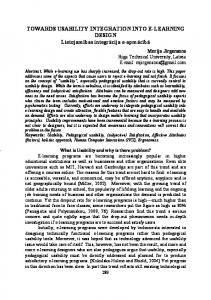
construction industry [Sanvido and Medeiros 1990]. The UK cladding sector mirrors this fragmentation, with the result that it is inefficient and lacks the capacity to compete effectively in the growing global market. Some of the key problems faced by the sector include: lack of integration of information on client needs, design, manufacture and installation, resulting in much rework, loss of data, and data generated at one stage not readily available for reuse downstream or on future projects; lack of standardisation in product description resulting in information and data exchange problems; and lack of co-ordination and collaboration between the different participants (clients, designers, systems suppliers, specialist sub-contractors (i.e. fabricators), installers, main contractors, etc.) involved in cladding projects. This situation, coupled with the need to improve the delivery process of cladding projects, led to the Computer- Integrated Manufacture of Cladding Systems (CIMclad) project [CIMclad 2000], an industry-led initiative investigating the feasibility of improving the efficiency and competitiveness of the cladding sector through the development of a standardisation and integration framework for computer-integrated manufacture of cladding systems for building projects. The initial focus is on rainscreen cladding [CWCT 1998, Anderson and Gill 1998], which serves as a pilot for the wider cladding sector. Rainscreen cladding is defined as a layered cladding system comprising of: • A visible outer skin that also forms the primary rain barrier. This causes the majority of water to drain down its surfaces, but does not prevent the passage of air into the air gap. • An air gap that prevents water ingress into the building. This provides ventilation and, depending on the design and dimensions of the rainscreen and air gap, may be intended to provide pressure equalisation across the outer skin. • A backing wall that forms an effective air barrier. This typically also provides support to the outer skin, and frequently includes an insulating layer. Figure 1 shows the key features of a rainscreen cladding. This paper describes current work on computer-based integration of the cladding project delivery process using a product model approach to improve information transfer. It first describes a generic cladding project delivery process, and analyses the rainscreen cladding sector to identify potential for process improvement within a standardisation, integration and automation framework. It then introduces the modelling approach adopted, and describes the scope of the initial rainscreen cladding product model being developed and the software implementation strategy.
Figure 1. Simplified illustration of rainscreen cladding [CWCT 1998] 438
Computing in Civil Engineering. ASCE Specialty Conference on Fully Integrated and Automated Project Processes. Eds. A D Songer & P Chinowsky Sept. 2001, pp 437-447
2.0 CLADDING SUPPLY CHAIN 2.1 CLADDING PROJECT DELIVERY PROCESS The design, fabrication and installation of cladding for a building project involves a supply chain comprising a number of participants having formal or informal relationships. The relationships between the different parties vary with the procurement method and their implications on the cladding process have been discussed in a CIMclad project report [Agbasi et. al. 2001]. Also described in the same report are the organisations forming the cladding supply chain and their roles. Generally, the project designer/specifier acting on the client’s brief, particularly within the boundaries of cost and performance, produces concept scheme drawings showing an outline of the elevations and sections of the building envelope. This process takes due consideration of the function of the envelope and visual effects through the selection of appropriate materials and performance specification. The concept scheme design is then taken through the planning approval stage and sufficient design detail is added to enable the building envelope work package to be put out to tender (except in a partnering scenario). Thus, the full scheme design produces general arrangement drawings of the building showing the elevation and section details of the building envelope, and specifications. The external appearance of the building envelope gives an indication of the type of cladding required. The general arrangement drawings and specification of the building envelope produced by the project design team form the basis for the detailed design of the cladding element. A cladding system is a component-based assembly usually involving a number of components. The detailed design produces a layout of the cladding including a schedule of component length and sizes, spacing of members, fixings and connections, and interfaces with other elements of the building. The design is aimed at satisfying the requirements of the project specifications but within the limits of the type of cladding system used. Using the materials bought in from the various suppliers, fabrication essentially involves cutting, drilling and punching the components to the required sizes and shapes, and packaging in readiness for site delivery. Installation is a site-based activity that involves the erection of the cladding components, in some instances pre-assembled, to complete the façade. 2.2 RAINSCREEN CLADDING SECTOR ANALYSIS The rainscreen cladding supply chain was chosen for the initial study, as it is perceived as a potential growth market. Analysis of information obtained from visits to a number of companies involved in the front-end through to the back-end activities of the supply chain revealed a growing pressure on project designers/specifiers from rainscreen cladding specialist contractors to improve the clarity of information on rainscreen cladding. The apparent lack of standardisation in product description has often led to poor communication of design intent leading to unwarranted design changes, increase in design time and cost, and inadequate pre and post-design specifications. Further down the supply chain, the specialist cladding contractors are reliant on design software tools provided by their system suppliers for the detailed design of rainscreen cladding. However, the communication of the rainscreen cladding full scheme design data by the project designers/specifiers is done via paper documents (i.e. drawings) in spite of the design data being produced in a digital format. This is attributed to the absence of effective data exchange capabilities between applications resulting in information needing to be re-entered. While Information and Communication
439
Computing in Civil Engineering. ASCE Specialty Conference on Fully Integrated and Automated Project Processes. Eds. A D Songer & P Chinowsky Sept. 2001, pp 437-447
Technologies (ICT) are now quite heavily used in the design of buildings, their use in the rainscreen cladding supply chain is currently limited. Efforts are being made by most organisations involved in the supply chain to improve their ICT usage. Regrettably, these individual efforts are hampered by the lack of an overall strategy within the sector for electronic information exchange across the supply chain. Currently, the cladding sector as a whole is not well placed to take full advantage of digital information. A major barrier is the fact that the sector is too small to support specialist CAD vendors, particularly at the design stage, with the result that much usage is relatively simplistic. To some extent this can be seen as an advantage as it presents an opportunity to bypass some of the less advantageous deployment stages and move the sector directly to leading edge ICT usage. The study also identified poor collaboration between participants involved in the scheme design of a project and the subsequent detailed design and supply of the rainscreen cladding. Current practice does not give adequate attention to the cladding work package at scheme design stage prior to letting the cladding contract, thus it is often not properly integrated into the whole building project. This is exemplified by the fact that cladding consultants or contractors are rarely included in the client’s design team to design or advise on the construction and performance of the building envelope at the scheme design stage. This procedure has been partly responsible for major revisions to the scheme design during the detailed design stage, and often has serious cost implications. The exception is where the cladding is complex and customised, or in a partnering arrangement, where the cladding contractor is appointed early in the procurement process to make an input to the work of the design team during, or immediately after, the scheme design stage. Clearly, there is greater scope for achieving optimal solutions with greater involvement of cladding consultants / contractors at the early stages of design. 2.3
FUTURE VISION
In relation to process integration, the construction industry lags behind the manufacturing industry in the adoption and implementation of ICT required to support an integrated working environment. This could be partly attributed to the product-oriented nature of the manufacturing industry making it more amenable to process integration and automation relative to the currently fragmented and project-driven construction industry. In the late 1980s, Yates [1987] recognised automation through integration as the major opportunity for improvement in construction productivity. The long-term vision for the whole of the cladding sector is the integration of all the stages of the cladding project delivery process. This is increasingly being recognised as vital for success in today’s competitive climate. Computer-integrated manufacture of cladding systems for building projects is still an aspiration for the cladding sector. This would involve a process where the scheme design of the cladding is transmitted digitally to the organisation responsible for the detailed design, and the subsequent fabrication of the cladding components is controlled without the need for paper documents. Today, different software vendors have addressed individual tasks leading to ‘islands of automation’ that are not integrated. From a software perspective, to achieve the vision of a fully integrated and largely automated cladding project processes, a single software suite spanning the whole specification-design-manufacture-installation cycle is needed. However, given the wide spectrum of activities that would need to be supported (for example drafting, detailing,
440
Computing in Civil Engineering. ASCE Specialty Conference on Fully Integrated and Automated Project Processes. Eds. A D Songer & P Chinowsky Sept. 2001, pp 437-447
estimating, costing, planning, scheduling, CNC control), a more realistic approach is to facilitate the effective flow of information between discrete applications. 3.0 INTEGRATION OF THE CLADDING PROJECT DELIVERY PROCESS 3.1
APPROACH
Section 2.2 highlighted some of the key problems facing the rainscreen cladding sector. Organisations involved in the cladding supply chain span two industries with different operating cultures. Therefore, an organisationally driven integration appears to be an unrealistic option since it requires the capture of knowledge across organizational boundaries, which may not be beneficial to smaller organisations. Instead, a common computer-based information architecture for sharing information between the organisations involved in cladding projects looks more promising. Judging from the rainscreen cladding sector analysis given in Section 2.2, the first step towards achieving a fully integrated and automated cladding project process would be to standardise the information interface between the scheme design and the detailed design. A product model that encapsulates the designer’s requirements has been proposed in the CIMclad project. The product model concept is introduced in the following section. It is envisaged that, amongst others, using a product model approach to improve information transfer should reduce the current design loop or changes in the design associated with missing or insufficient information in the scheme design and/or specification. Consequently, current work focuses on developing product model-based prototype design software that would capture and transfer information. 3.2 PRODUCT MODEL CONCEPT A product model is a coherent agreed model of the information that arises during the engineering design and the engineering realisation of a particular class of product [Watson 1995]. Its use is in the formal specification of data exchange standards for the efficient movement of information (in digital form) within the product supply-chain, between different applications software and between different companies. Almost all work on product models has either taken place within ISO 10303 [ISO 10303 1993], more commonly known as STEP (Standardisation for the Exchange of Product model data), or is based on parts of the ISO 10303 standard. The key feature of a product model is that it defines how the underlying engineering information should be structured (conceptual schema) rather than focusing on a graphical representation thus overcoming the limitations associated with the first generation graphical CAD data exchange standards such as the Initial Graphic Exchange Specification (IGES), a specification for exchange of geometry between systems. The shortcomings of IGES in transferring non-geometric product design information have been reported elsewhere [Wilson 1987]. The central object classes of product models describe the functional parts of the artefact and assemblies formed by them, rather than the concepts needed for representing them in different kinds of documents. At present, there are two product model based data exchange standards that will have a major impact on the future usage of ICT within the construction sector, the International Alliance for Interoperability (IAI)’s Industry Foundation Classes (IFC) [IAI 1996] and CIMsteel Integration Standard (CIS) [Crowley et. al. 1995]. Both are based on established product model concepts outlined in STEP and they represent a strategic approach based on mapping
441
Computing in Civil Engineering. ASCE Specialty Conference on Fully Integrated and Automated Project Processes. Eds. A D Songer & P Chinowsky Sept. 2001, pp 437-447
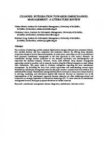
engineering information into agreed coherent neutral representations. Whilst IFC aims at bringing about interoperability within the construction sector, with particular emphasis on cross-disciplinary co-ordination and sharing information down the full project life-cycle, the CIS focuses on the steel sector and provide comprehensive data exchange standards for structural steel frames spanning analysis and design, detailing, fabrication and erection. A significant number of construction-related product modelling research has taken place. This has resulted in a number of all-encompassing product models, such as the RATAS model [Bjork 1989], GARM model [Gielingh 1988] and the AEC Building Systems model [Turner 1990], being proposed. However, many of the building product models that have been proposed in the literature are rather theoretical and yet to reach a stage where they can easily be implemented by software companies [Karhu 1997]. There has been a shift from allencompassing product models to conceptual schemas describing more limited domains, also described as aspect models. An example of an aspect models is the Integrated Data Model (IDM) provided by the COMBINE project [Dubois et. al. 1992]. Karhu [1997] has implemented product model-based prototype software for design of precast façades. 3.3 PROCESS INTEGRATION The first steps in the development of the product model are to understand and define the process within which the data exchange has to take place and develop a conceptual schema defining the information requirements of the product model. This is a prerequisite for integration and automation of any process. Case studies of companies involved in the rainscreen supply chain were undertaken to establish the current industry practice as described in Section 2.1. The companies included those engaged in the front-end activities – project designers/specifiers and those involved in back-end activities – rainscreen cladding contractors which include system fabricators and installers. Existing models such as the Generic Design and Construction Process Protocol [Kagioglou et. al. 1998] and the Architect’s Plan of Work [RIBA 2000] provide high-level information on processes involved in construction and building projects respectively. No formal model currently addresses the procurement and installation of rainscreen cladding, a subset of a building supply chain. Although the processes involved are understood within the cladding supply chain, they need to be made explicit to the wider building industry. The business processes of the supply chain can be broadly split into five stages: scheme design (concept and full scheme design), rainscreen contract, installation design (detailed design), rainscreen fabrication, and rainscreen installation. To model the process, IDEF0 [IDEF0 1993] derived from the structured analysis and design technique [Marca and McGowan 1987] was chosen as the activity-modelling tool. A formal IDEF0 process model [Kalian et. al. 2001a] spanning the total process from developing a cladding system through developing the design of a particular rainscreen installation to fabricating and installing the rainscreen has been developed. A simplified version of the model focusing only on the five stages is shown in Figure 2. The model defines the incremental aggregation and transfer of information down the design-to-install supply chain. It is an idealised process model that employs a simple linear sequence of logical stages. Each stage represents a coherent collection of activities that, on the procurement of a particular rainscreen, may or may not follow the temporal order implied by this simplified model.
442
Computing in Civil Engineering. ASCE Specialty Conference on Fully Integrated and Automated Project Processes. Eds. A D Songer & P Chinowsky Sept. 2001, pp 437-447 The tender (or other) process by which the rainscreen contractor is appointed and the contractual framework established. Including the specifications for the rainscreen.
Development of the full scheme design for the project as-awhole. Within which the outline scheme design for the rainscreen is established.
Development of the coordinated design and production information for the rainscreen. Including establishing the parameters governing its installation.
Manufacture and pre assembly Fabrication of the rainscreen components and their timely delivery to site. Including developing the installation method statement.
The installation and commissioning of the rainscreen. Including any as-built documentation
Rainscreen Contract
Design the Installation
Scheme Design
Full scheme design for overall project Outline scheme design for rainscreen
Contract document Rainscreen specification Programme milestones
Full design Installation sequence
Fabricate Rainscreen
Fabrication drawings Delivery schedule Installation method statement Inspection certificates
Install Rainscreen
Co-ordinated installation programme. Installation progress record As-built document Commissioning report Completion Certificate
Focus of PM
Figure 2. Simplified process model for rainscreen cladding The initial focus of the product model is the interface between scheme and detailed design as shown in Figure 2. A complementary information technology-based process model for the cladding sector is presented in Figure 3. This figure shows both the current technology, which is largely 2D (i.e. two dimensional) CAD, and the projected technology which anticipates the wider building design process migrating to 3D CAD and onward to more formal building models. On these diagrams the initial scope of the rainscreen product model is shown dotted. The role of this product model is to capture the requirements against which the rainscreen scheme design was developed, and to transfer all this information into the full design stage. As relatively little information needs to be captured about the third dimension, this initial product model has been called the “2D PM”. Thus the 2D PM holds information relating to each rainscreen elevation, enabling this information to “painted” onto the building model that exists at full design stage. This does mean that industrial deployment of the 2D PM can take place prior to 3D CAD being widely adopted, but additional advantages will result when using 3D CAD.
443
Computing in Civil Engineering. ASCE Specialty Conference on Fully Integrated and Automated Project Processes. Eds. A D Songer & P Chinowsky Sept. 2001, pp 437-447 2D CAD
2D CAD
3D CAD
3D CAD
Building Scheme Design
Building Full Design
Building Scheme Design
Building Full Design
Concept Scheme generic
Specifications outline
Specifications full
Specifications outline
2D CAD
Marked-up 2D CAD
Full or vendors Design specific
Fabrication Drawings specific
Specifications full
Full 2D+ PM Design specific
Concept 2D PM Scheme generic
2D CAD or vendors
Specifications generic
Specifications “generic”
Specifications generic
Specifications specific
Specifications “generic”
Specifications specific
Fabrication Drawings specific 2D+ CAD or vendors
Projected Technology
Current Technology
Figure 3. Scope of the initial rainscreen product model (2D PM) The projected technology diagram also shows a 2D+ PM. This extended product model will have the additional capability of capturing the full rainscreen design, and will convey this spatially more detailed information into fabrication and installation, thus integrate downstream activities. The 2D+ PM could be imported into 3D design and detailing applications to provide back-end drivers for computer numerically controlled (CNC) cutting, sawing and drilling lines. This is outside the scope of the current work but would be the focus of future development work. In defining the requirements for the product model(s), the focus was on the underlying information irrespective of the contractual framework or procurement route (since these are variable and could easily change in the future). Figure 4 indicates the graphical relationships between entities on initial 2D PM for rainscreen cladding. Each entity, graphically represented by a box, holds a cluster of information that defines its characteristics and the relationships with other entities are shown with the connecting lines. The 2D PM is restricted in scope to capturing the rainscreen cladding to a particular elevation of a building (where all the cladding lies parallel to a specified reference gridline). Thus, the model is to be used for each elevation of the building but generalisation to capture each elevation within a single model would not be difficult. Capturing requirements relating to curved rainscreen cladding lies beyond the scope of the 2D model. Entities on the upper left hand side of Figure 4: building, building footprint, and context are important for positioning rainscreen cladding-related data within the overall building. The building entity defines the characteristics of the building as a whole, for example location, site elevation, building height, local environment, and it has a footprint which is the plan shape of the building, and a rainscreen cladding element which captures the general requirements of the rainscreen cladding such as budget, design data and specification. For each elevation of the building with rainscreen cladding, the rainscreen extent, boundary conditions, openings, visual and external features characterises the rainscreen. The rainscreen area represents an area with a similar type of rainscreen and performance requirement within a contiguous area of rainscreen as defined by the rainscreen extent. Also for each elevation of the building, its context entity holds location-related information on adjacent building parts such as the reference grid for the rainscreen, adjacent building grids and finished floor levels, and supporting structure to the rainscreen elevation. The support structure consists of the structural interface and the backing wall, relating to the potential lines of support along the structural interface (beam, slab, column), and area of the backing wall (ignoring any openings) to an elevation respectively. The type definitions of the entities are also shown in Figure 4 and a more formal presentation of the entities and their attributes have been reported in detail elsewhere [Kalian et. al. 2001b].
444
Computing in Civil Engineering. ASCE Specialty Conference on Fully Integrated and Automated Project Processes. Eds. A D Songer & P Chinowsky Sept. 2001, pp 437-447
Building Footprint Building
RainscreenCladding
Context
Elevation
Type of Rainscreen Cladding
Type of Structural Edge
RainscreenArea
Boundary Condition
Type of Rainscreen Performance
Type of Boundary Condition
Structure
Structural Interface
RainscreenExtent
Opening
Backing Wall
Type of Opening
Type of Backing Wall
Visual Feature External Feature
Type of External Feature
Type of Visual Feature
Figure 4. Indicative rainscreen cladding 2D PM 4.0
2D PM PROTOTYPE SOFTWARE
Incremental implementation and experimentation of prototype software both to test and prove the 2D PM product model is currently in progress. The implementation architecture envisages two applications; input (Specifier) and output (Browser) tools at the concept scheme design stage, to facilitate the development of the requirements, and a similar browser application to convey these to the full scheme design stage. One of the practical constraints in using a product model to “export” information from one application and “import” that information into another is that it requires considerable programming effort to create the necessary data exchange “translators”. The strategy adopted is to side-step this problem by exploiting existing data exchange “translators”, specifically the Industry Foundation Classes (IFC) translators that are provided with some CAD systems such as Autodesk’s Architectural Desktop and GraphiSoft’s ArchiCAD. This is appropriate because the initial 2D PM links the scheme design to the detailed design which are more in the front-end construction industry domain rather than the back-end manufacturing industry domain of the project delivery process. A property-set based approach has been adopted which will be more fully reported in a future paper. 5.0 CONCLUSION This paper has described on-going project aimed at integrating and standardising the information flow in a rainscreen cladding project using a product model. This is a prerequisite for full automation of the project delivery process. Review of the current industry practice identified bottlenecks that informed the focus of the initial product model – 445
Computing in Civil Engineering. ASCE Specialty Conference on Fully Integrated and Automated Project Processes. Eds. A D Songer & P Chinowsky Sept. 2001, pp 437-447
to bridge the scheme and detail design. The current procurement process has been modelled and the scope of the initial 2D PM is defined. Work is in progress to implement the 2D PM prototype software tool, a design phase tool that would capture and transmit the requirements for rainscreen cladding. This is intended to lead, in the longer term, to full scale computerintegrated manufacture of cladding systems. Acknowlegement The CIMclad project is funded under the Innovative Manufacturing Initiative: Meeting Clients’ Needs Through Standardisation (EPSRC/DETR LINK project GR/N12770). In addition to the two academic partners, the project involves a significant number of industrial partners whose input to this paper is gratefully acknowledged as are input from other sources. For more details visit the project web site: http://www.cae.civil.leeds.ac.uk/current/cimclad 6.0 REFERENCES Agbasi E, Anumba C, Gibb A, Kalian A and Watson A (2001) Potential for process improvement. Computer integrated manufacture of cladding systems (CIMclad) Report 1. ISBN 1-897911-18-1, 59 pp Anderson J M and Gill J R (1998) Rainscreen cladding: a guide to design principles and practice. CIRIA Building and Structural Design Report: Walls, Construction Industry Research and Information Association, Butterworths, 98 pp Björk B-C (1989) Basic structure of a proposed Building Product Model. Computer Aided Design, Vol. 21, No. 2, pp 71-78 CIB (1997) The State of the Construction Industry. Construction Industry Board, Issue 7, February CIMclad (2000) Computer Integrated Manufacture of Cladding Systems. EPSRC/DETR LINK project GR/N12770, IMI MCNS http://www.cae.civil.leeds.ac.uk/current/cimclad Construct IT (1995) An Information Technology Strategy for the United Kingdom Construction Industry. BT/Department of the Environment, HMSO, London Crowley A, Watson A S, Knowles G M et al. (1995) CIMsteel Integration Standards Part 8, Data Exchange Protocols. The CIMsteel Project, London September, 500 pp CWCT (1998) Standard for Walls with Ventilated Rainscreens. Centre for Window and Cladding Technology, July, 56 pp DETR (1998) Rethinking Construction. The Sir John Egan Task Force Report, Department of the Environment, Transport and the Regions, London, July Dubois A M, Escudié J C and Laret L (1992). COMBINE Integrated Data Model. Vol. I – NIAM diagram, Vol. II – Dictionary, V.3.3, 920123, CSTB, Sophia Antipolis, France Gielingh W (1988)] General Architecture Engineering and Construction Reference Model. ISO TC 184/SC4/WG1 Doc. 3.2.2.1, TNO Building and Construction Research, BI-88-150, Delf IAI (1996) International Alliance for Interoperability http://iaiweb.lbl.gov/ IDEF0 (1993) Integration Definition for Function Modelling. Draft Federal Information Processing Standards Publications (FIPS PUBS) 183, December, 80 pp ISO 10303 (1993) Standard for the Exchange of Product Data (STEP). International standard for the computer-interpretable representation and exchange of product data. International Standard Organisation, Geneva, Switzerland
446
Computing in Civil Engineering. ASCE Specialty Conference on Fully Integrated and Automated Project Processes. Eds. A D Songer & P Chinowsky Sept. 2001, pp 437-447
Kagioglou M, Cooper R, Aouad G, Hinks J, Sexton M, Sheath D (1998) Generic Design and Construction Process Protocol. Final Report, The University of Salford, ISBN 090 289 619 9, 178 pp Kalian A, Watson A, Agbasi E, Anumba C, Gibb A (2001a) Information and Communication Technologies (ICT) Usage: Current and Future. Computer integrated manufacture of cladding systems (CIMclad) Report 2, ISBN 0-904280-02-0, 45 pp Kalian A, Watson A, Agbasi E, Anumba C, Gibb A (2001b) Draft – 2D PM Requiremenst Specification. Computer integrated manufacture of cladding systems (CIMclad), 9 pp Karhu V (1997) Product model based design of precast façades. Electronic Journal of Information Technology in Construction, ITcon, Ed. B-C Björk, Vol. 2, pp 1-31, http://itcon.org Marca D A and McGowan C L (1987) SADT- Structured analysis and design technique. McGraw-Hill, New York RIBA (2000) The Architect’s Plan of Work. Royal Institution of British Architects (RIBA) Publication, ISBN 1 859460682 Sanvido V E and Medeiros D J (1990) Applying Computer-Integrated Manufacturing Concepts to Construction. ASCE Journal of Construction Engineering and Management, Vol. 116, No. 2, p 365-379 Turner J (1990) AEC Building Systems Model. ISO TC184/SC4/WG1, Working Paper, Doc. No. 363 Watson A (1995) Product models and beyond. Integrated Construction Information, Eds. P. Brandon and M Betts M, E&FN Spon, London, ISBN 0 419 203702, p 159-172 Wilson P (1987) Graphic Standards, IEEE Computer Graphics and Applications, Vol. 7, No. 11, p 58-61 Yates A P (1987) Changes in the construction sector resulting from technology advances. Cited in Sanvido V E and Medeiros D J (1990)
447