MATEC Web of Conferences 112, 06004 (2017)
DOI: 10.1051/ matecconf/201711206004
IManE&E 2017
5-axes modular CNC machining center Radu-Eugen Breaz*, Sever-Gabriel Racz, and Octavian-Constantin Bologa 1 Lucian Blaga, University of Sibiu, Department of Industrial Machines and Equipment, Emil Cioran 4, Sibiu, Romania
Abstract. The paper presents the development of a 5-axes CNC machining center. The main goal of the machine was to provide the students a practical layout for training in advanced CAM techniques. The mechanical structure of the machine was built in a modular way by a specialized company, which also implemented the CNC controller. The authors of this paper developed the geometric and kinematic model of the CNC machining center and the post-processor, in order to use the machine in a CAM environment.
1 Introduction CNC machine-tools represent the backbone of nowadays machine-building industry. Consequently, using and programming CNC machine-tools are important subjects within the curriculum in technical universities. While 3-axes CNC machine-tools are widely used in industry, currently we are witnessing the introduction of 5-axes CNC machine-tools in more and more industry sectors. In order to offer the students state of the art training with regards of CNC machinetools, universities have to equip their laboratories with both 3-axes and 5-axes machine tools. While industrial 5-axes CNC machine-tools may be a rational choice where complex and highly accurate parts are required, for teaching purposes, this king of equipment may be too expensive. So, the problem tackled by this research work was to develop a 5-axes machining center, with similar technological capabilities as industrial state of the art solutions, at an affordable level of development costs and suitable to be used for teaching the future engineers how to use and program 5-axes CNC machine-tools. 1.1 Open architecture CNC machine-tools Industrial CNC machine-tools are supplied as closed architecture systems. Their structure, kinematic and CNC controllers are designed to be used solely for their basic purpose, without any possibility to change it. Practically these systems have no re-configurability and cannot be adapted in order to perform other machining processes other the one they were designed for. The re-configurability is seen here as the ability to add or remove modules from the machine, to equip it with supplementary degrees of freedom (axes). Their CNC controllers have also closed architecture which cannot be modified. *
Corresponding author:
[email protected]
© The Authors, published by EDP Sciences. This is an open access article distributed under the terms of the Creative Commons Attribution License 4.0 (http://creativecommons.org/licenses/by/4.0/).
MATEC Web of Conferences 112, 06004 (2017)
DOI: 10.1051/ matecconf/201711206004
IManE&E 2017 As opposite to the closed architecture, researches were reported in the literature of open systems CNC architecture [1-2]. One of the most known approaches of developing such systems are OSACA (Europe), OMAC (USA) and OMEC (Japan) [3]. These systems are based on building a CNC system form modular components and standardized interfaces. Other approaches of developing open architecture CNC systems are relying on the STEP NC concept, which tries to develop a machine independent programming language [4].
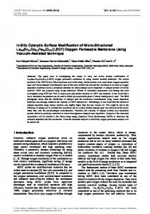
2 The structure of the 5-axes CNC machining center The workspace of CNC machine-tools is defined as a Cartesian one, with three translational axes (X, Y, and Z) and three rotational axes (A, B, C), as presented in Figure 1.
Fig. 1. The Cartesian workspace used for CNC machine-tools.
A large amount of the CNC machine-tools on the market can only perform translational movements on X, Y and Z axes and are called 3-axes CNC machine-tools. In order to machine complex parts sometime one or even two supplementary rotational movements in combination with translation along X, Y and Z axes are required. In order to perform such motions 5-axes CNC machine-tools are used. A simplified diagram of a 5-axes CNC machine-tool, with X, Y, Z translational axes and A, C rotational axes is presented in Figure 2.
Fig. 2. Simplified diagram of a 5-axes CNC machine-tool with X, Y, Z, A and C kinematic.
In order to develop the 5-axes modular machining center, a requirements list regarding the machine’s characteristics was build. The list is presented below: - the kinematic if the machine has to allow simultaneous movements on 5-axes; - the machine has to be built in a modular way, in order to allow its use both as 3axes and 5-axes machine-tool; - the machine has to be programmed using G-code (formalized as ISO 6983); - the control loops on each axis has to be closed loop ones (using servomotors for actuation and encoders for feedback – no stepping motors were allowed); - the overall developing costs of the system must not exceed 25.000 Euro.
2
MATEC Web of Conferences 112, 06004 (2017)
DOI: 10.1051/ matecconf/201711206004
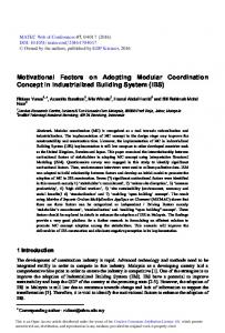
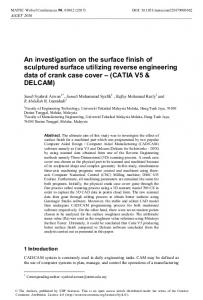
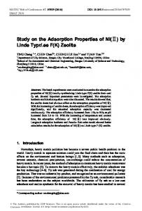
IManE&E 2017 2.1 Mechanical structure The machine structure was designed modularly, by combining the following modules: A. Custom built modules: - mechanical frame; fixed table; movable portal unit for X-axis; movable slide for Y-axis; movable slide with Z-axis. B. Special units from ISEL company: - rotary tilting unit DSH-S combined with rotary unit RDH-S; - spindle motor unit iSA 1500 (with manual tool exchange). The overall view of the 5-axes CNC machining center is presented in Figure 3.
Fig. 3. Overall view of the 5-axes machining center.
The custom-built modules also include in their structure specific ISEL components such as linear guideways and linear slides. The general assembly of the machining center was made by company General Numeric, from Brașov, Romania, a company specialized in manufacturing CNC profiling machines (oxy-gas and/or plasma cutting) and CNC routers.
b
a
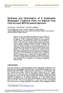
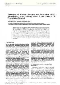
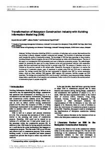
Fig. 4. Rotational axes A and C (a – real view, b – schematics of DSH-S module [5])
Figure 4 a, b shows the combined modules DSH-S (tilting) and RDH-S (rotary) which embodies the rotational axes A and C respectively. The combined modules are based upon the ISEL harmonic drive and allow the rotational movements around the swivel axis (A) and the rotary axis (C) presented in Figure 4 b [5].
3
MATEC Web of Conferences 112, 06004 (2017)
DOI: 10.1051/ matecconf/201711206004
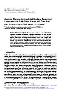
IManE&E 2017 In Figure 4 b, 1 represents the counter bearing, 2 the swivel unit and 3 the rotary indexing table RDH-S. 2.2 The CNC controller In order to provide open-architecture capabilities to the machining center the LinuxCNC software system was used as CNC controller. It can drive milling machines, lathes, 3D printers, laser cutters, plasma cutters, robot arms, hexapods, and more. LinuxCNC is also compatible with many popular machine control hardware interfaces and provides to the user several graphical user interfaces [6]. The integration of LinuxCNC as controller of the 5-axes machining center was also made by General Numeric company. The GUI used for this machine-tool is presented in Figure 5.
Fig. 5. Graphical user interface (GUI) of LinuxCNC controller.
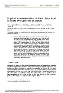
3 The geometric and kinematic model 5-axes machining operations rises a series of problems which do not appear during normal 3-axes machining. While during 3-axes machining only reciprocal movements between tool and workpiece occur and have to be taken into consideration for collisions avoidance, things are very different for 5-axes machining. The number of movements are higher, because of the supplementary rotational movements, and collisions may occur not only between tool and workpiece but also between tool, workpiece and machine slides and platters and between machine slides and platters themselves. The simulation interface from Linux CNC is only able the represent the toolpaths, without taking into consideration the workpiece and machine geometry and the potential collisions. Moreover, most of CAM software packages do not take into consideration the geometry and kinematics of the machine when simulating the machining process. To address this problem, the authors of this work have developed a geometric and kinematic model of the 5-axes machining center, by performing the following steps [7]: - building a 3D model of the machine-tool; This step was performed by a joint modelling and import process. While the custom build modules of the machine were modeled, the 3D models of specialized ISEL modules were imported form the files provided by the manufacturer. Figure 6 shows the 3D model of the machining center, developed in CATIA. - separating each kinematic axis of the machine form the 3D model and saving it as an individual module; During these two first steps, some alterations of the geometry of the components are allowed in order to reduce the size of the files. The user has to keep in mind that only the components which may lead to collision are important, while inside components, or components which cannot interfere with others components may be simplified or even removed. For example, from Figure 6 it can be noticed that the height of the machine has been reduced, because the machine supports cannot collide with any moving parts.
4
MATEC Web of Conferences 112, 06004 (2017)
DOI: 10.1051/ matecconf/201711206004
IManE&E 2017
Fig. 6. The 3D model of the machine in CATIA.
- exporting the axis modules as igs file and re-importing them in a CAM software package; - using a specialized module of the CAM software to build the kinematic model of the machine; During this final step, the user has to define the hierarchies between each axis (for example, axis X supports both axes Y and Z, axis Y supports axis Z) and the kinematic dependencies between the axes (for example, axis X cannot be moved without moving also axes Y and Z). Also, the stroke length (and angular limits) for each axis have to be defined. After building the geometric and kinematic model, the CAM software was able to realistically simulate the machining processes unfolded on the machine. Figure 7 presents a screenshot form a simulation of a 3+2 axes indexed milling process (the rotational movements involved in the process are indexing movements, performed outside the milling process, used only for positioning the part).
Fig. 7. Screenshot form a 3+2 axes indexed milling process simulation.
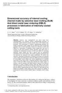
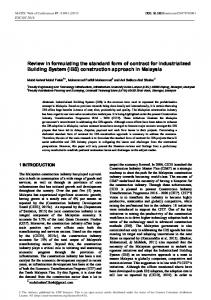
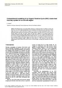
Figure 8 a, b presents screenshots form a simulation of a 5 axes continuous milling process. During this machining process simultaneous movements occur on all five axes of the machine.
4 Conclusion During this research program, a modular 5-axes machining center was developed and implemented. The machine was built by a specialized industrial company according to a requirements list made by the authors of this work. In order to be able to use the machine
5
MATEC Web of Conferences 112, 06004 (2017)
DOI: 10.1051/ matecconf/201711206004
IManE&E 2017 in a CAM environment, a geometric and kinematic model of the machine was built, which allow the user to realistically simulate the machining process.
a
b
Fig. 8. Screenshots form a 5 axes continuous milling process simulation.
By using the geometric and kinematic model, the CAM program is able to generate the complex toolpaths required for 5-axes machining operations, by taking into consideration the real kinematic capabilities of the machine (hierarchies and dependencies between machine axis). Also, the simulation process is able to detect not only tool-workpiece collisions, but also the collisions between the mobile elements of the machine. The authors want to thank the students from the second study year (now graduates of 2016) of “CAD/CAE/CAM Techniques in Plastic Deformation” Master study programme from “Lucian Blaga” University of Sibiu, which built the 3D assembly model of the 5-axes machining center. Special thanks are also owed to Eng. Meszaros Mihai Dan, graduate of the above mentioned Master programme, which assisted the authors in the process of developing the kinematic and geometric model of the machining center.
References 1. 2. 3. 4. 5. 6. 7.
H. Tianliang, Z. Chengrui, L. Riliang, L. Peng, Int. J. Adv. Manuf. Technol., 40(5), 541–552, (2009) S. Park, S.-H. Kim, H. Cho, Int. J. Adv. Manuf. Technol., 27, 788-796, (2006) W. Sperling, P. Lutz, Robot Manuf., 6, 613–620, (1996) C. Zhang, R. Liu, T. Hu, Int. J. Comput. Integr. Manuf., 19(6), 508–515, (2006) *** https://www.isel.com/en/downloads/dl/file/id/4268/assembly_instruction_rdh_dsh.pdf *** http://www.linuxcnc.org/ A. L. Chicea, R. E. Breaz, O. Bologa, Applied Mechanics and Materials, 809-810, 1004-1009, (2015)
6