P Impulse switch mode without time function (only types with option P). PN
Impulse .... applying the supply voltage U, if the output relay R was in on-position.
Red And Orange Wire Positive (+). Black And Brown Wire Negative(-). * Weight ... Noise is measured in anechoic chamber i
solutions with an in-depth knowledge of local market conditions. GE's service ... Microsoft. Linux. Apple. Unix. LAN Swi
Siemens Building Technologies, Inc. Page 1 of 5. PXC Modular Series. Figure 1.
... Modular) is an integral part of the APOGEE®. Automation System. It is a high ...
Series UPS a perfect choice for environmental-friendly solutions. .... Whether you are a large corporation with multiple
internal transformer protection: Thermostat / Buchholz (ANSI 26/63) ......
Protection of pumps against the consequences of a loss of priming by the
detection.
biomedical, agriculture, safety, electrical and electronics industries. The topics describe the .... With this function, we know that the water level linearly equivalent with the ...... equipment such as switchgear and other power grid application.
Sepam series 20. Sepam series 40. Sepam series 80. Electrical network
protection. Catalogue. 2005. SEPED303005EN_cover.fm Page 1 Mardi, 17. mai
2005 ...
43711 Partlow Rd ⢠Ashburn, VA 20147. 571-252-2111 ⢠703-771-6631 (fax) www.lcps.org /at. Tools for Success. Assisti
In Europe: 31 20 547 2111. ⢠In Japan: 0120â421â345. Or use our Web link for information on contacting Keysight wo
Periodically, Keysight releases software updates to fix known defects and incorpo- rate product enhancements. To search
Timing Diagram: Contact Information: Solid state switching device 1 form A;
normally open series connection. Continuous current rating 2 amperes.
Maximum ...
means to master event-driven programming, because their requirements include
those .... This is not intended to be a comprehensive tutorial on NCurses.
Sepam series 20. Sepam series 40. Sepam series 80. Electrical network
protection. Catalogue. 2005. SEPED303005EN_cover.fm Page 1 Mardi, 17. mai
2005 ...
Each Fluke 20, 70, 80, 170 and 180 Series DMM will be free from defects in
material and ... charge for importation costs of repair/replacement parts if the
product ...
80 Series Standards and 180/181 Series Brackets offer the widest .... 200230-7
BLK ... 8". 180 ALM 8. 180 ANO 8. 180 BLK 8. 180 BR 8. 180 BN 8. 180 TI 8.
tonic features of the area; historical earthquakes occurred in the ... together. The history of seismic zones in. Italy follows the ... Oakland, California 94612 U.S.A..
mary surface rupture is along the Paganica fault, the geometry of which is .... Our geological surveys and analyses of aerial photographs taken after the ... The white stars indicate the ... free-faces) have been observed, respectively (left panel).
"really into." These interests might. Once some powerful bait has been include computer games, cooking, selected, use it to set the trap. No building model cars ...
The water tight system in the Girbau washers' bearings is guaranteed since it is ...
parts are highly accessible by simply removing the rear cover of the washer.
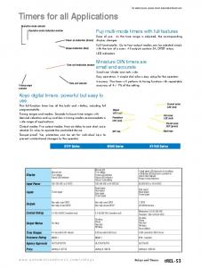
Relays and Timers. 1-800-633-0405 e27-54. Volume 14. Fuji multi-mode timers
with full features. Operation mode selector. Operation mode indication window.
AVR timers do a similar job, measuring a given time interval. An AVR timer in
simplest term is a register. Timers generally have a resolution of 8 or 16 bits. So
an.
Wiring diagram. (without control ... 1. Features. Multi-function and mono-function
timer range .... 80 Series - Modular Solid State timer (SST) 1 A. For outline ...
• 17.5 mm wide • Six time scales from 0.1 s to 24 h • High input/output isolation • 35 mm rail (EN 60715) mount • “Blade + cross” - both flat blade and cross head screw drivers can be used to adjust the range and function selectors, the timing trimmer, and to disengage the rail mounting clip • New multi-voltage versions with “PWM clever” technology 80.01 / 80.11 Screw terminal
• Multi-voltage • Multi-function
• Multi-voltage • Mono-function
AI: On-delay DI: Interval SW: Symmetrical flasher (starting pulse on) BE: Off-delay with control signal CE: On- and off-delay with control signal DE: Interval with control signal on
AI: On-delay
For UL ratings see: “General technical information” page V Wiring diagram (without control signal)