Sharma. 2012. Int. J. Vehicle Structures & Systems, 4(2), 52-63 ISSN: 0975-3060 (Print), 0975-3540 (Online) doi: 10.4273/ijvss.4.2.04 © 2012. MechAero Foundation for Technical Research & Education Excellence
Inter nati onal Jour nal of Vehicle Structures & Systems Available online at www.ijvss.maftree.org
Recent Advances in Railway Vehicle Dynamics Rakesh Chandmal Sharma Maharishi Markendeshwar University, Mullana (Ambala), India Email:
[email protected]
ABSTRACT: In this paper, the state of the art of railway vehicle dynamics is presented. Much of the attention is paid to the performance characteristics such as lateral stability, curving, multibody simulation, wheel to track interaction, ride quality and comfort. The scope and limitations of linear and nonlinear analyses for vehicle dynamics are reviewed. Two and three dimensional theories for wheel-to-track interaction are discussed. Detailed analysis of ride quality and comfort evaluation methods is presented. Some concluding remarks are discussed along with further directions of research in the railway vehicle dynamics. KEYWORDS: Railway vehicle dynamics; Performance indices; Lateral stability; Ride comfort; Creep forces. CITATION: R.C. Sharma. 2012. Recent Advances in Railway Vehicle Dynamics, Int. J. Vehicle Structures & Systems, 4(2), 52-63. doi:10.4273/ijvss.4.2.04 is sponsoring research projects across a broad spectrum of rail vehicle and track dynamics. It is also developing a High Speed Ground Test Centre at Pueblo, Colorado, which is providing one of the most advanced ground transportation facilities in the world. In the recent past research activities in railway vehicle dynamics problems have also been largely contributed by China and Sweden. In India, Research Designs and Standards Organisation, Lucknow is working towards the research and development in rail vehicle systems specific to the problems of Indian Railways.
NOMENCLATURE V
r a F(f) B f
Vehicle forward speed (m/s) Conicity or taper ratio (rad) Nominal rolling radius (m) One half of rail gauge (m) Frequency weighting factor Acceleration weighting factor Frequency (Hz)
1. Introduction Over the last twenty-five years, there has been an increasing effort devoted to railway vehicle research and development. Researchers have directed their efforts for achieving excellence in improving stability, curving guidance, ride comfort and other performance indices of railway vehicle dynamics. The research efforts in rail vehicle dynamics of the British Railways Research Center at Derby have been recognized around the world for their excellence in this area. The Railway Technical Research Institute of the Japanese National Railways has also led the way in railway vehicle dynamics research. In the European continent, the Office of Research & Experiments of the International Union of Railways has committees of experts in all the research areas of interest to the railways. These committees, including railway research and operating personnel and university researchers, identify and sponsor the research. The Canadian Pacific Railroads have done much research into railway vehicle dynamics problems. In the United States of America, the individual railroads and railroad suppliers have performed in-house research while the research centre of the Association of American Railroads at Chicago has served to focus attention on problems common to all industry. The Federal Railroad Administration of the U.S. Department of Transportation
2. Lateral Stability and Curving Guidance Stability problems are generally lumped under the broad term of ‘hunting.’ Primary hunting involves lateral, yaw, and rolling motions of the car body (with little bogie and wheel set motion). Secondary hunting is a coupled oscillation in yaw and lateral displacement of the wheelsets and bogie (with little car body motion) which is damped below a certain critical value of forward speed. Above the critical speed, disturbances of the bogie from equilibrium result in the track slamming from rail to rail with the motion limited by the wheel flanges. As hunting of wheelsets is qualitatively similar to that of complete bogie, investigations focussing on detailed aspects of bogie or wheel set hunting have frequently utilized the simplest model of a wheel set. The wheel set has been considered as two wheels rigidly connected by an axle, which most investigators have assumed to be isolated from the bogie through the primary suspension system. In past, investigators have examined the lateral stability by considering different wheel set models [86, 90 and 91]. Approximation for the critical speeds of hunting has been found from the stability analyses of the 52
Sharma et al. 2012. Int. J. Vehicle Structures & Systems, 4(2), 52-63
motion for a single wheel set is V ( / ar ) . When there is no primary suspension elements connecting the wheel set to the bogie, this oscillation is neutrally damped at very low speeds. When the wheel set is mounted in a bogie frame such that there are primary suspension elements between the wheel set and bogie frame and secondary suspension elements between bogie frame and car body, the coupled oscillation in yaw and lateral displacements will be damped at low speeds. However, as speed is increased above the critical speed, the disturbances of the wheel set or bogie from equilibrium will increase with time. It can be shown that the linear critical speed is proportional to 1 / . Some investigators use the secondary hunting mode by referring the coupled lateral and yaw oscillation. In order to achieve good guidance on straight track, the frequency of wheel set or bogie hunting mode should be high to facilitate a fast response of the selfcentring action [85]. On curved track, guidance should be achieved by the creep forces acting on the wheel treads rather than depending on the flange contact [87]. In the past, researchers have undergone a thorough analysis on curving without flange contact under the action of creep forces. They concluded that curving without flange contact is facilitated by flexible suspensions, large conicity or wheel taper ratio, and short wheelbase [86 and 87]. Unfortunately, these requirements conflict with the requirements for stability of the bogie-hunting mode. The creep forces required for guidance in curved track also cause serious reductions in the available adhesion for traction and braking. In designing of good guidance performance on tangent track and curves, it is desirable that the characteristics of components do not change materially with the length of service or changes in environmental conditions. Both the linear critical speed and the curving performance depend strongly on the wheel conicity and suspension flexibility. As wheels wear, the lateral profile gradually changes from a straight to a curved profile. The effective conicity usually increases during this process and the dynamic performance will deteriorate with the wheel wear. There is a trade-off between the curving performance and the lateral stability of a rail vehicle. Effective conicity at the wheel rail interface, suspension flexibility, rail vehicle design and track quality are the few parameters which decide curving performance and lateral stability of a rail vehicle. Compatibility between steering ability and lateral stability has been the area of interest for different researchers [64, 65, 67, 70, 74, 75, 79, 80 and 82]. It has been shown by researchers that for railway vehicles the stiffness and kinematic properties of all possible inter-wheel set connections are characterised by bending and shear stiffnesses. The analytical solution of the equations of motion for a simple mathematical representation of a railway bogie shows that the bending stiffness can be reduced whilst the shear stiffness is increased to maintain a constant critical speed. At this speed, the real part of the Eigen value representing the kinematic movements of the wheelsets becomes positive. With a conventional bogie, with each wheel set restrained both in lateral and yaw axes to the bogie frame, the maximum shear stiffness is directly
linear equations of motion for different vehicles. Significant effort has been devoted to correlating these stability analyses with actual rolling stock behaviour in Great Britain and Japan. Qualitative agreement has been obtained in many cases, but quantitative agreement has not been achieved often. Few investigators have obtained a good agreement between predicted results and tests. Blader and Kurtz [83] have shown that the linear critical speed of freight cars is insensitive to variations in lateral and longitudinal creep coefficients with the exception of spin creep coefficient. The suspension stiffness, wheel conicity, and bogie geometry have relatively large influence on the linear critical speed. It is found that linear critical speed of hunting for conventional dual axle bogie increases with an increase in suspension stiffness. Primary suspension stiffness has more dominant effect than the secondary suspension stiffness for the critical speeds of bogie hunting [84 and 89]. The critical speed for a dual axle vehicle increases initially with suspension stiffness. Beyond a certain point, this critical speed will decrease for further increase in stiffness [90 and 91]. The effect of bogie design, suspension stiffness, wheel rail geometry, track gauge and axle load on hunting stability has been investigated in the past [71 and 83]. Increasing wheel conicity decreases the critical speed for hunting while variations in mass, damping and geometry within practical ranges have a relatively smaller impact on the critical speed. Dukkipati investigated the lateral stability of a rail bogie on a roller rig [55 and 58]. In this study the effect of roller radius, cone angle and wheel set profile on hunting speed was examined. The problem of hunting in railway vehicle with independently rotating wheelsets has also been investigated [56 and 68]. Investigators concerned with dynamics of wheel set hunting have used the kinematics of wheel/rail contact. The kinematics is very complex when curved wheel and rail profiles are considered. As the wheel translates laterally across the track, the point(s) of contact also move laterally relative to wheel and rail. Many investigators concerned with the stability and lateral dynamics of wheel set or linear frequency response of the vehicle have assumed that the wheels have a constant cone angle. Newland used a constant value of effective taper ratio [87] to address the change in lateral wheel and rail profiles with wear. This effective taper ratio is derived by a kinematic analysis that considers the values of radii of curvature of the rail and wheel lateral profiles to be those corresponding to the equilibrium position of the wheel set on the rails [90 and 91]. When the wheel set is considered to be displaced laterally by a small amount, the change in rolling radius for each wheel is expressed as a product of the effective taper ratio and lateral displacement. The effective taper ratio is a function of the radii of curvature of railhead and wheel tread lateral profiles, the equilibrium value of the angle between the contact plane and axle, and the nominal distance between the left and right contact points. Introduction of the coned or tapered wheel is to provide a self centring action for the vehicle. If the wheel set is initially disturbed from the central position on the track, it will pursue a sinusoidal path about the centre line of the track. The frequency of this 53
Sharma et al. 2012. Int. J. Vehicle Structures & Systems, 4(2), 52-63
proportional to the bending stiffness. Since good curving performance is achieved with a low bending stiffness, vehicle designers have always been faced with a compromise between the stability and curving. The technique of cross-bracing a bogie adds shear stiffness directly between the wheelsets, without involving the bogie frame in the load path. This removes the restriction upon the maximum value of shear stiffness. It is then physically possible to have a very low bending stiffness with large shear stiffness [81]. The bending stiffness cannot be zero if the critical speed is to be sensible. The shear stiffness may spoil the curving if it is too high. The choice of suspension parameters is widened such that the curving performance can be significantly improved for a given critical speed. In general, design parameters for a better curve negotiation are not compatible with those for good stability. It has been an area of interest for researchers to compare the stability and curving performance between the conventional and radial bogies [53 and 76]. The radial bogie allows direct elastic coupling between the wheelsets and greater total bogie frame shear stiffness for a given bending stiffness. It is investigated [76] that the first property allows the radial bogie to achieve critical speed up to 40% higher than the conventional bogie for equivalent bogie frame total shear and bending stiffness. Greater shear stiffness capability allows the radial bogie to have improved wear properties during the negotiation of tight curves. It is also investigated that the high shear stiffness property combined with a low bending stiffness reduce the lateral flange force and wheel set angle of attack during flange contact. Garcia et al [53] compared the conventional bogies with three different radial bogies with different self steering and forced-steering principles. The analysis has been concentrated on parameters such as stability, lateral wheel-track forces in curve and wheel wear indices. The results show that it is only specific running conditions and type of services that some radial bogie configurations provide advantages with respect to the conventional bogie. The concept of actively controlled running gears in rail vehicles has been the area of interest of researchers. The researchers have considered different configurations of controlled running gear wheelsets. Existing and proposed devices for the active control of the running gear can be categorised into five main groups. These are summarised as follows: Secondary yaw control (SYC) is an actuation system between the body and bogie, acting parallel with the secondary suspension providing an additional yaw torque on the bogie, either to enhance the stability or to provide an improved curving performance [42]. Actuated solid wheel set (ASW) applies control forces directly to a solid axle wheel set, either in the lateral or yaw direction to produce a steering and/or stabilising torque [60]. Actuated independently-rotating wheels (AIRW) apply control forces directly to a wheel set with independently-rotating wheels to produce a steering action in the yaw direction that is no longer
provided by the solid connection between the wheels [40]. Driven independently-rotating wheels (DIRW) provides the control action by applying a differential drive torque to the two wheels, either through a differential gearbox or by modulation of wheels traction forces on a powered axle [45]. Directly-steered wheel pairs (DSW) steer the independently-rotating wheels in the yaw direction to provide guidance, for example on the basis of lateral deflection of the wheels compared with the track [59]. The concept of running gear active control is applied mostly in high speed trains, tilting body trains and low floor urban trains. Piotrowski has shown that the presence of dry friction damping due to generated dither strongly influences the lateral dynamics and curving of freight vehicles [8 and 9]. Dither is the effect of the wheel-rail surface irregularities and the nonhomogeneity of the track's mechanical properties in the direction of rolling. The analysis becomes complex if the rail vehicle and track dynamics are studied together as a coupled unit through realistic modelling. Zhai et al [21] formulated a three-dimensional vehicle-track coupled dynamic model of 35 degrees of freedom multi-body system. A traditional ballasted track is modelled as two parallel continuous beams supported by a discrete-elastic foundation of three layers with sleepers and ballasts included. The non-ballasted slab track is modelled as two parallel continuous beams supported by a series of elastic rectangular plates on a viscoelastic foundation. The vehicle and track subsystems are coupled through a wheel-rail spatial coupling model that considers rail vibrations in vertical, lateral and torsion directions. Random track irregularities expressed by track spectra are considered as system excitations by means of a timefrequency transformation technique. The author has also studied the coupled vertical-lateral dynamics of rail vehicle using Lagrangian method by formulating a 37 degrees of freedom model [2 and 3]. Wind drag forces from lateral direction significantly influence the dynamics of rail vehicle systems. This issue was not investigated earlier thoroughly but recently researchers have formulated different models of crosswind system in the context of dynamic stability of the rail vehicles [7 and 13]. In this study the turbulent crosswind excitation is reduced to an artificial gust model is based on the constrained simulation concept. The gust amplitude and its duration and the aerodynamic coefficients of the vehicle are considered as random variables [7]. The railway vehicle is simulated as a nonlinear multi-body model. Because of the random variables, a probabilistic analysis of the system has to be performed. A reliability analysis to compute the overturning probability and a sensitivity analysis concerning the random variables and the parameters of their probability density functions. Baker et al [13] set out the risk analysis framework. In this study, wind tunnel testing methods and computational fluid dynamic methods have been used to estimate the cross-wind aerodynamic force and moment. 54
Sharma et al. 2012. Int. J. Vehicle Structures & Systems, 4(2), 52-63
suspension elements permit lateral and yaw degrees of freedom for each wheel set and bogie frame. In addition, the secondary suspension controls the relative motion of the bogie and car body. In passenger rail vehicles, the bogie frame is quite rigid. The primary and secondary suspensions are designed to achieve good ride quality, safe performance during curve negotiation and good dynamic behaviour on a tangent track. The wheelsets are connected to the bogie by elastic and energy dissipative suspension elements. These elements may include coil springs, air springs, or elastomeric pads. The primary suspension allows the wheelsets to move in relation to the bogie and helps to reduce the transmission of vibrations to the car body. A typical Swedish two-axle passenger bogie frame, shown in Fig. 2 has rubber and coil springs as primary suspension and air springs as secondary suspension. Hydraulic dampers are used in both primary and secondary suspensions. The bogie frame has an antiroll bar to reduce the car body roll, especially in curves. A typical North American three-piece freight bogie frame, as shown in Fig. 3, consists of two side frames and a bolster. It differs from a passenger bogie by lacking primary suspension elements between its wheelsets and the use of friction elements in parallel with springs in its secondary suspension.
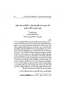
3. Simulation of bogie, suspension and multibody dynamics The railway vehicle in general comprises a car body supported by two bogies one at each end. Bolsters are the intermediate members between the car bodies. Each bogie frame is connected to car body through side bearings as shown in Fig. 1. The bogie frame supports the car body weight through a secondary suspension located between the car body and bogie frame. Each bogie usually consists of two wheel axle sets that are connected through the primary suspension to the bogie frame. In addition, the wheels are usually tapered or profiled to provide a self centring action as the axle traverses on the track.
Fig. 1: A conventional freight car in lateral plane [95]
Necessary function of the rail vehicle suspension is to support adequately the vehicle body and its contents. Key concern in this area involves the dynamic loads exerted at the wheel/rail interface and the transmission of static loads to the rail bed. The suspension should ensure equal and uniform distribution of the loads through the components of the rail vehicle body to the track and should minimize the dynamic loads. The measure of the suspension support performance is the ratio of lateral to vertical loads (L/V ratio) at each wheel. It is desirable to keep this ratio as minimum as possible. This ratio is also referred to as the derailment quotient as it predicts the tendency of a vehicle to derail under certain conditions. In past several researchers have investigated the effects of various design parameters on the dynamic levels of L/V ratio [89 and 90]. Most investigators of bogie frame dynamics have assumed that the bogie frame is rigid. The connections between the wheelsets in their bearings and bogie frame have been treated as a rigid attachment or as a primary suspension system. In the former case, the resulting model has the yaw and lateral displacement degrees of freedom of the bogie frame. In the later case, the primary
Fig. 2: A typical Swedish passenger bogie frame (Source: Bombardier Transportation)
Fig. 3: A conventional North American freight bogie frame (Source: Bombardier Transportation)
In the past, investigators have shown thorough interest in analyzing dynamics of rail vehicles considering different degree of freedom bogie frames with rigid [84, 90 and 91] and non rigid primary suspension elements [84, 87, 90 and 91]. In the last 55
Sharma et al. 2012. Int. J. Vehicle Structures & Systems, 4(2), 52-63
twenty-five years, very complex, nonlinear vehicle models, with many degrees of freedom were developed for the simulations of vehicle dynamics problems. Increase of computer power allowed certain vehicle characteristics, which were not obtainable by analytical studies. Rail vehicle multibody simulation has also progressed a long way from its origins as a research tool. Modern multibody software packages e.g. GENSYS are used as an essential part of the design process for new vehicles and for investigating service problems with existing vehicles. Increasingly, simulation is being used as part of the vehicle acceptance process in place of on-track testing [14 and 15]. J. Evans and M. Berg in their state of the art paper focussed on appropriate modelling choices for different applications and discussed about the best practice for the idealisation of suspension components, wheel-rail contact conditions and modelling inputs such as track geometry. Multibody dynamics in combination with genetic algorithm or sequential quadratic programming is utilized for optimization of performance indices of rail vehicle. Yuping and McPhee [36 and 43] have presented new set of suspension, inertial and geometric parameters for optimized stability and curving performance. Hardware in the loop (HIL) techniques are presently utilized for the analysis of multibody simulations of railway vehicle [22]. HIL techniques are widely used for fast prototyping of control systems, electronic and mechatronic devices.
The term spin creep refers to the ratio of the relative angular velocity about an axis normal to the contact area to the forward speed V. The constants of proportionality are called creep coefficients. Generally, the creep force vector is resolved into lateral and longitudinal components in the plane of the contact area between the wheel and rail. The lateral component is comprised of a term due to the lateral creep and a term due to the spin creep. The longitudinal component of the creep force vector consists of a single term due to the longitudinal creep force. The creep moment vector about an axis normal to the contact area is comprised of a term due to the lateral creep and a term due to the spin creep. The shape of the contact area between the wheel and rail as calculated with Hertz theory is elliptical. The length of the major and minor axes and the distribution of the normal load between the bodies across the contact area can be determined from the Hertz theory for two elastic bodies in contact. The creep analysis considers the contact area into a locked adhesion region and an interfacial slip region. Within the contact region, Coulomb’s law of friction is assumed to be valid.
4.1. Two dimensional theories The problem of creep for railway vehicle was first considered by Carter in 1926 taking into account twodimensional theory of rolling contact with friction. In 1958, Johnson [93] extended Carter’s two-dimensional theory to a three dimensional case of two rolling spheres in which the longitudinal and lateral creepages were included without spin creep. In 1964, Johnson and Vermeulen [92] extended the theory of arbitrary smooth half-spaces to pure creepages without spin creep. Accordingly, the contact surface between the rolling bodies transmitting a tangential force was asymmetrically divided into a slip region and a stick/noslip region. In 1967, Kalker [102] developed a linear theory of rolling contact, which suggested that for small creepages the area of slip is so small such that its influence can be neglected. Therefore, the adhesion region can be assumed to cover the entire area of contact. Kalker’s linear theory is valid only for small creepage and spin where creep coefficients are dependent on elliptic contact, normal load, and elastic constants. Kalker’s linear theory is widely used in railway vehicle dynamics to determine the lateral stability and to establish the slip boundaries for steady-state curving forces. However linear creep theory does not predict gross sliding and thus cannot be used to investigate effects associated with this type of behaviour. Kalker has formulated two non linear creep laws that were generally referred to as the ‘simplified theory’ of rolling contact [101] by incorporating the effects of spin creepage. The differences in the solution lie in two simplifying assumptions made concerning the tangential displacement-stress relationship and the normal stress distribution on the contact surface. These assumptions reduce the computation time and restricted to the case where the two bodies are of the same material. On the basis of Kalker’s simplified theory of rolling contact, computer programs such as SIMROL, ROLCON and FASTSIM were developed. SIMROL and FASTSIM
4. Wheel-Rail Interaction If the aerodynamic forces are neglected, the only external forces acting on a railway car besides its weight are due to the interaction at the wheel-rail contact. As the wheel set moves along the rails and undergoes yaw and lateral motion, both the wheels and the rails will deform elastically at the contact regions. Creep forces and moments arise due to the difference in strain rates of the wheel and rail in the contact region. The relationship between the creep force and the relative strain rate is shown in Fig. 4. The variation of creep moment with creepage is qualitatively similar. Linear creep theory asserts that the creep forces and moments are directly proportional to the product of the relative linear and angular velocities of wheel and rail at the point of contact. These non-dimensional ratios of linear velocities are called lateral or longitudinal creep depending upon the direction of the relative linear velocity.
Fig. 4: Creepage/creep force relationship [100]
56
Sharma et al. 2012. Int. J. Vehicle Structures & Systems, 4(2), 52-63
[73] were written by Kalker. ROLCON was written by Knothe. FASTSIM has been used by a number of researchers to directly calculate creep forces for all contact of a rail vehicle at every iteration of the simulation. This method is used by MEDYNA [98].
The theoretical curves are valid for contact point quantities whereas the experimental results have been measured at the axle [51]. However, qualitatively the deviations remain the same, even if the same quantities are used for theory and measurement. The important development in rolling contact theory with the recent advances made in the field of flexible multibody dynamics can serve as the foundation for developing new computational methods for railroad vehicle/track systems design and analysis [49]. Multibody computational methods can be used to simulate the following: Dynamic effects due to the structural flexibility of the vehicle components and the track. Multiple coupled railway cars negotiating variable track geometry. Derailments resulting from gauge widening. Three-dimensional wheel/rail contact. Vehicle track interaction. Vehicle dynamics under high operating speeds. The movement of the wheelsets along the rail is characterized by a complex contact with relative motions in the longitudinal and lateral directions and relative rotations of the wheels with respect to the rails. Based on new developments in rolling contact theory, one can predict the contact forces between the wheel and rail when realistic kinematic and dynamic descriptions are provided at the contact points. Basic quantities such as longitudinal, lateral and spin creepages are essential for accurately predicting the contact forces. In many investigations, linearized or partially linearized kinematic expressions are used to define the creepages. In the recent past, a generic wheel-rail contact detection formulation [28] is presented in order to determine the contact points, even for the most general threedimensional motion of the wheel set. The guidance of railway vehicles is determined by a complex interaction between the wheels and rails, which requires a detailed characterization of the contact mechanism in order to permit a correct analysis of the dynamic behaviour. The kinematics of guidance of the wheelsets is based on the wheel and rail geometries. Equivalent conicity is widely used to characterise the wheel/rail contact geometry. However, it does not consider the contact nonlinearity [10]. Polach [10] evaluated the influence of the contact nonlinearities on the behaviour of railway vehicles at the stability limit and presented a new and innovative description of wheel/rail contact geometry. Researchers [46] have also assessed the feasibility of applying an ultrasonic technique for investigating the contact problems between the wheel and rail. In particular, the size and shape of the contact area have been determined with a good agreement between the experimental data and Hertz’s theory. Real contact area has also been evaluated. Experimental results have demonstrated that under normal loads (i.e. for contact pressures of 600–800 MPa), the contact area is a small fraction of the nominal one depending up on the initial roughness of the surfaces in contact. Advanced modelling of rail vehicle dynamics requires realistic solutions of contact problems for wheels and rails that are able to describe contact
4.2. Three dimensional theories Kalker also presented theories [77] that consider a complete three-dimensional, non-linear solution of the rolling contact problem. Kalker analyzed the case of large creepage and spin in his numerical theory and tabulated the results in a non-dimensional form. At large creepage, all three force components are generally functions of all three creepage components. At very large creepage, the entire contact degenerates to the case of pure sliding. Kalker’s ‘complete theory’ was embodied in a program named DUVOROL, which is able to predict for larger values of a/b. This method has been used in order to extend the table of nondimensional creep force-creepage data up to a/b of 10. The program DUVOROL exists in both ALGOL and FORTRAN versions. Although FASTSIM is considerably faster than DUVOROL, this process is likely to be significantly more time consuming than interpolating a precomputed table generated using the more complete theory embodied in DUVOROL. Kalker’s program CONTACT is able to deal with arbitrary surfaces of two contacting bodies, which results in non-elliptic contact patches. Longitudinal, lateral and spin creep are considered in CONTACT. CONTACT can provide linear and non-linear, steady state as well as non steady-state solutions for the contact problems. Therefore, CONTACT is used for many practical problems. However CONTACT has certain limitations that the computational time associated with CONTACT is so high and is difficult to use online. In CONTACT both wheel and rails are considered to be elastic half spaces. This assumption is justified as long as the contact dimensions are smaller than the curving radii. CONTACT is unable to deal with plastic deformation in the rail head. Kalker along with the other investigators have also formulated non-linear creep theories which have been validated later on through experiments [72]. The work of Kalker has been summarized in a research paper [26]. In the past, it has been tried several times to validate the creep-force/creep relations that were calculated within the frame of Kalker’s simplified and complete theories.
4.3. Recent research in rolling contact theories In recent years new experimental results have been obtained due to the development of modern drive systems. The experimental results show the following deviations from the theoretical results: The measured curves show larger dispersion than those from the theoretical relationship. For the maximum value of the measured traction force, higher creepage is obtained than theoretical creepage. Beyond the maximum creepage, the measured traction forces decrease whereas a constant traction force is obtained in the theory. 57
Sharma et al. 2012. Int. J. Vehicle Structures & Systems, 4(2), 52-63
singularities [38]. The basic singularities demonstrate themselves as double and multiple contact patches. Solutions to the problems of multipoint contact can be obtained by method of virtual penetration or quasiHertzian cases. This method allows the calculation of non-elliptical, multipoint contact patches and creep forces during integration of the model leading to nearly real-time simulations. In another study [23], semielliptical normal pressure distribution in the direction of rolling was assumed and the contact area was found by virtual penetration of wheel and rail.
typical of the exposures. The considered frequency ranges for motion sickness and comfort are 0.1Hz 0.5Hz and 0.5Hz - 80Hz respectively. ISO 2631 [97] defines the ride comfort using frequency weighted RMS acceleration (aW(t) in m/s2) as: 1
1 T 2 aW aW2 (t ) dt T 0
(5)
Where T is the duration of measurements in seconds. Table 1: Sperling’s ride evaluation scales [100]
Ride quality (Wz) 1 – Very good 2 – Good 3 – Satisfactory
5. Ride Quality and Comfort During the last fifty years, there have been many attempts in defining the technical measures and evaluation criteria to quantify the ride comfort for an average passenger in a train. These attempts have been accelerated since 1980 leading to proposals for standards from ISO, CEN and UIC/ERRI. However, in the area of motion sickness much research is still to be done, in particular related to the motions of tilting trains. Traditionally, ride comfort is investigated in the nonaudible frequency range of 0.5-20 Hz. However, the new proposed ISO and CEN standards recommend that vibrations up to 80 Hz should be considered. If the risk of motion sickness is to be evaluated, the frequency range below 0.5 Hz should be considered as well.
4 – Acceptable for running 4.5 – Not acceptable for running 5 – Dangerous
Ride comfort (RI) 1 – Just noticeable 2 – Clearly noticeable 2.5 – More pronounced but not unpleasant 3 – Strong, irregular, but still tolerable 3.25 – Very irregular 3.5 – Extremely irregular, unpleasant, annoying, prolonged exposure intolerable 4 – Extremely unpleasant, prolonged exposure harmful
Human sensitivity to vibratory motions in the 0.1 to 20Hz frequency range is the primary concern in evaluating vehicle ride. ISO comfort criteria for vibratory accelerations are usually given in terms of limits or ‘isocomfort’ curves for vertical RMS and lateral RMS acceleration as a function of frequency shown in Fig. 5. These curves are based on human sensitivity data obtained by subjecting human subjects at discrete frequencies, and are considered as an international basis of evaluating the rail vehicle ride quality.
5.1. Sperling’s Ride Indices In estimating the ride quality, the vehicle itself is judged. Ride comfort implies that the vehicle is to be assessed according to the effect of mechanical vibrations on the occupants. The ride quality and ride index are evaluated from the measured accelerations on the floor of the vehicle over defined time intervals or track sections (e.g. each km interval). Sperling’s ride quality (Wz) and ride comfort (RI) are defined as: Wz 0.896 (a 3 / f )1/10 RI 0.896 [( a 3 / f ) F ( f )]1 / 10 (1) Where a is the acceleration amplitude (in cm/s2) measured on the inner floor of the vehicle (laterally and vertically), F (f) is frequency weighting factor which expresses human vibration sensitivity and is different for vertical and horizontal vibration components. With the introduction of electronic instruments in evaluations of ride quality and comfort, the ride index equations were put in the following forms without changing their contents: (2) Wz (a 3 B 3 )1/10 RI (a 2 B 2 )1 / 6.67 Where B is the acceleration weighting factor. In order to judge the ride quality and ride comfort, rail vehicle is accessed on Sperling’s ride evaluation scales mentioned in Table 1.
5.2. ISO 2631 and CEN Standards for comfort
Fig. 5: Recommended ISO ride comfort limits [95]
According to ISO 2631 [97] vibration which is transmitted to the body shall be measured on the surface between the body and its supported surface. However until 1998, this has just been made to a very limited extent in rail vehicles, where traditional vibrations are measured on the floor. The duration of measurement shall be sufficient to ensure that the assessed vibration is
European committee of normalisation proposes the mean value of ride comfort (NMV) using: rms 2 rms 2 rms 2 N MV 6 (aWxpd95 ) (aWypd95 ) (aWzpb95 )
(6)
Where individual terms under the root are accelerations (in m/s2) measured or calculated on the vehicle inner 58
Sharma et al. 2012. Int. J. Vehicle Structures & Systems, 4(2), 52-63
floor, in three directions (x = longitudinal, y = lateral, x y parallel to the floor, z = vertical. i.e. perpendicular to the floor). The three accelerations are the 95th percentiles of at least 60 RMS values each taken over 5 seconds. Each acceleration has been filtered with filters Wd (for longitudinal and lateral) and Wb (for vertical).
Facchinetti et al [6] performed full-scale laboratory experiments in order to derive reliable suspension models with their quasi-static and dynamic behaviour. The air spring suspension has been modelled using a quasi-static approach where the frequency-dependent behaviour of the suspension is neglected and the coupling between shear and roll stiffness is included. The frequency-dependent behaviour of suspension in vertical direction is represented using a thermodynamic model.
5.3. Recent research in ride comfort evaluation The random vehicle motions can be best expressed in terms of power spectral density (PSD) that describes the intensity of the random vibration at a certain frequency. The area under the PSD curve in any frequency band is the mean square value of the response in that band. In summary, an analytical study of the riding quality of a railway vehicle entails the computation or simulation of the random motion of the vehicle body in response to the random irregularities of the rail bed. The rail bed irregularity inputs to such analysis can be either in the form of time series data of actual rail bed irregularities or in the power spectral density format depending on the requirements of the subsequent analysis. In past investigators have done extensive research work on analyzing the ride quality and ride comfort considering different types of railway vehicles i.e. highspeed rail vehicle, Maglev rail vehicle, tilting train etc [16, 19, 41, 44 and 48]. In a recent analysis, a new method for an objective evaluation of ground vehicle ride comfort is presented [18]. In this study, the ride comfort in the frequency range from 0-30 Hz has been referred to the acceleration acting along the vertical axis (subject spine) and the longitudinal acceleration (acting at the subject shoulders). Based on the experimental measurements of such accelerations on different human subjects seated on the car seat, appropriate mathematical models of the seat and subject have been derived. In order to improve the ride comfort of lightweight railway vehicles, an active vibration reduction system using piezo-stack actuators is proposed and studied in simulations [27]. The system consists of actuators and sensors mounted on the vehicle car body. The output signals of the sensors which are measuring the flexible deformation of the car body generate a bending moment, which is directly applied to the car body by the actuators via a feedback control loop. This bending moment reduces the structural vibration of the vehicle car body. Ride quality in the context of recent research may be evaluated using synthesized performance analysis with model parameters (SWAMP) method [25]. With the SWAMP method, relationship between modal and physical parameters is built at first with a unified ‘trackvehicle-human’ model. Then they are used with experimentally identified modal parameters and PSD responses to find ways to improve ride quality. The introduction of secondary air spring suspension system in high-speed railway vehicle and its effects on the ride quality and ride safety has also been the interest of researchers [6 and 11] in the recent past. It is found that active control of secondary air spring suspension system reduces the vertical and pitch oscillations in low frequency range [11]. The results obtained from the analysis indicate that active suspension control offers an important improvement on ride quality, by far larger than achievable with semi-active suspensions [11].
6. Linear and nonlinear analyses Linear equations of motion can be obtained if we make small displacement assumptions and ignore such nonlinear characteristics such as clearance between components, suspension stops, the wheel flange, dry friction in suspension components, and the adhesion limits between the wheel and rail. The creep force terms, describing the tangential forces at the wheel/rail interface, give rise to much of the interesting (as well as destructive) behaviour of railway vehicles. These equations describe non-conservative mechanical systems. The non-conservative nature of these equations arises from the coupling terms due to creep and wheel taper. Consequently, solutions may be stable or unstable. Wickens carried out an interesting energy analysis of the wheel set equations [90 and 91]. The explicit analysis shows how creep and conicity lead to instability. The forward velocity of the wheel set appears explicitly in the equations, and is one of the parameter that determines stability of the solutions of the equations. The approach of finding approximate values of critical speed through stability analysis of the linear equations of motion has been extensively used by different researchers [84, 89, 90 and 91]. The linear equations of motion also apply to vehicle behaviour in curves by including the terms for centripetal acceleration and rail cant and assuming that the motions are small enough to ensure that slip or flange contact does not occur. Stiff bogie do not meet these requirements for curving without flange contact, but researchers have investigated the possibility of designing vehicles that will curve without flange contact [86 and 87]. The practical use of the linear analysis has been reduced to a minimum with the broad use of MBS computer program for dynamic simulations. Presently the non-linear analysis of rail-vehicle dynamics is the standard whereas linear approach is used mainly for testing the consistency of the MBS model. The important problem for non-linear models is a proper treatment of elements with non-smooth characteristics leading to impacts during collision of elements and characteristics of elements with pre-tension and dry friction. Realistically rail vehicle dynamics problems can be dealt using nonlinear dynamics [33, 54, 63 and 96]. The concept of a phase space is introduced by True in order to illustrate the dynamics of nonlinear systems in a way that is easy to perceive. It is investigated that the analysis of nonlinear dynamic problems always should start with an analysis of the equilibrium states of the full nonlinear problem whereby great care must be taken in the choice of the numerical 59
Sharma et al. 2012. Int. J. Vehicle Structures & Systems, 4(2), 52-63
solvers [54]. When the equilibrium states are known certain linearization around one chosen state may be applied carefully in order to facilitate or speed up the numerical solution of the dynamical problem. However, it is stated that certain problems cannot be linearized and it is necessary to know the equilibrium states of the full nonlinear system before the simulation calculations are performed. There has been relatively little analysis of railway car dynamics that consider nonlinear effects. There are nonlinearities in these systems that may be expected to influence the dynamics appreciably. The factors of curved wheel profiles, nonlinear creep, flange contact, and nonlinear suspension characteristics strongly affect wheel set and bogie hunting. The analyses concerned with these effects have concentrated mainly on the dynamics of wheelsets or bogie rather than complete vehicles. With few exceptions, most of the studies of the effects of nonlinearities have utilized either analogue or digital computers to integrate the equations of motion. Several researchers [57, 61, 69, 84 and 89] have studied the rail dynamics with non linear equations of motion considering different models of rail vehicle system.
more accurate results from simulations as compared to actual testing results, further investigations are required to be performed for a realistic curved or worn wheel and rail profiles and an exact non linear creep analysis. In the past railway track structure and substructure have been modelled considering it to be discrete or continuous. However, these models have been found to be difficult to incorporate with a complete vehicle system due to mathematical complexity. This aspect needs to be investigated. It is necessary to develop a realistic characterization of the rail bed in modelling that allows the successful prediction of vehicle motions without complexity. If the model is too complex, the utility of the model will suffer due to the difficulties in supplying accurate input data, solving the resulting equations and interpreting the results. REFERENCES: [1] K.R. Rajeev, M.P. Garg and R.C. Sharma. 2012. Vibration analysis of radial drilling machine structure using finite element method, Advanced Materials Research, 272-275, 2717-2721. [2] R.C. Sharma. 2011. Ride analysis of an Indian Railway coach using Lagrangian dynamics, Int. J. Vehicle Structures & Systems, 3(4), 219-224. [3] R.C. Sharma. 2011. Parametric analysis of rail vehicle parameters influencing ride behavior, Int. J. Engg. Sci. & Tech., 3(8), 54-65. [4] R.C. Sharma. 2011. On the air braking system and calculation of braking distance of Indian Railways, Indian Railway Technical Bulletin, 68(339), 8-10. [5] S. Bruni, J. Vinolas, M. Berg, O. Polach and S. Stichel. 2011. Modelling of suspension components in a rail vehicle dynamics context, Vehicle System Dynamics, 49(7), 1021-1072. http://dx.doi.org/10.1080/00423114. 2011.586430 [6] A. Facchinetti, L. Mazzola, S. Alfi and S. Bruni. 2010. Mathematical modeling of the secondary airspring suspension in railway vehicles and its effect on safety and ride comfort, Vehicle System Dynamics, 48(1), 429-449. http://dx.doi.org/10.1080/00423114.2010.486036 [7] A. Wetzel and C. Proppe. 2010. On reliability and sensitivity methods for vehicle systems under stochastic crosswind loads, Vehicle System Dynamics, 48(1), 79-95. http://dx.doi.org/10.1080/00423110903183917 [8] J. Piotrowski. 2010. Smoothing dry friction damping by dither generated in rolling contact of wheel and rail and its influence on ride dynamics of freight wagons, Vehicle System Dynamics, 48(6), 675-703. http://dx.doi.org/10. 1080/00423110903126478 [9] J. Piotrowski. and P. Pazdzierniak. 2010. Influence of dither generated by rolling contact on friction damping in freight vehicles, Vehicle System Dynamics, 48(1), 195209. http://dx.doi.org/10.1080/00423111003706722 [10] O. Polach. 2010. Characteristic parameters of nonlinear wheel/rail contact geometry, Vehicle System Dynamics, 48(1), 19-36. http://dx.doi.org/10.1080/0042311100 3668203 [11] S. Alfi, S. Bruni, E. Gialleonardo and A. Facchinetti. 2010. Active control of airspring secondary suspension for improving ride comfort in presence of random track irregularity, J. Mech. Sys. Trans. & Logistics, 3(1), 143153.
7. Concluding remarks and perspectives There are possibilities for the improvement in the modelling of vehicle system. In the past an exact or true modelling of a complete railway vehicle has not been carried out. A complete vehicle system has hardly been modelled with exact nonlinearities in suspension system due to complexity in computation. In a complete vehicle system suspension elements i.e. air springs, bump stops etc need to be more accurately modelled accounting for their nonlinearities realistically. Rigid bodies are not rigid in actual behaviour. They have to be more accurately modelled with adequate flexibility. In past there has been extensive work done by the researchers to study the lateral dynamics of rail vehicle. Few authors have also studied vertical dynamics. In practice, the travel of rail vehicle on track is always a coupled motion between vertical and lateral traverse of the vehicle. The vertical irregularities of the track cause both vertical and lateral vibrations in the rail vehicle. In addition, the different rigid bodies i.e. car body, bolsters, bogie frames and wheel axles set execute different angular motions which influence the dynamic behaviour of the rail vehicle system significantly. In developing the mathematical model to study vertical response, it would not be adequate to include bounce, pitch and roll degrees of freedom of the components but yaw and lateral degrees of freedom also need to be considered. On the other hand, for the lateral response model, it would not be sufficient to use lateral, yaw and roll degrees of freedom of the components but vertical and pitch motions need to be considered. As the track is a major source of the forces acting on the wheels of the railway vehicle, a better understanding of the fundamental aspects of wheel/rail interaction is necessary. Despite of sufficient investigations, researchers are unable to explain the large discrepancies that occur between the measured and theoretically predicted values of creep coefficients. In order to obtain 60
Sharma et al. 2012. Int. J. Vehicle Structures & Systems, 4(2), 52-63 [12] A.C. Mellado, C. Casanueva, J. Vinolas and J.G. Gimenez. 2009. A lateral active suspension for conventional railway bogies, Vehicle System Dynamics, 47(1), 1-14. http://dx.doi.org/10.1080/0042311070 1877512 [13] C. Baker, F. Cheli, A. Orellano, N. Paradot, C. Proppe and D. Rocchi. 2009. Cross-wind effects on road and rail vehicles, Vehicle System Dynamics, 47(8), 983-1022. http://dx.doi.org/10.1080/00423110903078794 [14] C. Weidemann. 2009. State of the art railway vehicle design with multi-body simulation, J. Mech. Sys. Trans. & Logistics, 3(1), 12-26. [15] J. Evans and M. Berg. 2009. Challenges in simulation of rail vehicle dynamics, Vehicle System Dynamics, 47(8), 1023-1048. http://dx.doi.org/10.1080/004231109030 71674 [16] J. Lee, S. Kwon, M. Kim and I. Yeo. 2009. A parametric study on the dynamics of urban transit maglev vehicle running on flexible guideway bridges, J. Sound & Vibration, 328(3), 301-317. http://dx.doi.org/10.1016/j. jsv.2009.08.010 [17] J. Santmaria, E.G. Vadilo and J. Gomez. 2009. Influence of creep forces on the risk of derailment of railway vehicles, Vehicle System Dynamics, 47(6), 721-752. http://dx.doi.org/10.1080/00423110802368817 [18] M. Pennati, M. Gobbi, and G. Mastinu. 2009. A dummy for the objective ride comfort evaluation of ground vehicles, Vehicle System Dynamics, 43(6-7), 343-362. http://dx.doi.org/10.1080/00423110802109724 [19] R. Persson, R.M. Goodall, and K. Sasaki. 2009. Carbody tilting-technologies and benefits, Vehicle System Dynamics, 47(3), 949-981. http://dx.doi.org/10.1080/ 00423110903082234 [20] V. Kumar and V. Rastogi. 2009. Investigation of vertical dynamic behavior and modelling of a typical indian rail road vehicle through bond graph, World J. Modelling & Simulation, 5(2), 130-138. [21] W.M. Zhai, K. Wang and C. Cai. 2009. Fundamentals of vehicle-track coupled dynamics, Vehicle System Dynamics, 47(11), 1349-1376. http://dx.doi.org/10.1080/ 00423110802621561 [22] E. Meli, M. Malvezzi, S. Papini, L. Pugi, M. Rinchi and A. Rindi. 2008. A railway vehicle multibody model for real time applications, Vehicle System Dynamics, 46(12), 1083-1105. http://dx.doi.org/10.1080/0042311070179 0756 [23] J. Piotrowski and W. Kik. 2008. A simplified model of wheel/rail contact mechanics for non-Hertzian problems and its application in rail vehicle dynamic simulations, Vehicle System Dynamics, 46(1-2), 27-48. http://dx.doi.org/10.1080/00423110701586444 [24] J. Pompo and J. Ambrosio. 2008. Application of a wheelrail contact model to railway dynamics in small radius curves, Multibody System Dynamics, 19(1-2), 91-114. http://dx.doi.org/10.1007/s11044-007-9094-y [25] J. Zhou, G. Shen, H. Zhang and L. Ren. 2008. Application of model parameters on ride quality improvement of railway vehicles, Vehicle System Dynamics, 46(1), 629641. http://dx.doi.org/10.1080/00423110802033049 [26] K. Knothe. 2008. History of wheel/rail contact mechanics from Redtenbacher to Kalker, Vehicle System Dynamics, 46, (1-2), 49-66. http://dx.doi.org/10.1080/00423110701 590180 [27] G. Schandl, P. Lugner, C. Benatzkyb, M. Kozekb and A. Stribersky. 2007. Comfort enhancement by an active
[28]
[29]
[30]
[31]
[32]
[33]
[34]
[35]
[36]
[37]
[38]
[39]
[40]
[41]
[42]
61
vibration reduction system for a flexible railway car body, Vehicle System Dynamics, 45(9), 835-847. http://dx.doi.org/10.1080/00423110601145952 J. Pompo, J. Ambrosio and M. Silva. 2007. A new wheelrail contact model for railway dynamics, Vehicle System Dynamics, 45(2), 165-189. http://dx.doi.org/10.1080/ 00423110600996017 J. Shi, Q. Wei and Y. Zhao. 2007. Analysis of dynamic response of high speed EMS maglev vehicle/guideway coupling system with random irregularity, Vehicle System Dynamics, 45(12), 1077-1095. http://dx.doi.org/10.1080/ 00423110601178441 K.V. Gandadharan, C. Sujatha and V. Ramamurti. 2007. Dynamic response of railroad vehicle to rail joints and average vertical profile: A time domain approach, Int. J. Heavy Vehicle Systems, 14(4), 402-420. K.V. Gandadharan, C. Sujatha and V. Ramamurti. 2007. Dynamic response of rail road vehicles: A Frequency Domain Approach, Int. J. Heavy Vehicle Systems, 15(1), 65-81. http://dx.doi.org/10.1504/IJHVS.2008.017984 B.H. Park, N.P. Kim, J.S. Kim and K.Y. Lee. 2006. Optimum design of tilting bogie frame in consideration of fatigue strength and weight, Vehicle System Dynamics, 44(12), 887-901. http://dx.doi.org/10.1080/ 00423110600737106 H. True. 2006. Advances in the fundamental understanding of railway vehicle dynamics, Int. J. Vehicle Design, 40(1-3), 251-264. http://dx.doi.org/10.1504/ IJVD.2006.008481 M.J.M.M. Steenbergen. 2006. Modeling of wheels and rail discontinuities in dynamic wheel-rail contact analysis, Vehicle System Dynamics, 44(10), 763-787. http://dx.doi.org/10.1080/00423110600648535 R.M. Goodall, S. Bruni and T.X. Mei. 2006. Concepts and prospects for actively controlled railway running gear, Vehicle System Dynamics, 44(1), 60-70. http://dx.doi.org/ 10.1080/00423110600867374 H. Yuping and J. McPhee. 2005. Optimization of curving performance of rail vehicles, Vehicle System Dynamics, 43(12), 895-923. http://dx.doi.org/10.1080/ 00423110500177445 J.B. Ayasse and H. Chollet. 2005. Determination of the wheel rail contact patch in semi-Hertzian conditions, Vehicle System Dynamics, 43(3), 161-172. http://dx.doi.org/10.1080/00423110412331327193 J. Piotrowski and H. Chollet. 2005. Wheel-rail contact models for vehicle system dynamics including multi-point contact, Vehicle System Dynamics, 43(6-7), 455-483. http://dx.doi.org/10.1080/00423110500141144 G. Chen and W.M. Zhai. 2004. A new wheel/rail spatially dynamic coupling model and its verification, Vehicle System Dynamics, 41(4), 301-322. http://dx.doi.org/ 10.1080/00423110412331315178 T.X. Mei and R.M. Goodall. 2003. Practical strategies for controlling railway wheelsets with independently rotating wheels, J. Dyn. Sys., Meas. Control, Trans. ASME, 125, 354-360. C.F. Zhao and W.M. Zhai. 2002. Maglev vehicles/guideway vertical random response and ride quality, Vehicle System Dynamics, 38(3), 185-210. http://dx.doi.org/10.1076/vesd.38.3.185.8289 G. Diana. 2002. Active control of the running behaviour of a railway vehicle: stability and curving performances, Vehicle System Dynamics Supplement, 37, 157-170.
Sharma et al. 2012. Int. J. Vehicle Structures & Systems, 4(2), 52-63 [43] H. Yuping and J. McPhee. 2002. Optimization of the lateral stability of rail vehicles, Vehicle System Dynamics, 38(5), 361-390. http://dx.doi.org/10.1076/vesd.38.5.361. 8278 [44] M. Gotsch and M. Sayir. 2002. Simulation of the riding comfort of railway coaches, Vehicle System Dynamics, 37, 630-640. [45] M. Gretzschel and L. Bose. 2002. A new concept for integrated guidance and drive of railway running gears, Control Engineering Practice, 10, 1013-1021. http://dx.doi.org/10.1016/S0967-0661(02)00046-1 [46] M. Pau, F. Aymerich and F. Ginesu. 2002. Distribution of contact pressure in wheel rail contact area, Wear, 253 (12), 265-274. http://dx.doi.org/10.1016/S0043-1648(02) 00112-6 [47] O. Polach. 2002. Coupled single axle running gear- A new radial steering design, Proc. Instn. Mech. Engrs, J. Rail & Rapid Transit, 216(3F), 197-206. http://dx.doi.org/ 10.1243/095440902760213620 [48] P. Carlbom and M. Berg. 2002. Passengers, seats and carbody in rail vehicle dynamics, Vehicle System Dynamics, 37, 290-300. [49] A.A. Shabana and J.R. Sany. 2001. A survey of rail vehicle track simulations and flexible multibody dynamics, Nonlinear Dynamics, 26(2), 179-212. http://dx.doi.org/10.1023/A:1012976302105 [50] G.R.M. Mastinu and M. Gobbi. 2001. On the optimal design of railway passenger vehicles, Proc. Instn. Mech. Engrs., 215(F), 111-123. [51] K. Knothe, R. Wille and B.W. Zastrau. 2001. Advanced contact mechanics-road and rail, Vehicle System Dynamics, 35(4-5), 361-407. http://dx.doi.org/10.1076/ vesd.35.4.361.2043 [52] A. Chudzikiewicz. 2000. Simulation of rail vehicle dynamics in Matlab environment, Vehicle System Dynamics, 33, 107-119. http://dx.doi.org/10.1076/00423114(200002)33:2;1-1;FT107 [53] J.F. Garcia, X. Olaizola, L.M Martin and J.G. Gimenez. 2000. Theoretical comparison between different configuration of radial and conventional bogies, Vehicle System Dynamics, 33(4), 233-259. http://dx.doi.org /10.1076/0042-3114(200004)33:4;1-U;FT233 [54] H. True. 1999. On the theory of nonlinear dynamics and its applications in vehicle systems dynamics, Vehicle System Dynamics, 31(5-6), 392-421. http://dx.doi.org/ 10.1076/vesd.31.5.393.8361 [55] R.V. Dukkipati. 1999. A parametric study of the lateral stability of a rail bogie on a roller rig, Proc. Instn. Mech. Engrs, 213(F), 39-47. [56] R.V. Dukkipati and S. Narayanaswamy. 1999. Performance of a rail car equipped with independently rotating wheelsets having yaw control, Proc. Instn. Mech. Engrs, 213, 31-38. http://dx.doi.org/10.1243/ 0954409991531001 [57] M. Berg. 1998. A non-linear rubber spring model for rail vehicle dynamic analysis, Vehicle System Dynamics, 197212. http://dx.doi.org/10.1080/00423119808969447 [58] R.V. Dukkipati. 1998. Dynamics of a wheelset on roller rig, Vehicle System Dynamics, 44(3), 409-430. http://dx.doi.org/10.1080/00423119808969458 [59] A. Powell. 1997. Mechatronic control of an actively guided rail vehicle, Vehicle System Dynamics Supplement, 33, 442-452. [60] G. Shen and R.M. Goodall. 1997. Active yaw relaxation for improved bogie performance, Vehicle System
[61]
[62] [63]
[64]
[65]
[66]
[67]
[68]
[69]
[70]
[71]
[72]
[73]
[74]
[75]
[76]
[77]
[78]
62
Dynamics, 28, 273-289. http://dx.doi.org/10.1080/ 00423119708969357 M. Berg. 1997. A model for rubber springs in the dynamic analysis of rail vehicles, Proc. Instn. Mech. Engrs., 211 (F), 95-108. M. Hughes. 1997. Tilt nausea is bad business, Railway Gazette Int., 153 (4), 249. H. True and J.C. Jensen. 1994. Parameter study of hunting and chaos in railway vehicle dynamics, Vehicle System Dynamics, 23(1), 508-521. http://dx.doi.org/10.1080/ 00423119308969537 S. Narayanswami, R.V. Dukkipati and M. Osman. 1994. A comparative study on lateral stability and steady state curving behavior of unconventional rail truck models, Proc. Instn. Mech. Engrs, 208(16), 1-13. http://dx.doi. org/10.1243/PIME_PROC_1994_208_228_02 S. Narayanswami, R.V. Dukkipati and M. Osman. 1994. Analysis of modified railway passenger truck designs to improve lateral stability/curving behaviour compatibility, Proc. Instn. Mech. Engrs., 209(1), 49-59. W. Kortum. 1993. Review of multibody computer codes for vehicle system dynamics, Vehicle System Dynamics, 22(1), 3-33. http://dx.doi.org/10.1080/ 00423119308969463 A.H. Wickens. 1991. Steering and stability of the bogie: Vehicle dynamics and suspension design, Proc. Instn. Mech. Engrs., 205(F2), 109-122. B.M. Eickhoff. 1991. The application of independently rotating wheels to railway wheels to railway vehicles, Proc. Instn. Mech. Engrs., 205(1), 43-54. http://dx.doi. org/10.1243/PIME_PROC_1991_205_215_02 I.A. Castelazo and J.K. Hedrick. 1989. Stability analysis of a nonlinear wheelset rolling on rough track, J. Dyn. Sys., Meas. Control, Trans. ASME, 111, 277-285. A.H. Wickens. 1988. Stability optimization of multi-axle railway vehicles possessing perfect steering, J. Dyn. Sys., Meas. Control, Trans. ASME, 110, 1-7. J. Lieh and I. Haque. 1988. Parametrically excited behavior of a railway wheelset, J. Dyn. Sys., Meas. Control, Trans. ASME, 110, 8-17. J.A. Elkins and B.M. Eickhoff. 1982. Advances in nonlinear wheel/rail force prediction methods and their validation, J. Dyn. Sys., Meas. Control, Trans. ASME, 104, 133-142. J.J. Kalker. 1982. A fast algorithm for the simplified theory of rolling contact, Vehicle System Dynamics, 11, 113. http://dx.doi.org/10.1080/00423118208968684 C.E. Bell, D. Horak and J.K. Hedrick. 1981. Stability and curving mechanics of rail vehicles, J. Dyn. Sys., Meas. Control, Trans. ASME, 103, 181-190. C.E. Bell and J.K. Hedrick. 1981. Forced steering of rail vehicles ‘stability and curving mechanics’, Vehicle System Dynamics, 10, 357-386. http://dx.doi.org/10.1080/ 00423118108968683 D. Horak, C.E. Bell and J.K. Hedrick. 1981. A comparison of the stability and curving performance of radial and conventional rail vehicle trucks, J. Dyn. Sys., Meas. Control, Trans. ASME, 103, 191-200. J.J. Kalker. 1979. Survey of wheel-rail rolling contact theory, Vehicle System Dynamics, 5, 317-358. http://dx.doi.org/10.1080/00423117908968610 T.D. Burton and A.M. Whitman. 1978. Nonlinear kinematics of wheel-rail contact, J. Appl. Mech., 45, 664668. http://dx.doi.org/10.1115/1.3424378
Sharma et al. 2012. Int. J. Vehicle Structures & Systems, 4(2), 52-63 [79] A.H. Wickens. 1978. Stability criteria for articulated railway vehicles possessing perfect steering, Vehicle System Dynamics, 7, 168-182. http://dx.doi.org/10.1080 /00423117808968561 [80] A.H. Wickens. 1977. Static and dynamic stability of a class of three-axle railway vehicles possessing perfect steering, Vehicle System Dynamics, 6, 1-19. http://dx.doi.org/10.1080/00423117708968499 [81] M.G. Pollard. 1977. Studies of the dynamics of vehicles with cross-braced bogies, Vehicle System Dynamics, 6(23), 213-216. http://dx.doi.org/10.1080/004231177 08968544 [82] A.H. Wickens. 1975/76. Steering and dynamic stability of railway vehicles, Vehicle System Dynamics, 5, 15-46. http://dx.doi.org/10.1080/00423117508968404 [83] F.B. Blader and E.F. Kurtz. 1974. Dynamic stability of cars in long freight trains, J. Engg. Indu., Trans. ASME, 1159-1167. [84] N.K. Cooperrider. 1972. The hunting behavior of conventional railway trucks, J. Engg. Indu., Trans. ASME, 94(2), 752-762. http://dx.doi.org/10.1115/1.3428240 [85] A.H. Wickens. 1969. General aspects of the lateral dynamics of railway vehicles, J. Engg. Indu., Trans. ASME, 91(3), 869-878. http://dx.doi.org/10.1115 /1.3591720 [86] D. Boocock. 1969. Steady state motion of railway vehicles on curved track, J. Mech. Engg. Sci., 2(6), 556-566. http://dx.doi.org/10.1243/JMES_JOUR_1969 _011_069_02 [87] D. E. Newland. 1969. Steering a flexible railway truck on curved track, J. Engg. Indu., Trans. ASME, 91(3B), 908918. [88] H.C. Meachem and D.R. Ahlbeck. 1969. A computer study of dynamic loads caused by vehicle track interaction, J. Engg. Indu., Trans. ASME, 91(3B), 808816. [89] T. Matsudaira. 1966. Hunting problem on high speed railway vehicles with special reference to bogie design for the new Tokaido line, interaction between vehicle and track, Proc. Inst. Mech. Engrs, 180(3F), 58-66.
[90] A.H. Wickens. 1965. The dynamic stability of railway vehicle wheelsets and bogies having profiled wheels, Int. J. Solids & Structures, 1, 319-341. http://dx.doi.org/ 10.1016/0020-7683(65)90037-5 [91] A.H. Wickens. 1965. The dynamic stability of a simplified four-wheeled railway vehicle having profiled wheels, Int. J. Solids and Structures, 1, 385-405. http://dx.doi.org/ 10.1016/0020-7683(65)90004-1 [92] K.L. Johnson and P. L. Vermeulan. 1964. Contact of non spherical bodies transmitting tangential forces, J. Appl. Mech., 31, 338-340. http://dx.doi.org/10.1115/1.3629610 [93] K.L. Johnson. 1958. The effect of a tangential force upon the rolling motion of an elastic sphere upon a plane, J. Appl. Mech., 25, 339-346. [94] J. Zhou, G. Shen and R. Godall. 2009. Analysis of geometrical filtering phenomenon and resonant vibration suppression of flexible car body, Proc. 21st Int. Symp. Dyn. Vehicles on Roads and Tracks, Stockholm, Sweden. [95] R.V. Dukkipatti. 2000. Vehicle Dynamics, Narosa Publishing House, New Delhi. [96] W.M. Zhai and H. True. 1999. Vehicle-track dynamics on a ramp on the bridge: Simulation and measurement, Proc. 16th IAVSD Symp., Pretoria, South Africa. [97] ISO 2631. 1997. Mechanical Vibration and Shock Evaluation of Human Exposure to Whole Body Vibrations- Part 1: General Requirements. [98] C. Duffek. 1985. Analysis and simulation of rail and road vehicles with the program MEDYNA, Proc. 9th IAVSD Symp., Linkoping, Sweden. [99] J.J. Kalker. 1984. A simplified theory for non Hertzian contact, Proc. 8th IAVSD Symp. Cambridge, Mass., USA. [100] V.K. Garg and R.V. Dukkipatti. 1984. Dynamics of Railway Vehicle Systems, Academic Press, New York. [101] J.J. Kalker. 1973. Simplified Theory of Rolling Contact, Delft Progress Report, 1-10. [102] J.J. Kalker. 1967. On the rolling contact of two elastic bodies in the presence of dry friction, Ph.D. Dissertation, Delft University of Technology, Netherlands.
63