resolution Sigma-Delta ADC to estimate a set of digital error- correction .... modified sign-sign version of the LMS algorithm can be used. [11]:. ))((. )( ' )( )( iD sign.
A Background Calibration Scheme for Pipelined ADCs Including Non-linear Operational Amplifier Gain and Reference Error Correction A. Larsson, S. Sonkusale Texas A&M University Department of Electrical Engineering College Station, TX 77843 are mostly analog in nature. This makes them inapplicable in newer process technologies. Adaptive LMS based technique for calibration has been recently proposed in the literature, which are robust and scalable to newer digital CMOS process [6]-[9]. However all the above existing schemes correct for only few sources of errors like capacitor ratio mismatch and finite amplifier gain. They do not account for reference voltage errors or amplifier non-linearity which is posed to be a serious issue in newer nanometer-scale CMOS technologies. At high speeds, switching activity in pipeline will cause transient errors on reference voltage lines that will not settle within the given time period, causing huge distortions and inaccurate residue computation in pipeline. This will degrade the overall performance of the ADC. One scheme to calibrate for amplifier non-linearity is to switch between two possible residue curves using a random dither sequence and use a complex digital statistical estimation algorithm to compute the amplifier non-linearity [10]. Moreover the technique assumes that the input is dense and has a well-defined spectral characteristic, which is not feasible [10]. The calibration technique proposed in this paper easily accommodates for amplifier non-linearity and any static mismatch in the reference voltages of different stages and is corrected for in the digital domain. The main idea of the paper is to use a cost-effective, slow, low power, high resolution Sigma-Delta ADC to assist adaptive estimation of correction parameters using an LMS algorithm to correct for all static errors. The proposed idea is an extension and generalization of LMS based schemes [6][8], with much-needed features for nonlinear error calibration and reference error correction. Proposed calibration will be shown to compensate for finite amplifier gain, capacitor ratio mismatch, voltage reference errors and amplifier nonlinearity. The scheme is applicable to any multi-bit pipelined ADCs and can be easily extended to algorithmic and successive approximation A/D converters. But for simplicity and illustration purposes, a calibration scheme is proposed for a one-bit pipelined architecture. The scheme is demonstrated for a 14-bit A/D converter targeted for broadband system-onchip application.
Abstract— This paper presents a background non-invasive true calibration technique to correct for non-idealities in pipelined Analog-to-Digital Converters (ADCs). Pipelined ADC suffers from finite non-linear gain in amplifiers, ratio mismatch in capacitors, and errors in voltage references. Most calibration schemes do not account for reference voltage errors or nonlinearity in amplifiers, which introduce severe distortion in pipelined ADCs designed in a deep-submicron and nanometerscale digital CMOS process. The proposed digital calibration scheme uses an insignificant, low-speed, low-power, highresolution Sigma-Delta ADC to estimate a set of digital errorcorrection parameters in background using an adaptive LMS algorithm. The technique will be shown to correct for all static errors within a single framework - finite amplifier gain, capacitor ratio mismatch, voltage reference errors and amplifier non-linearity. The scheme is demonstrated for a 14-bit A/D converter intended for speeds higher than 100Msample/s.
Index Terms—Calibration, Non-linear Calibration, Nyquist ADC, Pipelined ADC, Reference Error Correction I. INTRODUCTION
P
IPELINED ADCs can operate at very high speeds and are suitable for a system-on-chip solution of a multi-mode transceiver chipset. But the resolution of such high-speed ADCs implemented in a digital CMOS process is limited by reference voltage errors, component mismatches, finite amplifier gain, finite settling, comparator offsets, amplifier offsets, charge injection errors and component non-linearity’s. Background self calibration techniques have been used to improve the resolution and linearity of the ADC without stopping the input conversion. One such scheme uses an additive random input signal for calibration, but this sacrifices the input dynamic range of the ADC [3][4]. Another technique resorts to skipping input samples for calibration and using non-linear interpolation to recover the skipped sample in digital domain. A digital code-error computation and ROMbased scheme is used for calibration [2][3]. Such schemes limit the input bandwidth to lower than the Nyquist rate. Other techniques use redundancy [5] or reference updates [4][9] and 0-7803-8445-8/04/$20.00 ©2004 IEEE
37
II. PIPELINED ADC ARCHITECTURE
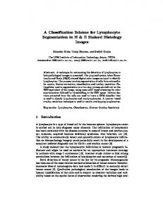
Amplifier non-linearity will be a major source of error in newer nanometer-scale CMOS technologies which have low amplifier gain and consequently offer poor amplifier linearity. Fig. 1 includes a block that models a non-linear amplifier accurately using a non-linear polynomial expression according to (5): Vout (i ) V ' out (i ) 1 � c1V ' out (i ) 2 � c 2V ' out (i ) 4 (5)
A block diagram of a 1-bit per stage pipelined ADC is illustrated in Fig. 1. For a switched-capacitor implementation of the pipeline stages [1], the output residue voltage of pipeline stage i, Vout(i), can be expressed according to equation (1) below. Non-idealities such as finite op-amp gain coefficient K, capacitor mismatch ratio r, charge injection G and non-ideal reference voltage Vref(i) are included (see Fig. 1).
�
Fig. 1. Pipelined 1-bit per stage ADC K (1 � r )V out (i � 1) � KrD (i)V ref (i) � G
V ' out (i )
K
Ao , where Ao is the finite op-amp gain. C 1 � 1 � Ao C2
Simulations for a 14-bit pipelined ADC show that 1% nonlinearity can cause differential non-linearity errors of more than 100 LSBs. Calibration for the errors caused by the nonlinearity modeled by (5) will be covered in section IV and is one of the highlights of the proposed calibration scheme. Comparator offsets are corrected through redundancy and therefore have not been used in the modeling of the pipeline in this paper. Charge injection is eliminated through bottom plate sampling [1]. Errors in voltage references is another source of distortion in high-speed, high resolution pipelined ADCs. Inductive coupling and bond-wire inductance causes ringing at high frequencies in voltage reference lines. This is a serious error that will cause distortion in the ADC output and is difficult to correct for. Traditionally, a large off-chip capacitor is used to stabilize the reference voltages. This may not always be feasible in embedded system-on-chip design, where the number of pins available for external compensation is limited. One solution to this problem is to insert analog buffers for every pipeline stage and eliminate the need for additional compensation capacitors and stabilizing circuitry without too much area and power overhead. This will isolate each pipeline stages from each other and prevent coupling between them. Each buffer can be optimized for the load seen to guarantee settling for the given speed specifications and consequently save power consumption. However, due to mismatch, offsets and different load impedance seen by each buffer, the reference voltages provided to each stage may be different from each other. This will be a source of static distortion, rather than a dynamic distortion, and can be easily corrected by the proposed calibration scheme. This paper proposes a calibration scheme in section IV to correct for static errors caused by these reference voltage mismatches between stages and is another highlight of the proposed scheme.
(1)
If we apply (1) recursively from the last stage in an N-stage pipeline to the first we will obtain (2). For illustration purposes, all non-idealities are set equal for all stages without loss of generality. Non-linearity is omitted in (2) and will be covered in subsequent sections. N § rV · VN G ref (i ) ¸ (2) ¨ Vin D (i ) � i � N N i �1 i i ¸ ¨ K (1 � r ) (1 � r ) K (1 � r ) ¹ i 1 ©K Neglecting the first term, we get the expression for the input signal in terms of the digital output bits: N rV ref (i ) Vin # D(i ) � G (3) i �1 (1 � r ) i i 1 K
¦
¦
By setting K=1, r=1, G=0 and Vref(i)=Vref for all i, the ideal expression for the input in terms of the digital output bits is obtained: N V ref Vin D(i ) (4) i i 1 2
IV.
DIGITAL ERROR CORRECTION CALIBRATION SCHEME
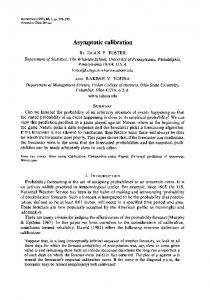
The basic idea behind the error correction scheme (see Fig. 2) is to correct for the residue errors in the non-ideal pipeline stages by using a suitable set of parameters (error correction block in Fig. 2), which are determined by comparing the digital output of the ADC with the digital output of a slow, low power high resolution reference ADC. Such an ADC could be a Sigma-Delta Converter with a high over sampling ratio (OSR) running at speeds much lower than the main ADC, offering the speed-power-accuracy tradeoff in its design. See Fig. 2. for illustration at block level of the calibration setup.
¦
III. SOURCES OF ERRORS IN PIPELINED ADCS From equation (3) we observe that the major sources of errors in pipelined ADCs are finite amplifier gain (Kz1), capacitor ratio mismatch (rz1) and charge injection (Gz0). Finite amplifier gain will create an incorrect residue output according to (1) but it will allow lower power consumption. However, this will likely also reduce the linearity of the amplifier which will introduce distortions in the ADC output.
38
this amplifier. However, as mentioned in section II, reducing the gain will likely introduce non-linearity, and consequently requiring nonlinear calibration. The output of stage 1, Vout(1), is digitized by the back-end of the pipeline and Dout,2..N , can be viewed as the digital equivalent of the output residue when linear calibration parameters are used to correct for non-idealities according to (7). The non-linearity is then corrected for according to (10). The non-linearity would be completely cancelled if the last two terms in equation (5) were added to the digital output with opposite signs. However, the solution of (5) as a function of Vout(1) is not possible in digital domain. Instead, Vout(1) will be used to approximate V’out (1). The final digital output is expressed according to (10) in order to correct for nonlinearity:
Fig. 2. Block diagram of calibration setup The error correction scheme involves two steps. The first step is to estimate the correction parameters using a LeastMean-Squares (LMS) algorithm. We start by observing that equation (4) can be normalized by the reference voltage to get the digital equivalent of the input: N
Dout ,ideal
¦ i 1
D(i ) 2i
Dout
(6)
N
¦ i 1
b(i ) D (i ) 2
a1 _ new
The technique proposed above is an extension of the technique proposed for calibration of just finite op-amp gain and capacitor ratio mismatch [6]. For our case, a pipeline with N non-ideal stages will require N parameters to correct for errors. But in practical implementations, for a given technology and design, it may be enough to calibrate the first few pipeline stages, and hence will require less than N parameters for calibration of the entire ADC. The digital output of the main ADC is processed in digital domain to incorporate the estimation parameters b(i). The slow, low power ADC connected in parallel is used to generate the ideal digital output Dideal for the same input. The following Least-Mean-Squares (LMS) algorithm is then used to estimate the coefficient b(i):
b(i ) new
b(i ) old
wH 2 , where H �P wb(i )
Dideal � Dout
a1 _ old � P ' ' HDout , 2.. N
3
(11)
P” is the update step-size. It can be shown that for a monotonic non-linear function in (5), a1 can be accurately estimated using the update equation (11). The second step in the calibration scheme is to process the raw digital output of the non-ideal ADC using the estimated correction parameters b(i) and a1 according to (7) and (10) respectively. Thus, we have shown that a set of correction parameters estimated adaptively using a slow high resolution ADC can be used for calibration of non-idealities including op-amp non-linearity.
(7)
i
(10)
For many practical cases, the term to the power of three, a1 will dominate and in this paper only this term is estimated for correction. The calibration parameter a1 is updated by an LMS algorithm according to (11):
By comparing equations (3) and (4) we find that the digital output deviates from the ideal due to non-idealities and hence must be modified to correct for errors. Therefore, the problem of calibration becomes that of estimating b(i) in the following expression: Dout
3 5 Dout � a1Dout , 2.. N � a2 Dout , 2.. N
V. DESIGN CONSIDERATIONS Parameter estimation can be performed in the background during normal conversion operation. Since the parameters change only slowly with time, the calibration algorithm can be run only once in every few thousand cycles. This enables the use of a low power, high resolution ADC where speed has been traded-off for accuracy. The sigma-delta converter is inherently insensitive to mismatches and can be implemented with low-gain amplifiers and without the need for selfcalibrating circuitry. In the proposed calibration scheme, during parameter estimation, the sigma-delta converter digitizes every one 1 out of M input samples to the main ADC (see Fig. 2). The number of clock-cycles required by the sigma-delta converter to generate an ideal estimate of the input is a function of its OSR and the resolution of the main ADC. For our application, a very high OSR (greater than 128) was used, since the speed of parameter estimation is not an issue. Another choice of architecture could be an algorithmic ADC with a slow, high-gain op-amp but it will require selfcalibration for capacitor mismatch [8]. The whole algorithm is performed in digital domain with few parameters (small memory), few multiplications and additions. The
(8)
For ease of implementation and to avoid multipliers, a modified sign-sign version of the LMS algorithm can be used [11]: b(i ) new b(i ) old � P ' sign(H ) sign( D(i )) (9)
P’ is the update step-size for the LMS algorithm and can be made programmable for faster conversion [11]. The above correction algorithm will correct for all linear static errors in the pipeline presented in section I. Correction of non-linearity given by (5) is performed only for the first stage in the pipeline, which has the highest resolution requirements. The amplifier in the first stage usually consumes more power than the amplifiers in other stages, and significant reduction in power consumption can be achieved by reducing the gain of 39
multiplications can be easily performed with shift registers if the correction parameters are represented as a power of 2 due to the pipelined nature of the output. However, one drawback of this scheme is that the computation of the cube of the digital output has to be performed at the rate of conversion. However, since pipelined ADCs are used in applications where latency is not a big concern, a high throughput, high latency, pipelined and retimed multiplier can be used [12],[13].
case where non-linearity is present but only linear calibration parameters are used is also presented for comparison to appreciate the need for nonlinear calibration. The results indicate that linear calibration parameters cannot restore the output completely and there is significant distortion due to amplifier nonlinearity. VII. CONCLUSION A technique to correct for static linear and non-linear errors in pipelined ADCs with a digital background calibration scheme is presented. The technique shows promise for lowvoltage, ultra-high-speed ADC designs where reference voltage mismatch due to buffer insertion in reference path and amplifier non-linearity’s will become a major source of distortion. This is especially true for ADCs designed in deep sub-micron and nanometer scale CMOS technologies. Simulations performed showed several orders of magnitude improvement in the linearity of the converter before and after calibration.
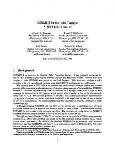
VI. SIMULATION RESULTS A 14-bit pipeline ADC has been simulated in MATLAB for illustration purposes. There are ten extra stages in the pipeline. It is assumed for simplicity and illustration purposes that stage 6 onwards have the same non-idealities, so only one parameter is required to calibrate for those stages. Op-amp gain is as low as 60 dB, capacitor mismatch ratio is as high as 0.5%, reference voltage errors varies up to 1% and the maximum non-linearity is 1%. The output power spectrum of the main ADC with non-idealities present is shown in Fig. 3. The output with and without calibration is presented:
REFERENCES [1] [2] [3] [4]
[5]
[6]
Fig. 3. Output Power Spectrum. a) Before Correction b) After Correction
[7]
The performance of the ADC before and after the proposed calibration scheme, with and without amplifier non-linearity (NL) present, is summarized in table I.
[8]
[9]
Table I. ADC performance before and after calibration SFDR SNDR INL DNL (dB) (dB) (LSBs) (LSBs) Corr. with NL 96.5 80.2 1 0.45 Uncorr. with NL 49.9 47.7 70 132 Corr. without NL 97.1 80.0 1.2 0.8 Uncorr. without NL 55.3 52.7 41 71 Corr. - only linear 65.8 62.4 6 5 cal. param. with NL.
[10] [11] [12] [13]
Simulations show that the Spurious-free-dynamic-range (SFDR) is increased from 49.9 dB for the un-calibrated case to 96.5 dB after calibration. Signal-to-Noise-and-Distortionratio (SNDR) is increased from 47.7 dB to 80.2 dB for the pipelined ADC. The linearity of the ADC is improved and the integral non-linearity (INL) and differential non-linearity (DNL) are reduced below 1 LSB after calibration. Another
40
M. Gustavsson. CMOS Data Converters for Communications. Kluwer Academic Publishers, 2000. Un-Ku Moon; B.S. Song. Background digital calibration techniques for pipelined ADCs. IEEE CAS-II, 44(2):102-109, Feb. 1997. S. U. Kwak, B. S. Song, and K. Barcania, “A 15-b 5-Msample/s Lowspurious CMOS ADC,” IEEE JSSC, 32(12): 1866-1875, Dec. 1997. J. Ming; S.H. Lewis. An 8-bit 80-Msample/s pipelined analog-to-digital converter with background calibration. IEEE JSSC, 36(10): 1489-1497, Oct. 2001. J. Ingino, and B. Wooley, A continuously calibrated 12-b analog-todigital converter with on-chip precision trimming, IEEE JSSC, 33(12): 1920-1931, Dec. 1998. S.R. Sonkusale, J. Van der Spiegel, K. Nagaraj. Background digital error correction for pipelined Analog-Digital Converters. IEEE CAS 2001, pp. 408-411, May 2001. Y. Chiu, C.W. Tsang, B. Nikolic, P.R Gray. Least Mean Square Adaptive Digital Background Calibration of Pipelined Analog-to-Digital Converters. IEEE CAS-I, 51(1):38-41, Jan. 2004. X. Wang, P.J. Hurst, S.H Lewis. A 12-bit 20-MS/s pipelined ADC with nested digital background calibration. IEEE CICC, 409-4712, Sept. 2003. S.R. Sonkusale, J. Van der Spiegel. Mixed-signal calibration of pipelined analog-digital converters. IEEE SOC, 327-330, Sept. 2003. B. Murmann, B.E. Boser. A 12-bit 75-MS/s pipelined ADC using openloop residue amplification. IEEE JSSC, 38(12): 2040-2050, Dec. 2003 S. Haykin. Adaptive Filter Theory. Prentice Hall, Upper Saddle River, 1986. K.K Parhi, VLSI Digital Signal Processing Systems : Design and Implementation. John Wiley & Sons, 1999 R.J. Hartley, K.K Parhi. Digit-Serial Computation. Kluwer Academic Publishers, 1995.