S.-H. Hong et al.: A Base-station Centric Data Gathering Routing Protocol in Sensor Networks Useful in Home Automation Applications
945
A Base-station Centric Data Gathering Routing Protocol in Sensor Networks Useful in Home Automation Applications Sung-Hwa Hong, Byongguk Kim, and Doo-Seop Eom Abstract — In the future ubiquitous home network, sensors will collect various home environment data in the home. Since the sensor nodes are equipped with small, often irreplaceable, batteries with limited power capacity, it is essential that the network be energy-efficient in order to maximize its lifetime. Our study, described in this paper, was divided into two classes: the primary class was to set a power-based level and the secondary class was to propose an offer of a home automation using a routing technique centered on a sensor network to set a flooding level. The proposed scheme divides the home into areas such as rooms and locates the WENs in each area. The WENs collect data from sensors and deliver the data to the home base station only. Sensors deliver the data to the WENs or the home base station through the sensor with the stronger power. Performance results show that the proposed scheme is more efficient with a wireless home network 1. Index Terms — Home Network, Wireless Sensor Networks, Sensor Routing, Home Automation, Zigbee.
I. INTRODUCTION With the rapid advance in semiconductor production and communications technologies, the variety of consumer electronics used at home has been and continues to become digital. Developers of these digital home appliances have pursued providing their users with better services in the manner of interworking based on data communications, rather than having these devices operate independently. In this context, home networking plays a key role in these evolutionary processes. Wireless home networking is coming into the spotlight, as a consequence of the inconvenience of in-home hard wiring, and the convenience of wireless’ innate mobility, in spite of the presence of several proposed homenetworking techniques. Technologies intended to implement wireless home networking include: IEEE 802.11 wireless local area network (LAN), Bluetooth, IEEE 1394, UWB(Ultra WideBand)-based wireless network, and ZigBee used primarily to control all kinds of home appliances. Currently, there are several ongoing studies on ubiquitous sensor networks for context-aware-based home services. However, we expect that wireless home networking based on the IEEE 1 This research was partially supported by University IT Research Center (ITRC) Project and Brain Korea (BK) 21 Project. The authors are with the Dep. of Electronics and Computer Engineering, Korea University, Seoul, Korea. (email:
[email protected] ; {dearbk, eomds}@final.korea.ac.kr)
Contributed Paper Manuscript received July 14, 2007
802.11 wireless LAN and Bluetooth, which have been adopted almost universally due to their technical maturity, will be predominant in the foreseeable future. IEEE 802.15.4, considered mainly for sensor networks, is unfit to transmit high-capacity data. Thus, this technology is fit for home automation, while the conventional wireless LAN technology is suitable for multimedia services. Sensor networks complying with IEEE 802.15.4 will enable service users to access data or information whenever and wherever. In addition, routing transmission techniques using such a sensor have been sought in multilateral ways. Unfortunately, however, almost all of the efforts made to do so have been aimed primarily in improving data transmission and sensor durability, rather than in controlling sensors required for home networking and finding the exact locations of them. Accordingly, in this study, a node functioning as a sort of gateway was placed in each room by using IEEE 802.15.4 so that it could control all sensor nodes within its own domain and transmit data to the Base Station (AP) set up in consideration of future integration with a wireless LAN. At this juncture, relay nodes were installed between the gateway node and AP to ensure effective data transmission. For wireless sensor networks [1]-[2], attribute-based addressing rather than global addressing is more appropriate. Since query characteristics generated in sensor works concern mostly attributes, attribute-based addressing is necessary. Thus, broadcasting or multicasting rather than point-to-point communications is more suitable. In addition, data collected from sensor nodes is delivered to the user requesting it, by any of the various external media such as the Internet or artificial satellite which are connected with nodes called sink nodes. At this time, data aggregation is required to save wasted energy attributed to redundant transmission of similar information among adjacent nodes in the process of delivering collected data. Examining the characteristics above, a cluster-based hierarchical routing algorithm seems ideal for wireless home automation. This algorithm has several merits for sensor networks. As described previously, it ensures more energyefficient routing in the manner of forming local clusters and transmitting the information on events incurred in an adjacent area to the gateway nodes, followed by data aggregation by means of the gateway nodes. This algorithm also prevents inefficient query flooding through delivery to the gateway node for the requested query. To improve energy efficiency at the network layer, inefficient routing should be reduced and instead, power control for sensor nodes can be added. It is possible to
0098 3063/07/$20.00 © 2007 IEEE
IEEE Transactions on Consumer Electronics, Vol. 53, No. 3, AUGUST 2007
946
improve significantly energy efficiency by controlling sensor nodes to prevent them from being involving in transmission, e.g., in sleep mode, with powering off their transceivers, although this technique is applicable to some kinds of applications only. Similarly, the technique of powering off transceivers except for a data transmission cycle and receipt cycle is used at the MAC (media access control) layer as well. At the MAC layer, however, any information on networks is insufficient and if necessary, it takes some time to power on and off transceivers leading inevitably to delayed transmission. Since it is feasible to obtain information on the networks controlling transceiver power above the network layer, the power can be controlled with separation between some nodes where it is possible to transmit data to sink nodes and the other nodes where it is impossible to do so. As mentioned above, as it is possible to power off nodes not involved in transmission depending on the applications, its combination with a MAC layer protocol can enable it to achieve a more significant energy-saving effect. We present a new sensor routing scheme that provides data delivery from sensors to a home base station. The proposed scheme divides the home into areas such as rooms and locates the relay nodes to each area. The relay nodes collect the data from sensors and deliver the data to the home base station only. Sensors deliver the data to the relay nodes or the home base station through the sensor with the stronger power. In Section II, we describe related works. In Section III, we describe our system model, and in Section IV, we present detailed operation of the proposed algorithm. Finally, we give concluding remarks in Section V. II. RELATED WORKS Supporting the mobility of sensor nodes is one of the most important factors to enable ubiquitous sensor networks, since mobile wireless sensor nodes can be attached to the human body, vehicles, and other mobile objects. So, the network layer should be implemented with the viewpoint of an efficient routing algorithm for wireless mobile sensor nodes [6]-[9]. To efficiently maintain the routing path between a sink node and sensor nodes, various routing algorithms have been proposed. The hierarchical routing algorithm is one of them. Typical hierarchical routing algorithms are LEACH and LEACH-C. Direct communication is the simplest and the most intuitive way to send and collect sensor data. In a direct connection, each sensor sends data to the base station directly. It is simple, but may consume a large amount of energy for nodes further away from the base station. Based on the first order radio model, the energy drains more rapidly as the distance from the base station grows. Low-Energy Adaptive Clustering Hierarchy (LEACH) [3] divides the entire network into clusters. Each cluster has a cluster head. Nodes in each cluster send their data to the
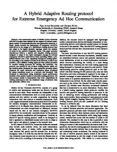
cluster head. The cluster head then collects the data and relays it to the base station. Each cluster uses different CDMA codes to avoid collisions. LEACH is a branch-based protocol, which is simple and scalable. However, this protocol is not very energy efficient for nodes. Besides, the radio of cluster heads must be turned on all the time to receive packets from the nodes in its cluster. This drains power more rapidly. In contrast to LEACH, Power-Efficient Gathering in Sensor Information Systems (PEGASIS) [4] organizes the sensor nodes by a single chain. Messages are sent hop-by-hop along the chain starting with the node farthest away from the base station. PEGASIS is often referred to as a chain-based protocol. The main advantage of PEGASIS protocol is the small total energy dissipation as nodes only need to communicate with their neighbors. However PEGASIS assumes every node has the global knowledge of the other nodes, which is not feasible. The delay also gets longer when the chain grows longer. In [5], the authors present a new centralized algorithm for constructing the minimum total energy (MTE) chain. In each step of chain construction, the algorithm searches all remaining nodes and all possible insertion positions in the chain to select a node and a corresponding position in the chain that increases the total transmission cost of the chain to the minimum amount. The node is then inserted into the chain at that position. MTE constructs the chain with a smaller total transmission energy cost than PEGASIS but has more computation complexity. III. THE SYSTEM MODEL As shown in Fig. 1, our system model consists of a gateway server, a base station, wireless sensor nodes, and wireless embedded nodes. The gateway server is the home gateway that delivers commands received from a person or out of the house to the base station in the house and controls messages received from the base station. It can be located any place in the house. The base station is an Access Point with a sensor node that has more computational ability and memory than general sensor nodes. It receives commands from the gateway and sends queries to sensor nodes. It also collects data from sensor nodes and delivers control messages to the gateway. The base station is located at the coordinate center of the house. Wireless sensor nodes have the ability to collect physical data and deliver the data to other nodes within one hop distance. Wireless embedded sensor nodes are located in some predetermined position while other sensor nodes are randomly distributed in the house. Wireless Embedded sensor nodes have external power sources, and are mounted on external devices, primarily electronics, while operating. WENs have two type: the first is the gateway node, the second is the relay node. With power levels differing depending on the type of node, the power level of the gateway node is the lowest, and that of relay node is higher than that of the gateway node.
S.-H. Hong et al.: A Base-station Centric Data Gathering Routing Protocol in Sensor Networks Useful in Home Automation Applications
to the base station via relay nodes. Second, the relay nodes transmit any data received from adjacent sensor nodes to the adjacent gateway node. Normally, sensor nodes transmit data from lower levels to higher levels to reach WENs of highlayer nodes. However, when any WEN is adjacent to sensor nodes, only if WEN functions as a gateway node, the WEN then transmits data. Otherwise, if it functions as a relay node, the sensor nodes are utilized as intermediate nodes for data transmission to the gateway node. To this end, senor nodes transmit data to the gateway node in a faster and shorter way, leading to achieving more efficient data transmission.
MN1
MN2
AP MN3
NMS (Home Gateway)
WEN(Relay node) WEN (Gateway node) Wireless Sensor node
947
Edge Router
Fig. 1 Our System Model.
IV. BCDGP — A BASE STATION CENTRIC DATA GATHERING PROTOCOL The proposed algorithm operates under the scenario described below. Indeed, sensor networks are deployed primarily centering on the gateway node and then operate. Conventional sensor networks are randomly distributed in a given area; whereas, the proposed algorithm is focused on home automation based on home networking. For the reason, it does not require random distribution of many sensor nodes. Initially, nodes are distributed. Then, with starting a power supply for sensor nodes, the nodes form hierarchical multihop networks by themselves. Here, it is assumed that all nodes within the sensor field are almost non-mobile and static nodes. Subsequently, sensor nodes respond to request queries from sink nodes. The nodes containing the requested data transmit the data to sink nodes. In this process, to improve energy efficiency, data aggregation is executed and appropriate data link layer protocols are selected for more efficient operations. A gateway node receives data transmitted from the sensor nodes within its own domain. At this moment, such sensor nodes within its own domain are called member nodes of the gateway node. The conventional clustering technique is used as the manner in which individual sensors operate. For a clustering technique, following configuring the cluster head, sensors transmit data to the cluster head. Accordingly, the cluster head consumes a considerable quantity of energy. In the event that energy falls down lower than the specified limit, the cluster formed previously by the cluster header is decomposed followed by selecting a new cluster header to form a new cluster. Thus, much energy is consumed. However, in this study, the gateway node plays this role and secures energy from the electronics that it is mounted on, so that it is possible to keep a specified level of energy constant. As a result, once any cluster has been formed, it can be preserved. Relay nodes take two actions on the member nodes of a gateway node. First, the data received from the gateway node is transmitted
A. The proposed algorithm The algorithm, we proposed in this study is characterized first by obtaining a certain desired level by using flooding in the course of detecting the first neighboring node. This algorithm then applies the resulting level to clustering, leading to very simple setup of the sensor networks. At this time, the base station, the gateway node, and the relay node are collectively referred to as the upper layer or higher layer. On the other hand, sensor nodes within the domain of a certain gateway node are collectively referred to as the lower layer. Mentioned in connection with sensor networks, the sink nodes correspond to base stations at the upper layer and gateway nodes at the lower layer. Thus, the levels to be obtained at this point are divided into twos. The first is a high-layer level, which operates only at any of the base station, the gateway nodes, and the relay nodes. These three nodes all have external power sources, and are mounted on external devices, primarily electronics, while operating. Accordingly, they are also called Wireless Embedded Nodes (WEN) whose communication distances are different from those of sensor nodes. The proposed algorithm configures only just the gateways and relay nodes with an operations preset so that they connect simply their own upper and lower levels, respectively. At this moment, because a gateway node has a shorter communication distance than that of a relay node, the former naturally belongs to the lowest level. The communication distance of a relay node is equal to or longer than that of a gateway node. Thus, the level of a relay node equals the second level obtained. Consequently, as connections to sink nodes are smoothly executed automatically via the shortest transmission path, the frequency of transmission can be reduced, resulting in higher energy efficiency. At this juncture, all of gateway nodes, relay nodes, and sink nodes are mounted on electronics during operations. Additionally, they also use external power sources during such operations, so that any internal power sources are unnecessary. With power levels differing depending on the type of node, the power level of the gateway node is the lowest, and that of relay node is higher than that of the gateway node. The second is the low-layer level process. This process is to register sensor nodes within the domain of the gateway node, as member nodes, and make a connection
948
between a wireless sensor node and a gateway node by acquiring any appropriate level. At this moment, it is assumed that communication distances among sensor nodes are the same. Thus, the level between the gateway node and sensor node is acquired through flooding. Since their own higher-layer connection only is considered, unnecessary data transmission in any directions other than the direction of the sink node is eliminated. It is possible to minimize energy consumption of more WENs compared with the usual cluster member nodes. The connection to a sink node is also ensured, leading to a highly energy-efficient protocol. What plays an important role in energy conservation of the sensor node is duration (time) control concerning whether its transceiver powers on or off. In other words, a large quantity of energy is consumed during data transmission and reception. For most energy conservation protocols at the MAC layer, any unused transceivers are powered off and only if used, powered on to reduce energy consumption. However, in such a case, it is usually inevitable to tolerate a network delay for the sake of energy conservation. Similar to MAC, routing protocols may also save energy in the manner of turning off and on transceivers. However, routing protocols do not cause any delay to occur the same as MAC. MAC turns on and off transceivers on a regular basis, while routing protocols power on and off nodes according to a given network configuration. The proposed algorithm ensures additional energy conservation as follows. B. The initial flooding process: Once a power supply starts for data transmission, a control message intended to check whether communications among neighboring sensor nodes are enabled, is delivered. For the data flow in sensor networks, a query called “interest” requesting data transmission from a sink node to sensor nodes within the domain of a gateway node is transmitted to the closest gateway node. Then, the gateway node, receiving the query, registers sensor nodes within its own domain, as its member nodes, and delivers a specified address to each sensor node. To transmit the data detected, the path from each node to the gateway node should be secured. Checking this requires receiving the minimal flooding signals originating from the sink node. In other words, it is not in doubt that any nodes failing to receive a flooding signal in this process would be isolated from neighboring nodes. To check the connectivity of sensor nodes like this, flooding is necessary. Energy consumed for any of the nodes failing to receive a signal to check only connections with their adjacent nodes and to transmit data corresponds obviously to wasted energy. However, using this flooding process, sensor nodes can check that they, themselves, are securely connected with the sink node and their operations never waste energy, as well as acquire the same level as the sink node. The nodes, receiving signals, directly from the sink node set their own levels to 1. The nodes, with their own levels of 1, contain the
IEEE Transactions on Consumer Electronics, Vol. 53, No. 3, AUGUST 2007
flooding message received from the sink node. These nodes deliver it to neighboring nodes. Of the neighboring nodes receiving it, the nodes, without their own levels of 1, then set their own levels to 2, followed by flooding to neighboring nodes again. This technique enables checking the presence of neighboring nodes through propagated levels and at the same time, securing connections with the sink node and grasping data flow. Additionally, as it is easy to set cluster gateway in line with the data flow during cluster formation. This technique can also be used for cluster control. Undergoing a series of processes described above, nodes are able to obtain useful information on their neighboring nodes. C. Flooding level Above all, once cluster formation has been completed, the flooding process is not executed. Based on the level acquired through flooding, nodes piggyback their own levels in the data transmitted to update them. This level-updating process is seen in Fig. 2.
(a)
(c)
(b)
(d)
Fig. 2 Times vs. the changes of sensor nodes.
In this figure, (a) indicates the levels of child nodes if the root (or parent) node equals level 1. This figure shows available connections between individual nodes and root or child nodes. However, in the event that the node with level 3 malfunctions, of child nodes detecting that, the node whose upstream connection has relied only on a connection with the faulty node finds out a node with the highest-layer level, i.e., with the lowest level value among its adjacent nodes. This node, then, sets its own level to the result of adding 1 to the
S.-H. Hong et al.: A Base-station Centric Data Gathering Routing Protocol in Sensor Networks Useful in Home Automation Applications
existing level. These processes are happen for a level update. The processes (a), (b), and (c) represent level-dependent data transmission from usual low-layer sensor nodes to a highlayer gateway node. The process (d) shows how to transmit data where any high-layer relay nodes are present around the sensor getting ready to transmit data. If this process is applied, even sensor nodes with low-layer lowest levels are able to transmit data at the maximal speed. D. Relations between Gateway Node and Relay Node The relations between base station and a gateway node or a relay node are similar to that between a gateway node and a sensor node. In other words, both the gateway and relay nodes transmit data to the base station. Accordingly, when flooding starts initially to find the locations of sensor nodes, the gateway and relay nodes are also subject to settings by the above-mentioned flooding level. Afterwards, the gateway node takes two actions. First, it checks any sensor nodes within its domain and, then, registers them as its member nodes. The registered sensor nodes are informed of specified address information by the gateway node where they have been registered. This enables the gateway node to control all sensor nodes within its own domain, and further, to determine whether other sensor nodes controlled by any other gateway node belong to its own domain. Similarly, the relay node also takes two actions. First, it transmits the data received from the gateway node to the base station by flooding level. At this moment, the coverage of the relay node is larger than that of the minimal gateway node. This helps the gateway node to control sensor nodes within its domain even though the sensor nodes are not interconnected. This also helps the gateway node operate independently even if individual gateway nodes are not interconnected. Second, it transmits the data received from sensor nodes within its own domain, to its adjacent gateway node. This helps sensor nodes transmit data more efficiently to the gateway node resulting in higher energy efficiency, and furthermore, to operate for a longer time by reducing the hop count.
WEN, selected by the sink node, sets its lower link only again. The lower link sets its lower link only again. The nodes, set to downstream links, record their own lower links. Afterwards, when receiving a query from the sink node, the nodes transmit the query to their lower link node. In this case, there may be just a single upper link and several lower links. At this juncture, it is important for the gateway node to use flooding levels when selecting a relay node. As assumed previously, most of the sensor nodes existing in the coverage of home network communication are almost non-mobile and static. As an example, fixed sensor nodes and a sink node feature almost a constant data flow. Sensor nodes always desire to transmit data to the sink node, while the sink node desires to inform all nodes of a data request. Therefore, when selecting a gateway node of a cluster, using a flooding level ensures that the data of a cluster is transmitted in the shortest distance in the direction of the sink node. For example, if data is not transmitted in this manner, the hop count of transmission to the sink node increases, deteriorating energy efficiency. IV. A Performance Evaluation In order to evaluate the performance of our algorithm, we simulated a routing scheme. We used NS2 and simulation programs written in the Visual-C++ programming language to evaluate the performance of our scheme. Our scheme was compared with MTE. We randomly generated networks with a diameter of 100m X 100m, each having approximately 5 to 300 nodes. We repeated the simulations for the same network, with one base station in the center, 10 times. In the case of our algorithm, the round time increased as the number of wireless embedded nodes (WENs) increased from 1 to 10. Our aim was to reduce the round times and shorten the hop counts in order to provide for the more efficient use of energy. The network dimensions for our experiments were 100m x 100m. 100 nodes were randomly generated within the region. We ran the simulations with different positions of the WENs: to the center of the field and to a place away from the region. Fig. 3 shows a simulator in a sensor field of size 100m x 100m.
E. Data transmission Once a cluster has been formed, as a rule, all of its operations are controlled by the gateway node. The information, detected and obtained in the cluster, is transmitted to the gateway node. Then, the gateway node transmits the data via data aggregation to the relay node. Next, the relay node simply transmits the data to a selected upper link. This facilitates significantly in setting upper links. Most interestingly, the upstream nodes of a cluster go towards the sink node. F. Link setting The WEN compares energy simply in selecting just a gateway node. If the quantity of energy is the same, levels are decided by a commonly used level setting process. The upper
949
Fig. 3 Our simulator program.
IEEE Transactions on Consumer Electronics, Vol. 53, No. 3, AUGUST 2007
950
As shown in Fig. 4, a node stopped gathering data because of its energy consumption. Nodes, with low energy, do not operate. Therefore, the number of nodes decreased. It seemed that the average remaining energy increased. This was because the data aggregation process did not occur in the cluster architecture. BCDGP MTE
110
105
alive Nodes
100
95
90
Most energy model parameters were similar to those in LEACH [3]. To transmit a k-bit message a distance d using LEACH’s radio mode, the radio expends: 2 ETx(k, d) = ETx−elec(k) + ETx−amp(k, d) = Eelec× k + εamp × k × d To receive this message, the radio expends: ETx ( k , d ) = E Rx − elec ( k ) = Eelec × k 2 where, Eelec = 50nJ / bit , ε amp = 100 pJ / bit / m . The simulation scenario and the parameters were as follows. Initially, 100 nodes were dispersed randomly on a 100x100m2 region and a sink node was randomly selected from the nodes. The sink node initiated the routing information setup and initial clustering. After initial clustering was finished, the sink node transmitted a query packet once every 100ms and all nodes connected to the sink node responded to the query by transmitting a data packet.
85 0
2
4
6
8
10
TABLE I THE GUARANTEE OF THE CONNECTION DEPENDED ON THE DENSITY
12
Time [s]
Density Connection
Fig. 4 Times vs. the changes of sensor nodes.
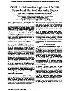
Fig. 5 shows the hop counts depending on the number of WENs and sensor nodes. As shown in Fig. 5, an increase in the number of WENs reduced the hop counts. Reducing the hop counts lead to a reduction of the remaining energy of the wireless sensor nodes. Therefore, BCDGP was the more efficient energy consumption algorithm.
0 10 20 30 40 50
7
60 2 3 4 5 6 7
5
70 80
4
en so rn od es
Hop count
6
90
80
3
2 8
6 The n umbe 4 r of W ireles 2 s Em bedd ed no des
Th en um be ro fs
60 40
100
200
225
250
275
300
2.069
1.354
1.074
0.688
0.451
3.451
2.24
0.986
0.634
0.376
2.17
1.054
0.438
0.243
0.113
1.619
0.82
0.264
0.106
0.045
1.575
0.772
0.273
0.094
0.04
1.925
0.749
0.306
0.101
0.066
2.587
1.232
0.403
0.176
0.068
4.169
1.738
0.897
0.282
0.13
8.844
5.338
2.226
1.061
0.494
24.67
21.54
10.77
7.628
5.135
46.92
63.16
82.36
88.99
93.08
20
Fig. 5 The number of sensor nodes vs. WENs vs. Hop Counts.
In this section, we report on our evaluation of the performance of the BCDGP protocol via simulations. We compared BCDGP to the MTE protocol, one of the energy efficient flat routing protocols for multi-hop sensor networks.
Table 1 can also be interpreted as an illustration of the effect of dead nodes on connectivity. As an example, when nodes with a radio range of 10m were deployed on a 0.1km2 (100x100m2) square region with a density of 200 nodes/km2, the random death of 25%(50/200) of the nodes resulted in a disconnection of roughly 55% of the nodes that were still alive, from the sink node. These nodes were useless nodes, since the information sensed by these nodes could not be delivered to the user. On the other hand, in a singe-hop
S.-H. Hong et al.: A Base-station Centric Data Gathering Routing Protocol in Sensor Networks Useful in Home Automation Applications
network, the death of one node meant elimination of only one node from the network. The above illustration explains why the balancing of energy consumption among nodes is important, especially in multi-hop sensor networks. When sensor nodes are randomly deployed, it is possible to connect nodes that have the connectivity over so many sensor nodes.
ACKNOWLEDGMENT This research was supported by the MIC(Ministry of Information and Communication), Korea, under the ITRC(Information Technology Research Center) support program supervised by the IITA(Institute of Information Technology Assessment). REFERENCES
0.16 0.14
[1]
0.12 0.10
Energy [J]
951
0.08 0.06
WEN(Gateway node) WEN(Relay node) normal total avg
0.04 0.02 0.00 -0.02 0
5
10
15
20
25
Time [s]
Fig. 6 The standard deviation of the energy depending on the class of WENs.
Figure 6 illustrates the standard deviation of the energy for depending on the class of WEN using BCDGP. The reduction of the average remaining energy of the wireless sensor nodes begins to slow down after 7 seconds. This phenomenon is due to load-balancing. V. CONCLUSION
In this paper, we proposed a new sensor routing mechanism for ubiquitous home networks called BCDGP. BCDGP provides energy efficiency in wireless sensor networks. Because it reduces the hop-counts and the round times, BCDGP is more efficient for sensor networks. BCDGP enables a more efficient data aggregation for the gateway node, resulting in a reduction in data transmission and, thus, a reduction in energy consumption. In multi-hop networks, organizing an efficient cluster structure is far more complex and energy-consuming than in single-hop networks. Thus, there is a fair possibility that cluster based approaches are less efficient than flat approaches. Our study, described in this paper, was divided into two classes: the primary class was to set a power-based level and the secondary class was to propose an offer of a home automation using a routing technique centered on a sensor network to set a flooding level. We have shown that our approach is much more efficient than the MTE protocol, one of the energy efficient flat routing protocols, with respect to average energy consumption and network lifetime. We chose a mechanism of clustering and routing that is appropriate for fixed or low-mobility networks. As a trade-off for the sake of simplicity, our algorithm is less than optimal in terms of cluster organization. Nevertheless, we have shown that our mechanism operates effectively..
I.F. Akyildiz, W. Su, Y. Sankarasubramaniam, E. Cayirci, "Wireless sensor networks: a survey," Computer Networks 38 (2002) [2] Praveen Rentala, Ravi Musunnuri, Shashidhar Gandham, Udit Saxena, "Survey on Sensor Networks" [3] W. R. Heinzelman, A. Chandrakasan, H. Balakrishnan, "EnergyEfficient Communication Protocol for Wireless Microsensor Networks" Proceedings of the Hawaii International Conference on System Science, ,page 1-10, Jan, 2000. [4] S. Lindsey and C. S. Raghavendra, "Pegasis: Power-efficient gathering in sensor information systems," in IEEE Aerospace Conference, March 2002. [5] K. Du, J. Wu, and D. Zhou, "Chain-based protocols for data broadcasting and gathering in sensor networks," in Proceedings of Workshop on Parallel and Distributed Scientic and Engineering Computing with Applications (in conjunction with IPDPS), April 2003. [6] C. Intanagonwiwat, R. Govindan, and D. Estrin, “Directed Diffusion: A Scalable and Robust Communication Paradigm for Sensor Networks,” in Proceedings of the ACM/IEEE International Conference on Mobile Computing and Networking (MOBICOM), 2000. [7] J. Kulik, W. R. Heinzelman, and H. Balakrishnan, “Negotiation-Based Protocols for Disseminating Information in Wireless Sensor Networks,” ACM Wireless Networks, vol. 8, no. 2-3, pp. 169–185, 2002. [8] K. Sohrabi, J. Gao, V. Ailawadhi, and G. J. Pottie, “Protocols for SelfOrganization of a Wireless Sensor Network,” IEEE Personal Comm. Mag., vol. 7, no. 5, Oct. 2000. [9] Z. Haas and S. Tabrizi, “On Some Challenges and Design Choices in Ad-Hoc Communications,” in IEEE MILCOM’98, October 1998. [10] Huseyin Ozgur Tan, Ibrahim Korpeoglu, "Power Efficient Data Gathering and Aggregation in Wireless Sensor Networks", ACM SIGMOD Record, Vol. 32, No. 4, Pages 66-71, December, 2003. Sung-Hwa Hong received his B.S.degree in Computer Science from Seoul, Korea University, 1996 and his M.S. degrees in Information and Communication Engineering from Hankuk Aviation University, in 2002. Since 2002, he has been in the Ph.D program in Electronics and Computer Engineering at Korea University, Seoul, Korea. His research interests include the Home Network, WLANs, adhoc networks. Byoungguk Kim received his B.S. degree in Computer Engineering from Won Kwang University, Iksan, Korea, 2002, and his M.S. degree in Electronics and Computer Engineering from Korea University, Seoul, Korea, 2004. Since 2004, he has been in the Ph.D program in Electronics and Computer Engineering at Korea University, Seoul, Korea. His research interests include Bluetooth, embedded-system, ad-hoc and sensor networking, and ubiquitous computing. Doo-Seop Eom received his B.S. and M.S. degrees in Electronics Engineering from Korea University, Seoul, Korea in 1987 and 989, respectively. In 999, he received his Ph.D. degree in Information and Computer Sciences from Osaka University, Osaka, Japan. He joined the Communication System Division, Electronics and Telecommunications Research Institute (ETRI), Korea, in 1989. From September 2000, he has been an associate professor in the Department of Electronic Engineering at Korea University. His research interests include communication network design, Bluetooth, ubiquitous networking and Internet QoS.