bility. DBTMA (Dual Busy Tone Multiple Access) [6][7], however, utilizes the exchange of RTS/CTS frames to turn on a pair of transmit and receive busy tones, ...
A BUSY-TONE BASED DIRECTIONAL MAC PROTOCOL FOR AD HOC NETWORKS Zhuochuan Huang
Chien-Chung Shen Chavalit Srisathapornphat Chaiporn Jaikaeo Department of Computer and Information Sciences University of Delaware Newark, DE 19716 {zhhuang,cshen,srisatha,jaikaeo}@cis.udel.edu
Abstract— In mobile wireless ad hoc networking environments, such as the Future Combat System (FCS), the shared wireless communication medium is an inherently limited resource and is collision prone. In this paper, we propose to adapt the Dual Busy Tone Multiple Access (DBTMA) protocol for use with directional antennas, which further increases effective channel capacity. In contrast to other directional antenna based MAC protocols, our protocol, termed DBTMA/DA, is capable of reserving channel capacity in finer grain without relying on extra locationing support. A simulation study is performed to demonstrate the better network performance of DBTMA/DA over DBTMA and the IEEE 802.11a MAC protocols.
I. I NTRODUCTION
AND
R ELATED W ORKS
In mobile wireless ad hoc networking environments, such as the Future Combat System (FCS), the shared wireless communication channel is an inherently limited resource and is collision prone. Furthermore, the lack of infrastructure in ad hoc networks makes it harder to design effective MAC mechanisms that adapt to dynamicity in network topology and traffic condition in addition to efficiently sharing the communication channel. The CSMA protocol, when applied to wireless ad hoc networks, causes the hidden terminal and the exposed terminal problems [1]. MACA (Medium Access Collision Avoidance) [2] relieves these problems by leveraging the RTS/CTS (Request-To-Send/Clear-To-Send) scheme. MACAW [3] refines MACA by introducing an RTSCTS-DS-DATA-ACK message exchange and a new backoff algorithm. FAMA (Floor Acquisition Multiple Access) [4] combines non-persistent carrier sensing and the RTS/CTS scheme together such that collision avoidance is performed at both the receiver and the sender. The IEEE 802.11a MAC [5] is a variation of CSMA/CA (CSMA with Prepared through collaborative participation in the Communications and Networks Consortium sponsored by the U. S. Army Research Laboratory under the Collaborative Technology Alliance Program, Cooperative Agreement DAAD19-01-2-0011. The U. S. Government is authorized to reproduce and distribute reprints for Government purposes notwithstanding any copyright notation thereon.
Collision Avoidance) protocol that supports both physical (CSMA) and virtual (RTS/CTS scheme) carrier sensing. In addition, it uses positive acknowledgment to improve reliability. DBTMA (Dual Busy Tone Multiple Access) [6][7], however, utilizes the exchange of RTS/CTS frames to turn on a pair of transmit and receive busy tones, which jointly reserve the data channel. The MAC protocols stated above all assume the usage of omnidirectional antennas. Directional antennas, however, are capable of transmitting/receiving only in certain narrow azimuth and thus significantly increases the channel capacity and reduces the possibility of collision. In [8], electrically steerable adaptive antennas are shown to improve performance on a slotted ALOHA network. In [9] and [10], MAC protocols using tones on separate channels as well as directional antennas are proposed to minimize the transmission interference. Recently, [11] applies directional antennas to the IEEE 802.11a MAC protocol by sending the RTS, data, and ACK frames directionally and succeeds in achieving better network throughput. However, it relies on accurate tracking and locationing technology, such as GPS or periodic location beaconing. [12] avoids this problem by exchanging omnidirectional RTS/CTS frames between neighboring nodes in order for them to recognize the direction of each other. However, it loses the benefits of reduced transmission area and increased channel capacity associated with directional RTS frame. In this paper, we proposed a MAC protocol that adapts DBTMA for use with directional antennas. By transmitting busy tones directionally, in addition to the directional transmission of RTS/CTS and data frames, it avoids collisions in a much finer grain in terms of spatial reuse and thus increases the channel capacity significantly. We also studied and compared the effects of directional versus omnidirectional busy tones on network performance. The remainder of this paper is organized as follows. Section II reviews the key concepts in wireless MAC protocols and briefly contrasts these MAC protocols with special interest in their ability to solve the hidden terminal and the exposed terminal problems. Section III presents
our proposed DBTMA/DA protocol and analyzes its variant schemes. Section IV presents simulation results that compares DBTMA/DA with DBTMA and the IEEE 802.11a MAC protocol. Section V concludes this paper. II. P RELIMINARIES
AND
OVERVIEW
A. Hidden and Exposed Terminal Problems Due to the path loss property of wireless communication, nodes that do not hear each other’s transmission may collide in their transmissions, while nodes that hear each other’s transmission may not collide in their transmissions. Consequently, naive usage of CSMA in wireless networks causes the so-called hidden terminal and exposed terminal problems. B. Generic RTS/CTS Scheme The generic RTS/CTS scheme operates as follows. When a node A has data to send out, it first sends RTS frame to the intended receiver node B. Upon receiving the RTS frame, node B replies a CTS frame back to node A. If node A successfully receives the CTS frame, it starts sending out data frame; or it backs off for an increasing period of time and tries again. C. Omnidirectional RTS/CTS MAC Protocols In the IEEE 802.11a MAC protocol, when the virtual carrier sensing [5] is enabled, in addition to enacting the generic RTS/CTS scheme, a node that overhears an RTS frame defers for the CTS frame and the corresponding data frame to transmit, while a node that overhears the CTS frame defers for the corresponding data frame to transmit. In summary, all nodes within the transmission range of either the sender or receiver are denied transmitting and receiving during the data transmission. Therefore, the hidden terminal problem is relieved, while the exposed terminal problem is not. In MACA, MACAW and FAMA, however, a node that overhears an RTS frame only defers for the corresponding CTS frame to transmit. The consequence is that the exposed terminal problem, in addition to the hidden terminal problem, is also relieved. DBTMA is distinguished from the MAC protocols described above in that it does not explicitly force the recipients of the RTS/CTS frames to defer. Instead, it uses the RTS and CTS frames to turn on transmit and receive busy tones until the data transmission is completed. A node that hears transmit/receive busy tone will defer receiving/transmitting, which resolves both the hidden and the exposed terminal problems.
D. Directional RTS/CTS MAC Protocols [11]∗ adapts the IEEE 802.11a MAC protocol by sending the RTS and data frame directionally. Besides inheriting the benefit of relieving the hidden terminal problem, it also relieves the exposed terminal problem as well as expands channel capacity, attributed to using directional antennas. E. Problem of the RTS/CTS scheme MACA/PR [13] presented a scenario in which the RTS/CTS scheme fails to solve the hidden terminal problem. The fundamental reason for the failure is that the RTS/CTS scheme relies on the successful and timely delivery of the RTS/CTS frames. With the significant dynamicity in network topology and traffic condition in ad hoc networks, collisions involving the RTS/CTS frames are frequent, which increase the chance of the hidden terminal problem. In summary, all MAC protocols mentioned above, except DBTMA, depend directly on the RTS/CTS frames to relieve the hidden terminal problem and may fail in case of the collision of the CTS frames. DBTMA, however, effectively prevents such problem by utilizing busy tones, which are long-lasting and collision-free signal for reserving channel capacity, as compared to the short and collision-prone RTS/CTS frames. III. DBTMA/DA: DBTMA P ROTOCOL U SING D IRECTIONAL A NTENNA A. DBTMA Protocol In DBTMA, a single channel is split into two sub-channels: a data channel for data frames and a control channel for control frames. In addition, two busy tones, transmit busy tone (BTt) and receive busy tone (BTr), are assigned two separate single frequencies in the control channel. A node that is transmitting/receiving data turns on BTt/BTr, which can be heard by all nodes within its transmission range. By using the dual busy tones, DBTMA reserves the channel in both directions, which distinguishes itself from other wireless MAC protocols. The protocol operates as follows. When a sender has data ready, it first senses the channel for BTr to make sure that the intended receiver is not currently receiving from another “hidden” node. If BTr is not present, the sender transmits a RTS frame to the intended receiver. Upon receiving this RTS frame, the receiver senses for BTt to make sure that the ∗
In that paper, two schemes are presented. Since they are very similar in design and performance, for simplicity, we only consider ‘Scheme 1’, which only uses directional RTS frame.
data it is expected to receive will not collide with another ongoing data transmission nearby. If BTt is not present, it replies with a CTS frame and turns on BTr until data is completely received. Upon receiving the CTS frame from the intended receiver, the sender begins data transmission and turns on BTt until data transmission is completed. B. Directional Antenna Model
strongest gain for a received frame. Our protocol relies on similar antenna support for neighboring nodes to learn their relative directions. The difference is that ours transmits directional CTS instead of omnidirectional CTS frame. 2) Finite State Machine: The finite state machine (FSM) of DBTMA/DA is illustrated in Figure 2 and Table I. As in DBTMA [6] and MACAW [3], we use MILD (Multiple Increase Linear Decrease) as the backoff algorithm.
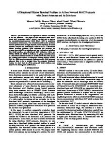
We adopted the switched beam directional antenna [14] model as depicted in Figure 1, which is similar to what is used in [12]. Each node is equipped with a directional antenna that consists N antenna elements deployed into fixed sectors each spanning an angle of (360/N ) ◦ . When transmitting, the signal will be propagated in exactly one or all of the sectors, which correspond to unicast and broadcast, respectively. Signals will be sensed in all sectors and the antenna is capable of recognizing the sector with the maximum gain. Therefore, when receiving, exactly one sector, which usually is chosen by the sensing process, will collect the signals.
CONTEND
4
1
2
3
WF_CTS
6
5
8 IDLE
WF_DATA
9
7
TRANSMIT
Fig. 2. Finite State Machine of DBTMA/DA
TABLE I T RANSITIONS IN F INITE S TATE M ACHINE OF DBTMA/DA
(a) Unicast
(b) Broadcast
ID 1 2
Fig. 1. Top-view of ideal N -sector antenna pattern(N = 8)
Though the node may be mobile, we assume that the orientation of each sector will remain fixed. We adopt an ideal azimuth antenna pattern for directional antenna, which has the same transmission range as omnidirectional antennas. In other words, omnidirectional antenna azimuth pattern is a summation of that of directional antenna elements in all directions, which is also assumed in [11] and [12].
3
4
5
CTS is received from intended data receiver
6 7
RTS timer times out data transmission timer times out
8
RTS is received AND BTt can not be heard in any direction
9
data transmission is completed OR CTS timer times out
C. DBTMA/DA Protocol 1) Applying Directional Antennas: In order to improve channel capacity, we modified the original DBTMA by transmitting RTS/CTS frames, data frame, and the dual busy tones directionally. One fundamental requirement of applying directional antennas is “direction locationing,” with which a node can select an antenna element in the intended direction. This problem is addressed in [11] by relying on GPS or beaconing messages. However, this solution suffers from inaccuracy due to hardware capability and has the drawback of soft-state schemes, especially in a highly mobile environment. This issue is tackled in [12] via omnidirectional exchange of RTS and CTS frames between neighboring nodes in order for them to learn each others’ relative direction, by selecting the direction with the
Trigger has data ready contention timer times out AND BTr can be heard in some direction contention timer times out AND BTr can not be heard in any direction RTS is received AND BTt can not be heard in any direction
Operation set contention timer backoff
send RTS to the intended data receiver in all directions; start RTS timer cancel contention timer; send CTS back to the RTS sender in the direction towards the RTS sender; start CTS timer; turn on BTr in the direction towards the RTS sender (or in all directions) turn on BTt in the direction towards intended data receiver (or in all directions) backoff turn off BTt in the direction towards the intended data receiver (or in all directions) send CTS back to the RTS sender in the direction towards the RTS sender; start CTS timer; turn on BTr in the direction towards the RTS sender (or in all directions) turn off BTr in the direction towards the data sender (or in all directions)
3) Omnidirectional vs. Directional Busy Tones: By using directional antennas, data transmissions may not collide
with each other as when omnidirectional antennas are used otherwise. For example, in Figure 3 ∗ (b), when omnidirectional antenna is used for data transmission, node F could not transmit data to node E while node A is transmitting data to node B. Similarly, in Figure 4 ∗ (a), node C could not transmit data to node D while node A is transmitting data to node B. The result is that more data transmissions could exist simultaneously within the same space, and thus channel capacity is expanded. However, assuming busy tones are turned on omnidirectionally, the original DBTMA can not enable such simultaneous data transmissions even though data is transmitted directionally. We propose to address the problem by using directional busy tones. As presented in Table I, each of the dual busy tones could be turned on directionally or omnidirectionally. Therefore, there are four possible combinations of the dual busy tones. We term them as scheme DD, OD (Omnidirectional BTt and Directional BTr), DO and OO (Note that OO is different from DBTMA in that CTS and data frames are transmitted using directional antennas.)
F E
E A
B
(a) Omnidirectional BTt
A
B
(b) Directional BTt
Fig. 3. Omnidirectional vs. Directional BTt (Directional BTr)
D’, it would collide with data transmission from node A to node B. Since the probability for C to transmit data to a D’like node is much less than a D-like node with the increase of the number of antenna elements, the overall performance will still be improved. In the meantime, it is easy to deduce that scheme OD is inferior to scheme DD. Therefore, in general, it is expected that performance is better when both busy tones are turned on directionally, which is evidenced by our simulation study below. IV. P ERFORMANCE E VALUATION A. Simulation Environment The simulations are conducted using QualNet [15] 3.1, which supports directional antenna at receiving side. We extend its models in the physical and radio (antenna) layer to support directional antenna at the transmitting side as well. We adopt the switched beam antenna in our simulation, and model directional antenna pattern as described in Section III-B. The channel-split is implemented by configuring two set of physical models, both using IEEE 802.11b PHY specification, with independent set of parameters. The narrow bands used by single-frequency sine waves for busy tones are considered negligible. We choose AODV (Ad hoc On-demand Distance Vector) [16] as the routing protocol, and use CBR (Constant Bit Rate) flows with different packet arrival interval to model varied traffic load. The set of parameters chosen is listed in Table II. TABLE II
D A
B
C
(a) Omnidirectional BTr
D C A
B
D’
(b) Directional BTr
Fig. 4. Omnidirectional vs. Directional BTr (Omnidirectional BTt)
It may seem at a first glance that directional antenna based solutions always perform better than omnidirectional ones. However, tradeoff exists between these alternatives. Figure 3 reveals the benefit of using directional BTt. When BTt is turned on using directional antenna, data transmission from node F to node E is allowed when node A is transmitting to node B, since node E can not hear A’s BTt. Figure 4 reveals the tradeoff of using directional BTr. When BTr is turned on using directional antenna, data transmission from node C to node D is allowed when node A is transmitting to node B, since node C can not hear B’s BTr. However, node C is also allowed to transmit data to node ∗
In the figure the directional antenna has four sectors.
PARAMETERS USED IN SIMULATION Parameter Grid Unit Propagation Pathloss Model Channel Data Rate Data Transmission Power Power Range Sensing Threshold Receiving Threshold Antenna Model Number of Directional Antennas Packet Size CBR Packet Arrival Interval Simulation Time
Value 240 m Two ray 2.0 Mbps 7.87 dBm 250.0 m -91.0 dBm -81.0 dBm Switched beam 8 512 Byte 1 ms - 500 ms 300,000 ms
B. Results and Discussion We evaluate a 6x6 mesh topology as illustrated in Figure 5. The grid unit is the distance between two adjacent nodes. We use two application layer metrics, throughput and endto-end delay, to evaluate DBTMA, the IEEE 802.11a MAC, and the four schemes of our DBTMA/DA protocol. We
12
18
24
30
36
5
11
17
23
29
35
4
10
16
22
28
34
3
9
15
21
27
33
2
8
14
20
26
32
Comparison in Throughput (node 15 to node 21) 1000
800
Throughput (kbps)
6
600
400
200
DBTMA DBTMA/DA_DD DBTMA/DA_DO DBTMA/DA_OD DBTMA/DA_OO 80211
0 0
1
7
13
19
25
500
1000
1500
31
2000 2500 Traffic load (kbps)
3000
3500
4000
4500
Fig. 6. Throughput of node 15 to node 21 Fig. 5. Mesh Topology (6 X 6) Comparison in Throughput (node 22 to node 16) 1000
We first consider a simple scenario that consists of two CBR flows: one flow is from node 15 to node 21; the other flow is from node 22 to node 16. The results for this scenario are illustrated in Figures 6 through 9. Figures 6 and 7 shows that when the network is saturated, scheme DD has almost twice as much throughput as others. The reason is that directional busy tones will not block unintended transmitter/receivers. In particular, node 15 only turns on BTt in the direction towards node 21 and thus will not block node 16 from receiving from node 22. If the BTt were turned on omnidirectionally, node 16 would be blocked from receiving. In the meantime, node 21 only turns on BTr in the direction towards node 15 and thus will not block node 22 from transmitting to node 16. If the BTr were turned on omnidirectionally, node 22 would be blocked from transmitting. In order for node 22 to transmit to node 16 while node 15 is transmitting to node 21, neither node 16 nor node 22 can be blocked. This explains the reason why the other three schemes of DBTMA/DA have the similar throughput as DBTMA, since each of them uses at least one omnidirectional busy tone, which blocks unintended transmitter/receiver. Meanwhile, the less time a node is blocked from receiving/transmitting a frame, the less the overall end-to-end delay, as evidenced by Figures 8 and 9. We further experiment on a complicated scenario that consists of 12 interleaved five-hop CBR flows (1 → 31), (2 → 32), (3 → 33), (4 → 34), (5 → 35), (6 → 36); (1 → 6), (7 → 12), (13 → 18), (19 → 24), (25 → 30) and (31 → 36). The results are illustrated in Figure 10 and Figure 11, It can be easily observed that scheme DD has the best throughput and remarkably better end-to-end
800
Throughput (kbps)
vary the packet arrival interval of these CBR flows in order to observe how these MAC protocols react to the dynamicity in the traffic load.
600
400
200
DBTMA DBTMA/DA_DD DBTMA/DA_DO DBTMA/DA_OD DBTMA/DA_OO 80211
0 0
500
1000
1500
2000 2500 Traffic load (kbps)
3000
3500
4000
4500
Fig. 7. Throughput of node 22 to node 16
delay, especially when the network is saturated. In particular, contrasting scheme DD and the IEEE 802.11a MAC, when the traffic load per flow is around 50kbps, the latter is already saturated, while the former continues to increase its throughput linearly until 80kbps. This evidences that DBTMA/DA increases channel capacity significantly. V. C ONCLUSION In this paper, we have proposed a busy-tone based directional MAC protocol termed DBTMA/DA, which inherits the benefits of both DBTMA and directional antenna based MAC protocols, i.e., higher channel capacity and better adaptability to traffic load dynamicity. We discussed the advantage of DBTMA/DA, especially when both busy tones are transmitted directionally, over DBTMA and conducted simulations. The results show that the network performance, in terms of throughput and end-to-end delay, is remarkably improved by applying directional antennas to DBTMA and is better than that of the IEEE 802.11a MAC protocol.
Comparison in Delay (node 15 to node 21)
Throughput of various MAC protocols with 12 CBR flow(s)
1
90 DBTMA DBTMA_DD 80 DBTMA_OD DBTMA_DO DBTMA_OO 80211 70
0.8
Throughput (kbps)
60 Delay (s)
0.6
0.4
50 40 30
0.2
20
DBTMA DBTMA/DA_DD DBTMA/DA_DO DBTMA/DA_OD DBTMA/DA_OO 80211
10
0
0 0
500
1000
1500
2000 2500 Traffic load (kbps)
3000
3500
4000
4500
0
20
Fig. 8. Delay of node 15 to node 21
40
60 80 Traffic load per flow (kbps)
100
120
140
Fig. 10. Average throughput of 12 CBR flows
End to end delay of various MAC protocols with 12 CBR flow(s)
Comparison in Delay (node 22 to node 16) 1.2
1
DBTMA DBTMA_DD DBTMA_OD DBTMA_DO 1 DBTMA_OO 80211
End to end delay (s)
0.8
Delay (s)
0.6
0.4
0.8
0.6
0.4
0.2
DBTMA DBTMA/DA_DD DBTMA/DA_DO DBTMA/DA_OD DBTMA/DA_OO 80211
0.2
0
0 0
500
1000
1500
2000 2500 Traffic load (kbps)
3000
3500
4000
0
4500
20
40
60 80 Traffic load per flow (kbps)
100
120
140
Fig. 9. Delay of node 22 to node 16
Fig. 11. Average end-to-end Delay of 12 CBR flows
R EFERENCES
[10] T. S. Yum and K. W. Huang, “Design algorithms for multihop packet radio networks with multiple directional antennas stations,” IEEE Trans. on Commun., pp. 1716–1724, 1992. [11] Young-Bae Ko, Vinaychandra Shankarkumar, and Nitin H. Vaidya, “Medium Access Control Protocols using Directional Antennas in Ad Hoc Networks,” in IEEE INFOCOM, 2000, pp. 13–21. [12] Asis Nasipuri, Shengchun Ye, and Robert E. Hiromoto, “A MAC Protocol for Mobile Ad Hoc Networks Using Directional Antennas,” in IEEE Wireless Communications and Networking Conference (WCNC), September 2000. [13] C. Lin and M. Gerla, “MACA/PR: An Asynchronous Multimedia Multihop Wireless Network,” in INFOCOM, 1997. [14] Per H. Lehne and Magne Pettersen, “An Overview of Smart Antenna Technology for Mobile Communications Systems,” IEEE Communications Surveys, vol. 2, no. 4, 1999. [15] Qualnet, “http://www.qualnet.com/products/QualNet,” 2002. [16] C. Perkins and Elizabeth Royer, “Ad-hoc on-demand distance vector routing,” 1997.
[1] F. A. Tobagi and L. Kleinrock, “Packet switching in radio channels: part II the hidden terminal problem in carrier sense multipleaccess and the busy-tone solution,” IEEE Trans. on Commun., pp. 1417–1433, 1975. [2] Phil Karn, “MACA - A New Channel Access Method for Packet Radio,” in ARRL/CRRL Amateur Radio 9th Computer Networking Conference, 1990, pp. 134–140. [3] Vaduvur Bharghavan, Alan Demers, Scott Shenker, and Lixia Zhang, “MACAW: A Media Access Protocol for Wireless LAN’s,” in ACM SIGCOMM, 1994, pp. 212–225. [4] Chane L. Fullmer and J. J. Garcia-Luna-Aceves, “Floor Acquisition Multiple Access (FAMA) for Packet-Radio Networks,” in SIGCOMM, 1995, pp. 262–273. [5] IEEE 802.11 Working Group, “Wireless LAN Medium Access Control (MAC) and Physical Layer (PHY) specifications,” 1999. [6] J. Deng and Z. Haas, “Dual Busy Tone Multiple Access (DBTMA): A New Medium Access Control for Packet Radio Networks,” in ICUPC, 1998. [7] Z. Haas and J. Deng, “Dual busy tone multiple access (dbtma) performance evaluation,” in IEEE VTC, 1999. [8] J. Zander, “Slotted aloha multihop packet radio networks with directional antennas,” Electronics Letters, 1990. [9] K. W. Huang and T. S. Yum, “The multi-tone multi-access protocol with collision detection for multihop packet radio networks with multiple directional antenna stations,” in IEEE ICC, 1986.
∗
The views and conclusions contained in this document are those of the authors and should not be interpreted as representing the official policies, either expressed or implied, of the Army Research Laboratory or the U. S. Government.