Computer Science and Systems Analysis
Computer Science and Systems Analysis Technical Reports Miami University
Year
A Case Tool for Developing Process Control Specifications in Dairy Manufacturing Douglas Troy∗
∗ Miami
Robert McQueen†
University,
[email protected] University,
[email protected] This paper is posted at Scholarly Commons at Miami University. † Miami
http://sc.lib.muohio.edu/csa techreports/26
DEPARTMENT OF COMPUTER SCIENCE & SYSTEMS ANALYSIS TECHNICAL REPORT: MU-SEAS-CSA-1994-009
A Case Tool for Developing Process Control Specifications in Dairy Manufacturing Douglas Troy and Robert McQueen
School of Engineering & Applied Science | Oxford, Ohio 45056 | 513-529-5928
A CASE TOOL FOR DEVELOPING PROCESS CONTROL SPECIFICATIONS IN DAIRY MANUFACTURING Douglas Troy Systems Analysis Department Miami University Oxford, Ohio 4 5 0 5 6 Working Paper #94-009
Robert McQueen University of Waikato Hamilton New Zealand Dec. 1994
Troy and McQueen
3
A CASE Tool for Developing Process Control Specifications in Dairy Manufacturing Douglas T R O Y a and Robert McQUEENb a ~ i a mUniversity, i Oxford, Ohio, USA,
[email protected], 513 529 52934 voice, 513 529 1524 fax b ~ n i v e r s i of t ~Waikato, Hamilton, New Zealand,
[email protected],64 7 838 4126 voice, 64 7 838 4270 fax November 10, 1994
Abstract: A computer aided software engineering (CASE) tool designed to assist the task of developing the specification of control software for programmable logic controllers for dairy process manufacturing is described. The CASE tool, called the specification assistant, is a part of a larger development environment that may ultimately include automatic generation of PLC code from the specification. The specification assistant includes a set of rule bases and associated rule-base editors that permit customization of the tool to particular manufacturing sites. It aims to standardize control code specifications, support reuse of specifications, allow inspection of specifications through simulation and reports, and facilitate the long term maintenance of specifications. The specification assistant was developed to support the domain of dairy process manufacturing in New Zealand. A domain analysis was performed to identify a specification language appropriate for the particular domain. Initial experience with the specification assistant indicates that it will improve the productivity of the software engineers who are the recipients of the specifications. Results also suggest that quality of both the specifications and the control software will be improved.
Keywords: Computer Aided Software Engineering, CASE, PLC, process control, automated manufacturing
1. Introduction This paper reports an investigation into the potential of computer aided software engineering (CASE) tools to support the software development life cycle for production of control software for programmable logic controllers (PLCs). Software tools that are designed to automate software development activities are known as Computer Aided Software Engineering tools. CASE is a technology that is targeted toward those who perceive automation to affect the timing, cost and quality of the software development process and product [7]. Individual CASE tools are designed to aid a specific task in the software-production process [ 5 ] . The predominate control device in automated factories is the programmable logic controller [lo]. A PLC is a computer that simulates the behaviour of an electromechanical relay-based control system. In place of hard-wired relay circuits, the PLC uses logic in software. Inputs to the PLC consist of sensor inputs, such as limit switches and temperature sensors, both digital and analog. Outputs signals are sent from the PLC to devices such as motor starters and valve actuators. During execution, the PLC is dedicated to the continuous,
Troy and McQueen
repetitive task of examining system inputs, solving the current control logic, and updating system outputs. The current state of control programming with PLCs evidences numerous problems. PLCs are capable of handling considerably more VO, have more computing power, and are capable of more higher level functions than when they were introduced two decades ago. An increasing number of projects are failing because of an inability to properly manage this complexity using current design and development practices [lo]. This problem becomes more pronounced as PLCs are applied to larger and more complicated tasks, resulting in larger and more complex control programs. Moreover, in many cases, the programming phase is poorly coupled to the design phase of the software life cycle [12]. Planning the sequence of operations of manufacturing devices and scheduling the execution of this sequence have traditionally been carried out independently, prior to developing the control software of manufacturing [2]. In many organisations the output of the planning activity is a specification consisting of a combination of graphical plant design, natural language descriptions, and/or logic or flow diagrams, typically produced using generic drawing and office automation tools. The output of the programming phase is a set of programs produced using the PLC vendor's proprietary programming software. This necessitates a transformation from the process engineer's specification into control software by a software engineer. This transformation introduces opportunities for errors, and, when the software has to be altered during testing or factory maintenance, the original design specifications are rarely updated 181. This investigation was undertaken to determine the potential for CASE tools to addresses these and related problems.
2. Problem Situation The investigation is set in the context of an operational process dairy manufacturing situation at Anchor Products, Ltd.' in New Zealand. Anchor is the largest diary manufacurer in New Zealand, processing up to 21 million liters of milk per day through the company's ten highly automated factories. PLCs are used to monitor and control pumps, valves and other input and output devices in the processes that produce various milk products. A number of different products may be 1 Anchor Products, hereafter called Anchor, is a member of the New Zealand Dairy Group of Companies. This research is sponsored in part by grants from Anchor and the Philip and Elaina Hampton Fund for Faculty International Initiatives. The research approach followed in this work is a form of action research in which the staff of Anchor participated in the investigation.
Troy and McQueen
3
manufactured using different recipes and sequences through various combinations of plant facilities such as tanks, separators, pasteurizes, mixers, and dryers. A process design document called a functional description (FD) is used to describe the control steps necessary to produce a batch of a given product. The FD is used as the primary specification document to develop the PLC relay ladder logic (RLL) code which controls the automated factory. The FD is also used during plant operation as a reference document for trouble shooting and operator reference. Traditionally FDs are developed by third party process automation design consultants (process engineers) using a word processor. Different process engineers produce different styles of FD in both structure and language. This places a burden on users of the FD, which include the PLC software engineers, PLC software testers, plant electricians, and plant operators. The result of these different FD styles is that from project to project training time is required to adjust to different documents. Another weakness of the current situation is that the word processor provides no design aids to assist the process engineer in producing and analyzing the FD. For example, the word processor cannot automatically assist in the production of the document by offering consistency checking, inspection reports, or simulation of the specification. The result of this is that testing and debugging of the FD's logic is delayed until it has been translated into PLC code by the PLC software engineer. The situation described above is further exacerbated because the development of control software in this industry operates under severe time constraints and pressure. Typical cycles might allow two to three months for development of the FD specification, and two months for E L code development and bench simulation testing. Plant upgrades are done in an intensive period from late June to late July during the period when New Zealand milk production is minimal. This leaves about a two week window for in-plant installation, final testing, and commissioning before the plant must be operational. Once it is commissioned, PLC software undergoes changes. These may be minor, for example to fix problems not discovered during testing or to make minor changes to fine tune production. Such changes are usually done on-line to the RLL code by the plant electrician. More substantive changes may involve the installation of some new devices in the plant, and the incorporation of those devices into the control sequences for product production. Since the control software is modified on-line, the corresponding changes to the FD specification, which is kept in hard copy format, are often not recorded. Gradually, the FD for the process diverges from the code actually loaded in the PLCs. Practitioners report that after a period of as short as 18 months the hard copy FD is so far out of date from the operational PLC code
Troy and McQueen
4
that the FD must be recreated when major software changes, due to major addition of plant devices, are required. To address the problems outlined above, the authors, in cooperation with Anchor, sought to determine whether CASE tools would provide effective support for the design, coding, testing and commissioning of process control software in this specific domain. The objective was not to develop a generic CASE product, but rather to develop a prototype domain specific CASE tool set, so that an evaluation of its utility and impact on the overall design and software development life cycle for control software could be undertaken. This evaluation is the object of an onging study. Initial experience indicates that domain specific methods are superior to generic tools and that they will contribute to improvements in productivity and quality in the software development life cycle. Section 3 introduces the potential of CASE tools. Section 4 describes the domain specific language for dairy process manufacturing. Section 5 presents the prototype CASE tools, and section 6 concludes the paper and describes the ongoing assessment of the tools.
3. Potential of CASE Tools Software projects are carried out in the context of some life-cycle model, such as the waterfall model, iterative enhancement model, or spiral model [I]. The life-cycle model, together with supplementing methods and tools constitute a software development environment. The goal of a software development environment is to augment or automate the activities comprising the software development process [ l , 31. The software tools that constitute the environment are known as CASE tools and are targeted toward those who perceive automation to affect the timing, cost and quality of the software development process and product 1'71. Examples of CASE tools include editors (text and graphical), programming tools (e.g., assemblers, compilers, debuggers), verification and validation tools (e.g., flowcharters, syntax checkers, dynamic analyzers, test case generators), configuration management (e.g., version control, library managers), metrics and measurement tools (e.g., code and execution analyzers) and project management (e.g., project planning, cost estimation, project notebooks) [5]. CASE tools have found limited use in the specification phase of the software development life cycle, and the impact of CASE tools in industrial practice is unclear [1 1, 71. One proposition to explain the lack of acceptance is that tools based upon generic, domainindependent languages are unsuccessful in capturing user requirements [I I]. Basili, et. al., point out that software engineering environments should be tailorable so that they can be altered or adapted to suit a particular project environment (personnel, type of application,
Troy and McQueen
5
etc.) and organization [I]. These results indicate that CASE tools that use domain specific languages and knowledge are more likely to be adopted and be successful. The identification of a specification language specific to the domain of dairy manufacturing is the topic of the next section.
4. The FD Language in Use 4.1 Language Identification In this investigation, the first step in designing a CASE tool environment for dairy process manufacturing was to identify a suitable domain specific specification language for the dairy processing industry. Anchor uses a specification document called the functional description (FD) which embodies the process engineer's specification of the automated plant's controls. The specific form and character of the FD has evolved over the past twenty years in the dairy processing industry in New Zealand. The FD is the primary document used as the specification for the PLC programmer, and it is also used by plant floor personnel for plant maintenance. The content of the FD has not been standardized. In terms of the specific language and structure utilized, different process engineers produce different FDs. To support this research, Anchor provided the researchers with a model "Sample Functional Description" which was to be representative of a typical FD as well as examples of actual FDs. The model FD contains: A copy of the plant and instrumentation diagram (P&ID) and a definition of the symbology. A high level narrative description of the process. A listing of the automation database. This is a list of plant items, their types, and tags. Selections, which comprise the control specification. A selection of a sub process of the overall process that contains the control logic. A listing of software tags, timers, and analog switch points. Reportingrequirements. Operator Interface requirements. The heart of an FD is the set of selections which specify the control logic for a manufacturing process. The other sections of the FD contain supporting documentation.
Troy and McQueen
6
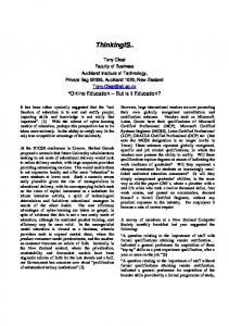
Selections are, in essence, sub processes which are initiated either by operator action or automatically by other active selections. A selection is a sequence of steps that specify the control system's logic. Steps, in turn, are composed of required preconditions, operations, and fault checks. This hierarchical structure is illustrated in Figure 1.
Selections
- Selection 1 Preconditions
- Selection 2
Operates Fault Checks -1
Step n
I Selection n Figure 1. Hierarchical Structure of Selections. Since the selections specify the control logic, the language used to write selections became the focus of the analysis. This language is the topic of the next section. 4.2 Selections A selection is a small, identifiable operation in the manufacturing process. Taken together, the selections that make up an FD constitute a phase in the manufacturing process. An example of a FD is "Tanker Unloading", the manufacturing phase of unloading milk from incoming trucks (tanker plus trailer) into storage silos. This FD consists of 43 selections. Examples are Tanker Bay N Tanker and Trailer water flush, Tanker Bay N Tanker unloading, ~ a n k e r ~N a yTrailer unloading, Tanker Bay N Tanker line flush, andTanker Bay N Trailer lineflush, (in the above, N ranges from 1 - 8) [13]. Each selection is numbered, for example P1001, P1002, etc., sequentially, but this numbering does not imply order of execution. More than one selection may be active at a time. Each selection is made up of one or more sequentially numbered steps, starting with step zero. As with selections, the sequential numbering of steps does not imply a sequential order of execution, and more than one step within a selection may be active concurrently.
Troy and McQueen
7
Individual selections are activated when they are "selected", either by operator action or automatically by a step in another selection. Steps are composed of three sections. All steps have preconditions, and may have operates and checks. Preconditions are a set of predicates that must be true for the step's operates to be activated. These conditions may be events (one-shot conditions) or may be monitored (continuous actions). Operates are actions that are performed as long as all preconditions are true. Checks are conditions that are evaluated after the operates have been applied. If any check is false, this is called a fault and results in a message to the operator. The operates of a step with a fault continue to be applied (as long as the preconditions are all true). A step can thus be in one of four states: not active (if its selection has not been selected), precondition, active, or fault. All steps are independent. More than one step of a selection can be (and usually is) active concurrently. The active steps of a selection are therefore not necessarily sequential. The preconditions of a step define whether that step is active. Preconditions, operates, and checks are coded using structured-English pseudo-code. An example of a step is shown in Figure 2. STEP 10116 (OPEN ROUTE) If all valves on the transfer route that should be closed are checked to be in the correct position, the (water flush shutdown) transfer route is able to be opened Preconditions 1. Step l01/5 Active .And. monitor; selection started monitor; cip interlocks ok 2. No faults Step 101/1 Checks monitor; source silo output closed 3. No faults Step 101/5 Checks Operates transfer line water supply valve 1. Energ (Open) V122 silo S2 gullet valve 2. Energ (Open) V112 silo S2 process inlet valve 3. Energ (Open) V113 Checks transfer line water supply valve 1. V122 Energ (Open) silo S2 gullet valve 2. V112 Energ (Open) silo S2 process inlet valve 3. V113 Energ (Open)
Figure 2. Example of a Step.
5. Prototype CASE Tool Environment 5.1 CASE Tool Architecture To investigate the potential of CASE tools in FD development, a prototype environment was designed and implemented. The goals of the environment are to: Replace generic office automation tools with domain specific CASE tools;
Troy and McQueen
8
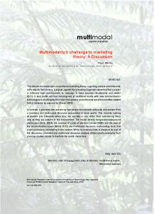
Shift some knowledge from individual people to automated tools by incorporating domain-specific languages and rules to aid user acceptance; Provide flexibility through the use of rule-bases and associated editors (i.e. customizable); Institutionalize FD language standards; Support reusability of FDs using a repository of old FDs; Shift some production steps from manual to automated tools such as generation of analysis reports based on the FD, for example, cross reference reports; Support testing (simulation) of some of the FD logic, thus moving this function up in the life cycle to the specification phase. The architecture of the environment is illustrated in Figure 3, and has similiarities to the work reported in [12]. The primary components of the environment are a CASE tool called the functional description assistant (FDA) and its associated rule bases. Figure 3 illustrates the rule-based architecture of the environment. The function of the rule-bases is to support customization of the language, within a defined structure, and to define application specific information and rules relating to real plant devices that can be enforced by the assistant. Examples are shown in Figure 4.
Troy and McQueen
1 [
Rule Base Editors
1
FD Terminology Rules
I I
Plant Item Type ~ u l e i I
I Plant VO Rules I
I
Specification Assistant
I
I Library of Existing FDs
/
Working or Commissioned FD
Simulation and Analysis Reports
FD changes found in testing (plant simulation or commisssioning) or in maintenance due to new requirements
PLC programmer or automatic code generator
d= I RLL Control Code
PLC Data Table
PLC Vendor's RLL Editor
FD = Functional Description Specification PLC = Programmable Logic Controller RLL = Relay Ladder Logic
Figure 3. CASE Architecture. The CASE tools were implemented as Microsoft Windows applications. Microsoft Visual C++ was utilized in order to take advantage of its support for MS Windows and to implement the software using object-oriented constructs. The following sections describe the rule bases and the FDA in more detail.
Troy and McQueen
5.2 Rule Bases
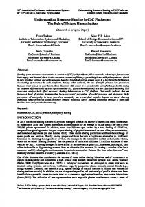
There are three rule bases that support the specification assistant: terminology, plant item type, and plant 110. The function of the rule bases is to allow customization of the assistant, to capture and enforce some rules about plant items and how they can be used, and to capture information to assist code generation. The terminology rule base allows specification of operate and state keywords that are used in writing the FD. The plant item type rule base supports definition of plant item prefixes and associated information about items such as whether an item is digital or analog, the number of inputs and outputs, and the terminology that is permitted to be used with items of each type. The plant VO rule base allows definition of each available plant item, along with a mapping of its 110 points to PLC addresses and terminology in the functional description. Examples of each of these rule bases are shown in Figure 4.
Terminology Rules
>
Functional Description Assistant
Energ, Denerg P Purnp Digital 11 1 0
2
Plant 110 Rules VPlOl Gullet Valve VPlOl Energ 0:110100 VPl OlE Energised 1:060/00 VPlOlD Denergised 1:050/00 P201 Transfer Pump P201 Start 0 : 100100 P201R Running 1:040100
Figure 4. Rule Base Architecture. The terminology rules permit definition of the words to be used for operates, preconditions and checks. In the example above, StartIStop are two operates and the
Troy and McQueen
11
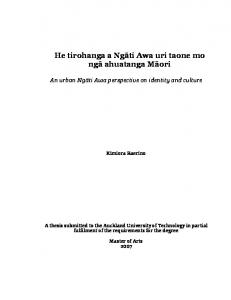
corresponding states are RunningIStopped. This rule-base also allows definition of the valid transitions between operates and states. An example of the user interface for this rule base is illustrated in Figures 5 and 6. Figure
5 shows the top level dialog box for the rule base. Pressing add or selecting an existing term and pressing edit brings up the edit box shown in Figure 6. All rule-bases and the specification assistant have a modification history recording mechanism. This is invoked from any of the tools by pressing the History button, which pops up a history dialog box as shown in Figure 7. The history mechanism serves to document design changes and can be used to audit the evolution of the specification.
Operate
c.sn.!?el
Deenerg Deenerg Energ Flash Energ Initiate Start
State
...........B Deenergised ot.....~ct..~.reeeeeeee .....,.... Off Energised Flashing Active Running Stopped
Figure 5. Top Level Terminology Rule Base Dialog Box.
Figure 6. Terminology rule-base edit dialog.
Figure 7. Modification history dialog box.
Troy and McQueen
12
The Plant Item rules support definition of types of items to be used within the factory and permitted terms from the Terminology rules that may be used with each type. In Figure 4, where the rule bases were introduced, type P (for pump), is a digital device with one input to, and one output from the PLC, and the terms start and stop may be used with an item of type P. As another example, the type VP is a digital device with two inputs, 1 output, and the terms energldeenergise may be used with items of type VP. Types such as P and VP are prefixes for the names, or equipment tags, of the devices on the factory, which are defined in the Plant I10 rule base. The user interface for the Plant Item rule base is similar to the terminology rule base in that it has a top level dialog box for adding, editing, or deleting and edit dialog box that pops up in response to the add or edit buttons. An example of an edit
-I IF0
Flov Totaliser
Analos
1
0
I
1
Figure 8. Plant item rule-base edit dialogs. The Plant VO rule base has an entry for each item in the factory. For example, looking back at Figure 4 above, VPlOl is a CIP (clean in place) supply valve. Its output maps to PLC address 0:110/00 and this output is tagged VPlO1. Its two inputs map to PLC addresses I:50/00 and I:60/00 and are tagged VPlOlD and VPlOlE respectively. The Plant I10 rule base also has a mapping between keywords and PLC addresses. In the example above, VPlOl would map to the operates (EnergIDeenerg), VPlOlD would map to the deenergized state and VPlOlE would map to the energized state. This is illustrated by the edit dialog in Figure 9.
Troy and McQueen
13
Figure 9. Plant I/O rule base edit dialogs.
5.3 Functional Description Specification Assistant The Functional Description Assistant (FDA) is the CASE tool designed to support development and analysis of the control system specification, the Functional Description (FD). It is to be utilized primarily by the process engineer and replaces generic office automation tools (word processor) in the old system. Features of the FDA are that it: Supports the domain-specific specification language; Uses a visual WIMP (Windows, Icons, Menus, Pointer) windows-based interface; Supports a library for storage, retrieval, and modification of designs; Utilizes the rule bases to enforce certain rules, such as correct use of terminology with plant items; Generates some portions of the specification automatically, such as fault checks and item descriptons; Generates analysis reports such as plant itedstep cross references, step summaries, and other reports; Supports some simulation of the FD logic;
Troy and McQueen
14
Contains some support for coordination and control in terms of modification history audits for selections and steps. A primary function of the FDA is to support the creation and reuse of standardized functional descriptions (FDs). The user can choose to create a new FD (using New) or Open an existing FD (using Open). Combining Open with Save As provides one way to reuse existing designs -- the user can open an existing FD, modify it, then save it as a new FD using Save As. Figure 10 shows the initial FDA screen after the existing FD named SAMPLE2 has been o~ened.
Figure 10. Initial Screen After Opening an Existing FD.
Figure 11. FD Menu.
The initial screen (Figure 10) shows the contents of the FD under consideration. Each section of the FD is accessible by pulling down the FD menu (Figure 11) and selecting the desired section. The menu item "Schematic" provides future support for representation of the Process and Instrumentation Diagram (P&ID). The menu items "Selection Summary" and "Execute" are described later in the analysis section. The other menu items are reviewed below. The header (first menu choice in FIgure 11) allows specification of the FD name, its number, a description, and comment field. (The corresponding dialog box is not illustrated.) The Real 110 database (also called the automation database) is a listing of all plant items (and an associated description) that are referenced in the selections. These are a subset of the items defined in the Plant I 0 rule base. Figure 12 shows the Real I 0 dialog.
Troy and McQueen
L1503 Silo S3 Level OP401 Milk Transfer Remote lndicatio P201 Transfer Pump Silo 5 2 CIP Supply Gateswitc Silo 5 3 CIP Supply Gaterwitc Silo S1 CIP Supply Valve Silo S1 Gullet Valve
Figure 12. Real VO Dialog Box. The Real I 0 database can be constructed prior to entering selections, or automatically by the FDA as selections are entered. For example, as the user is entering preconditions, operates, or checks, if a plant item is referenced that is not in the Real VO database, the FDA will automatically enter it. Descriptions are automatically extracted from the Plant I10 database and item type attributes are automatically extracted from the Item Type Database. (These are viewable by using the Attributes button in Figure 12.) The user can also build the Real I 0 database by hand by selecting items from the Plant I 0 rule base and adding them to the Real I 0 database. The selections specify the logic of the control specification. Choosing Selections from the FD menu (Figure 11) will pop up a list of the selections in the FD, as shown in Figure 13. Pressing Add or Edit will pop up the dialog shown in Figure 14.
Figure 13. Selection Dialog Box.
Troy and McQueen
Figure 14. Step Dialog Box. Note the icon just above OK in the lower right of the dialog box. This is a visual cue of the current position in the selection, step, precondition, operate, check hierarchy. The logic of the selection is coded in the steps. The dialog in Figure 14 is used to add, edit, or delete steps. For example, editing Step 2 brings up the step dialog box shown in Figure 15.
PI03 Energ DIP103 Silo S1 Process Outlet Valvel VP122 Energ DIP122 Silo S3 Gullet Valvel VP123 Energ (VP123 Silo 53 Process Outlet Valve)
Steploll5 Not Active
Shutdown step
VP103 Energised DIP103 Silo S1 Process Outlet Valvel VP122 Energised DIP122 Silo S3 Gullet Valvel VP123 Energined (VP123 Silo S3 Process Outlet Valve)
Figure 15. Step Dialog Box. The language derived from the model FD is used to specify the preconditions, operates, and fault checks for each step. Dialog boxes were used to create precondition, operate and
Troy and McQueen
17
fault check "forms" to capture the information. The operates dialog box is illustrated in Figure 16.
Figure 16. Operate Dialog Box. As much information as possible is automatically supplied by the software. This includes automatic numbering of steps, provision of a pick list of available plant items, and, once an item is selected (or entered), its valid operates. Most of this information comes from the rule bases. Other automatic features include the automatic generation of a fault check if the "checked" box is clicked, and automatic insertion into the comment field of the plant item's description from the plant I/O rule base. Notice that operates can be qualified as stored, time delayed, time limited, one shot, or conditional. The Qualifications section of the dialog was derived from ideas in Grafcet [4]. A stored operate is latched on and must be explicitly unlatched in a later operate. Operates can be either time delayed or time limited, thus making use of the PLC's timers. A one-shot operate is enabled for only one scan of the PLC. Finally, operates may be conditional. These qualifications can be combined, and the ordering in which they are combined is important. The ordering is shown in the box above the Stored button in Figure 16. A Delete button (underneath the drop down list) is used to remove qualifications. As an example of the importance of ordering, consider DelayedIConditional versus ConditionalIDelayed. In the former, the condition is applied after the specified delay, whereas in the latter the delay is applied only after the condition is satisfied. Preconditions and checks use similar dialog boxes. All conditions in operates, preconditions, and checks, are highIy structured to remove ambiguity and to support
Troy and McQueen
18
automatic generation of PLC code in the future. A feature of checks is the automatic generation of a fault message, and the collection of these messages in the message portion of the FD. This provides additional support for PLC coding. At the beginning of this sub-section, reference was made to one way that the FDA supports design reuse by using Open and Save As from the File menu. The FDA also supports reuse by supporting the MS Windows multiple document interface, copylpaste, and findlreplace capabilities. The multiple document interface allows the user to open multiple FDs concurrently and copylpaste between them. The copy-paste capability is structured in that it supports the ability to copy selections, steps, or plant items from the real 10 database either within a single FD or between FDs. The findlreplace feature allows the user to replace plant items when reusing an existing specification. Since the FDA has knowledge of the FD, it is also capable of updating the replaced item's entry in the Real 1 . 0Database as well as in any preconditions, operates, or fault checks. These functions are invoked by using the Edit menu items shown in Figures 10 and 13. The FDA supports analysis and inspection of the FD specification in two ways: automatic generation of inspection reports and model-based analysis of the specification. The FDA allows the user to display or print any or all portions of the functional description. Under the File item of the main menu, the user can use the Report Select menu, illustrated in Figure 17 to choose a report to print (or print preview). These reports include each part of the FD, as well as inspection reports that are generated by the FDA.
Figure 17. Report Selection Menu.
Troy and McQueen
19
The FDA automatically generates several reports some of which were produced manually in the old system. Available reports are: Selection Summary. A summary report listing the name, number, and descriptions of every selection in a FD. Step Summary. A summary report listing the name, number, and descriptions of every step in a selection. Item/Step Cross Reference. A report showing each plant item and in which step the item has been referenced. The cross reference is a powerful tool to aid in the inspection of the FD. The designer can use it to determine where (or if) each plant item is utilized. This aids the debugging and modification process. It is also useful as an aid to the plant operator for trouble shooting, once the plant is in operation. An example of the cross reference report is shown in Figure
18.
Figure 18. Item/Step Cross Reference. The CASE tools increase productivity by replacing manual production of reports with automation. Also, because of the ease with which they can be generated, the designer can produce intermediate versions of these reports as helshe is developing a specification. In the old system the designer would not generate intermediate versions of these reports because of the time required to do so. To assist the designer in analyzing alternatives and debugging the specification, the FDA supports model-based analysis, which is simulation (execution) of the specification. The goal
Troy and McQueen
20
of this feature is to permit the designer to test the relationship of steps and their constituent preconditions, operates, and states. Researchers argue that development environments should provide a means for modelling the system and techniques for inspecting and analysing the model [6]. This is consistent with the finding that one of the major dimensions of CASE technology is the support of design analysis [7]. Further support comes from Kopetz who identifies support for evaluation of the design before initiating the test phase as one of the requirements for a process control development system [9]. Using the FDA, the engineer can monitor the state of selections, steps, and plant items, by manually changing certain states and then letting the FDA simulate the execution of preconditions, operates and checks. The dialogs below illustrate the ideas. First, the user can monitor the state of selections or "force" them into new states. This is shown in the Figure 19 where the sel
Figure 19. Selection States. Selecting a selection and pressing the "Selection" button allows the user to monitor the state of steps and also to force states and individual plant items into new states. See Figures 20 and 21.
1
2 3 4 5 6
Route Check Open Route Start Transfer Running Shutdown
Cancel
Troy and McQueen
Figure 20. Examining Step States.
Figure 21. Forcing the State of Steps or Items. After forcing the state of steps and individual plant items in order to model an operational scenario, pressing the "Execute" button will cause the FDA to simulate the step logic and update the states of the selections, steps, and plant items to reflect the logic in the preconditions, operates and checks of the given selection. After execution, Figures 19 and 20 would be updated to reflect any state changes in selections and steps, respectively, and the updated item states can be examined by pressing the Items button in Figure 20, giving the dialog shown in Figure 22.
Flashing Not Running Deenergised Deenergised Deenergised
Figure 22. Updated State of Steps after Execution. By using model-based analysis the engineer can test some of the FD's logic prior to code generation and potentially detect errors earlier in the software development life cycle. This also permits analysis of alternatives in the FD logic prior to code generation. For example, suppose that closing a valve should result in a fault and that as a result several steps should move from the active to the fault state. To test this, the designer could force the appropriate valve into the closed state, press execute, and verify the new state of the steps. Although this form of simulation is not sufficient to discover all errors, it can aid in discovering problems in the control system's logic.
Troy and McQueen
6. Conclusions This work produced a prototype CASE tool environment to support the specification and coding of PLC control software. Significant aspects of the tools are the incorporation of domain methods, model-based analysis (simulation), and flexibility through the use of rule bases. The prototype has been introduced to practitioners at Anchor and also to contractors associated with Anchor. Initial experiences indicate that the domain specific CASE tools will be effective in supporting the software development life cycle for the production of control software for programmable logic controllers. The domain-specific specification language is a significant factor in potential adoption of the CASE tools by practitioners. The standardization of the specification, imposed by the use of the CASE tools, and model-based analysis show considerable potential to improve productivity and quality. The potential of automatic code generation is under investigation. A significant difficulty in automatic code generation in this domain is that in the testing and maintenance phases, a code generator must support on-line modification of PLC code. On-line modification of the PLC code is necessary because, once in production, the PLC cannot be taken off line to reload the code. In the dairy processing domain, the PLC runs continuously for months without shutdown. To implement an automatic code generator that supports on-line programming, considerable information and support is required from the PLC manufacturer because on-line communication with the PLC utilizes proprietary protocols. Our investigation is proceeding on two fronts. First, we are studying the potential impact of the CASE tools on the quality of FD specifications and resulting PLC software, the productivity of those involved in the process, the effect of standardizing the structure and content of software specifications, and organizational communication and roles. The second thrust is to determine the key requirements of a CASE environment in the domain of dairy process manufacturing, those requirements that can be implemented, and the strengths and shortcomings of the tools. We are currently investigating the effectiveness of the overall CASE tool architecture, the domain specific methods, model-based analysis, and the potential to automatically generate code for PLCs from the specification.
References 1.
2.
3.
Basili, V.R.B. and Rombach, H.D. The TAME Project: Towards Improvement-Oriented Software Environments. IEEE Transactions on Software Engineering 14,6 (June 1988), 758-772. Chaar, J.K., Voltz, R.A., and Davidson, E.S., An Integrated Approach to Developing Manufacturing Control Software. In Proceedings of the 1991 IEEE International Conference on Robotics and Automation, IEEE, Sacramento, California, April 1991, pp. 1979-1984. Dart, S.A. Software Development Environments. IEEE Computer 20, 11 (November 1987), 18-28.
Troy and McQueen
23
David, R. and Alla, H. Petri Nets & Grafcet Tools for modeling discrete event systems, Prentice Hall International, Hertfordshire, UK (1992). Fuggetta, A., di Milano, P., and CEFRIEL. A Classification of CASE Technology. IEEE Computer 26, 12 (December 1993), 25-38. Harel, D. Biting the Silver Bullet Toward a Brighter Future for System Development. IEEE Computer 2 5 , 1 (January 1992), 8-20. Henderson, J.C. and Cooprider, J.G. Dimensions of 11s Planning and Design Aids: A Functional Model of CASE Technology. Information Systems Research 1 , 3 (September 1990), 227-254. Higginson, J. PLC Software Moves into the New Decade. Control & Instrumentation 2 2 , 4 (April 1990), 90-91. Kopetz, H. The design of real-time systems: from specification to implementation and verification. Software Engineering Journal (May 199I), 72-83. Neidert, R. The Object Oriented Paradigm and Industrial Control. In IPC '91 Proceedings of the 20th Annual ESD International Programmable Controllers Corzference and Exposition, ESD-The Engineering Society, ESD, Detroit, Michigan, April 1991, pp. 495-505. Potts, C. Software-Engineering Research Revisited. IEEE Software (September 1993), 19-28. Roberts, C.A. Generation of Relay Ladder Logic From A Real-Time Network Control Specification, Ph.D. dissertation, Virginia Polytechnic Institute & State Univ., May 1990. Wise, M., Tanker Unloading Functional Description, Ashton Project Services Ltd., Hamilton, New Zealand, Third Revision, February, 1994.