1
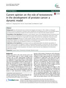
A chemical model for dynamic workflow coordination Manuel Caeiro∗ , Zsolt N´emeth† and Thierry Priol‡ ∗ E.T.S.E. Telecomunicaci´ on University of Vigo, Campus Universitario, E-36310 Vigo Email:
[email protected] † MTA SZTAKI Computer and Automation Research Institute P.O. Box 63., H-1518 Hungary Email:
[email protected] ‡ IRISA, Campus Universitaire de Beaulieu 35042 Rennes, Cedex, France Email:
[email protected]
Abstract—This paper investigates a chemical workflow enactment model that is intended to coordinate workflows of large set of activities on a large number of resources in a self-evolving nature, based on a chemical analogy. The concept of chemical workflow engine is introduced for a concurrent, self-coordinating enactment exploiting as much parallelism as inherently present. The concept is aimed at supporting a generalized workflow language without any restrictions, modeling most workflow patterns, separating data and control flow, supporting dynamic changes by multiple versions and instances. The paper presents the notion and model of the chemical based coordination. Index Terms—nature inspired computing, formal model, dynamic workflow
I. I NTRODUCTION The notion of workflows was borrowed from the business world and has emerged as a paradigm for executing complex distributed computations; in recent years became a dominating model for many scientific applications. Therefore, their various aspects have been well studied and some of their characteristic and partly unsolved challenges are summarized as: they are dynamic where decisions are made based on the latest available information; a workflow may be dynamically altered according to the results at a certain point in progress; the basic structure or the semantics of the workflow may change to some external events; workflows may breakdown and fail; workflows may have an evolution by refinements. Both the workflow and the infrastructure are in continuous change [1]. We focus our work on the enactment of scientific (i.e. computation intensive) workflows albeit the same problems appear in different settings like service compositions, for instance. In fact, workflow is just a proper example to study the potential of a non-conventional, chemical modeling approach. The research presented in this paper is driven by the observation that enactment of scientific workflows in an everchanging (with respect to performance and availability) and fault prone distributed heterogeneous computing environment requires a complex coordination. Potentially, available information may be partial or not up to date. Furthermore, the
presence of advanced workflow patterns [2] also may introduce some degree of uncertainty. We assume that such coordination requires frequent and abrupt changes where no predefined or static approaches are feasible. Coordinating a large-scale system is far beyond the capabilities of humans even more, the complexity of such control is increasing so that even machines cannot cope with all possible or potential cases based on predefined conditions and algorithms. With the advent of the notion of autonomic computing [3] it became evident that such systems must exhibit some degree of autonomy, able to adapt to changes and they should provide some self-* properties. Most algorithms nowadays are sequential, expressed in imperative programming languages making the description of such algorithms complex and potentially incomplete. Nature-inspired formalisms may offer a well defined mechanism to find a more adequate solution. The current stage of our work is not aimed at establishing autonomous behavior based on a nature inspired computational model rather, to establish a nature inspired formal framework where such models can be realized. Nature models have been applied to various problems, especially scheduling and optimization in the context of scientific workflows. Particle swarm based workflow scheduling and optimization is proposed by Abraham et al. [4] and Pandey et al. [5]. Sun et al. [6] take a neuroendocrine-immune system as a model and create a decentralized, evolutionary, scalable, and adaptive system for E-services workflow. Prodan et al. [7] apply genetic algorithm for static scheduling of DAG type workflows. Genetic algorithms appear in a particular aspect of workflow scheduling by Spooner et al. [8]. Simulated annealing was considered by Young et al. [9] for scheduling grid workflows. In contrast, instead of solving some particular problems of workflows, our approach focuses on modeling and tries to put the entire workflow enactment into an abstract chemical framework, with a special emphasis on its dynamic behavior. Artificial chemistries are man-made systems that are similar to a real chemical system [10]. Dittrich et al. classify three main
2
axes of applying artificial chemistry: modeling, information processing and optimization. In this paper we explore the modeling aspect and the work is similar to [11], [12] where Banˆatre et al. use a chemical model to express various issues related to self-organizing services and service invocations and also related to [13] where earlier studies with modeling static workflows using 𝛾-calculus were done. Workflows may change during execution due to any condition unforeseen at planning, user intervention, changes in the environment or for adaptation reasons. Changes may involve structural, functional, parametric changes; there may appear several versions and instances of the same workflow definition. The aim is to create a model that is flexible and allow establishing a fully dynamic enactment of workflow that can lead later to various adaptation strategies. We imagine a system that is able to react to any changes in its own behavior or the embedding conditions. A metaphor we took is chemistry: just like chemical reactions are self-governing, self-balancing, self-evolving processes, an ”idealistic” distributed workflow enactment should possess many of these features. The contribution of this paper is a methodology by developing an abstract model for the Chemical Workflow Engine (CWE). The work is based on thorough requirement analysis and is in partial alignment with the major challenges of scientific workflow [1]. The main considerations are: (i) support for a generalized workflow language without any restrictions; (ii) a clear separation and detailed model of data and control flow; (iii) modeling events and connectors to generalize control in the chemical model; (iv) support for dynamic structural and semantic changes by multiple workflows / multiple versions / multiple instances; (iv) detailed analysis of some fundamental constructs modeled as chemical entities and reactions.
of computer science (sorting, prime testing, string processing, graph algorithms, etc.) can be expressed in Gamma in a more natural way than applying any other sequential semantics. Based on the notion of the Gamma formalism, a higherorder model called 𝛾-calculus [15] was conceived. In this calculus every element is considered as a molecule. Programs are made of Active Molecules (AMs), embedding reaction rules and actions, and Passive Molecules (PMs) representing data. AMs can capture AMs and/or PMs and produce new AMs and/or PMs in accordance with their reaction rules and actions. Also, AMs do vanish in reactions. In contrast, Gamma represented data entities as molecules and reaction rules were outside of the solution (no notion of molecules), they remained intact after a reaction. The Higher Order Chemical Language (HOCL) [16] is a language based on the 𝛾-calculus extended with expressions, types, pairs, empty solutions and names. HOCL uses the selfexplanatory replace... by... if... construct to express active molecules. replace 𝑃 by 𝑀 if 𝐶 formally corresponds to 𝛾(𝑃 )⌊𝐶⌋.𝑀 with a major difference: while 𝛾-abstractions are destroyed by the reactions, HOCL rules remain in the solution. replace... by... if... is followed by in ⟨...⟩ that specifies the solution the active molecule floats in. Notable extensions of HOCL are: types that can be added to patterns for matching; pairs in form of 𝐴1 : 𝐴2 where 𝐴1 and 𝐴2 are atoms; and naming that allows to identify and match active molecules. For example, let 𝑖𝑛𝑐 = replace 𝑥 by 𝑥 + 1 in ⟨1, 2, 3, 𝑖𝑛𝑐⟩
II. T HE ORIGINS OF THE CHEMICAL MODELING This work applies a certain chemical modeling approach hence, its background, the family of the Gamma language (Gamma, the 𝛾-calculus and the Higher Order Chemical language) are summarized here briefly. Note, this way of chemical modeling is different from computational (artificial) chemistries: while they model and simulate real chemical processes, our chemical model takes chemistry as a modeling metaphor. The first notion of the chemical model has been introduced as the Gamma formalism [14] to capture the intuition of computation as the global evolution of a collection of interacting elements (e.g., molecules). Gamma can be introduced intuitively through the chemical reaction metaphor. Programs are conceived as chemical solutions involving a (multi)set of molecules that can react in accordance with certain reaction conditions and actions. Computation proceeds by capturing the molecules satisfying certain reaction conditions and replacing them by the molecules specified in the actions; there is no concept of any centralized control, ordering, serialization rather, the computation is carried out in an indeterministic way according to local conditions. The result of a Gamma computation is obtained when a stable state is reached, namely, when no more reactions can take place. It has been shown in [14] that some fundamental problems
specifies an active molecule named 𝑖𝑛𝑐 which captures an integer and replaces it with its successor, floating in a solution together with integers 1,2,3. III. T HE GENERALIZED NOTION OF WORKFLOW REPRESENTATION
Due to the lack of standardized workflow languages we assume a general representation, not committed to any existing workflow language in order to demonstrate the capabilities of our model. ∙ Function represents an activity of the workflow, a task to be realized, such as the execution of a certain program. Functions usually require some input Data Elements that have to be processed in order to produce some output Data Elements. In addition, Functions need to be assigned to appropriate Resources ∙ Connectors support the description of control- and dataflow dependencies. There are different types of Connectors related to the control flow, such as splits and joins, or related to the data flow, such as the break down of a large data set into several smaller chunks of data. Connectors may involve the management and processing of Data Elements, as input and output items.
3
Events represent a state before and/or after a Function or Connector is traversed. This element is strongly related to the control flow issues of workflows. ∙ Data Element represents a container of data used during the workflow execution. Data Elements are taken as input by Functions and Connectors. ∙ Resource is an entity necessary to realize the activity represented by Functions. Each resource includes a description of its capabilities and features, enabling the matching of appropriate Resources to Functions. Control-flow is expressed by explicit connections between Functions and Connectors through Events. Any Function must be preceded by just one Event and succeeded by another Event. Similarly, a Connector must be preceded by one or several Events and succeeded by one or several Events, depending on the Connector type. Further constraints are: (i) it is not possible to connect two Events one to another and (ii) there is at least one start Event and at least one final Event representing the start and finish of the workflow, respectively. Data-flow is expressed implicitly by identifiers assigned to data elements and input and output parameters in Functions and Connectors. The expressiveness and generality of the experimental notation comes from the connector types ranging from typical control-flow connectors to more specific ones used in scientific workflows: data loops [17] or the one-to-one and all-toall connectors from SCULF [18]. Control-flow connectors are typically divided into four categories: sequential, parallel, conditional and iterative constructs. We considered the parallel and conditional connectors similarly to workflow languages such as Event-driven Process Chains (EPCs) [19] and YAWL [20]: AND-split/AND-join, OR-split/OR-join, and XOR-split/XOR-join connectors. In addition, our generalized concept also includes loops and sub-process calls. ∙
IV. T HE ABSTRACT MODEL OF THE C HEMICAL W ORKFLOW E NGINE A. Molecules of the Chemical Workflow Engine The coordination of workflow enactment is envisioned as an analogy of chemical reactions where Active Molecules (AMs) and Passive Molecules (PMs) are dissolved forming a chemical solution (or solutions) and they engage in reactions. Reactions are realizing the ’computational step’; by a series of reactions the chemical matter evolves so that every reaction is driven by actual and local conditions. The execution goes on as long as there are molecules to react. If there are no more reactive molecules, i.e. the solution is inert, the execution stops. It is possible that some external events (e.g. user intervention) insert molecules that perturb the inertia. Exactly this manner makes it possible to realize dynamic adaptation, the execution can be controlled. The whole computation is not a sequence of instructions rather, a dynamically changing set of molecules that evolves according to some rules in an inherently concurrent and autonomic way. The notion of the Chemical Workflow Engine (CWE) tries to realize this metaphor. The coordination is based on the interaction of specific AMs and PMs that are representing the elements of the workflow. Particularly, Func-
tions (set 𝐹 𝑈 𝑁 𝐶𝑇 𝐼𝑂𝑁 = {𝑓1 , 𝑓2 , ...𝑓𝑘 }) and Connectors (𝐶𝑂𝑁 𝑁 𝐸𝐶𝑇 𝑂𝑅 = {𝑐1 , 𝑐2 , ...𝑐𝑙 }) are AMs (because they involve some kind of processing or control, while Events (𝐸𝑉 𝐸𝑁 𝑇 = {𝑒1 , 𝑒2 , ...𝑒𝑚 }), Data Elements (𝐷𝐴𝑇 𝐴 = {𝑑1 , 𝑑2 , ...𝑑𝑛 }) and Resources (𝑅𝐸𝑆𝑂𝑈 𝑅𝐶𝐸 = {𝑟1 , 𝑟2 , ...𝑟𝑝 }) are represented as PMs. All these molecules are put into a solution called 𝑚𝑎𝑖𝑛 that represents the coordination space: 𝑚𝑎𝑖𝑛 = ⟨𝐹 𝑈 𝑁 𝐶𝑇 𝐼𝑂𝑁, 𝐶𝑂𝑁 𝑁 𝐸𝐶𝑇 𝑂𝑅, 𝐸𝑉 𝐸𝑁 𝑇, 𝐷𝐴𝑇 𝐴, 𝑅𝐸𝑆𝑂𝑈 𝑅𝐶𝐸⟩ It is important to indicate that molecules are abstract entities: Data Elements and Resources contain references to the real data elements and resources, but they are not the actual items. Similarly, Functions do not contain the programs (actual code) that they require to execute, but references to such entities. We represent all PMs (Events, Data Elements and Resources) as sub-solutions separated from the coordinating 𝑚𝑎𝑖𝑛 solution by a membrane. Attributes form pairs within the sub-solution. The generic form is: ⟨𝑎1 : 𝑣1 , 𝑎2 : 𝑣2 , ... 𝑎𝑛 : 𝑣𝑛 ⟩ where each 𝑎𝑖 : 𝑣𝑖 is an attribute-value pair yielding a profile for a certain entity. The exact number of attributes and their meaning is entity-dependent; we do not specify any strict format at this level of abstraction. Such a sub-solution may contain any molecules (attributes) in any order as long as the notation is consistent. Thus, an event, for instance, may be represented as 𝑒5 = ⟨𝑒𝑣𝑒𝑛𝑡, 𝑛𝑎𝑚𝑒 : 𝐴, 𝑖𝑑 : 12, 𝑎𝑝𝑝𝑙𝑒, 23, ...⟩ an event tag, an event name ’A’, an ID and some other unspecified parameters. Since molecules engage in reactions by pattern matching, the presence or absence of certain patterns (values) is crucial, like the tag, name and ID but other molecules are indifferent and may be omitted, like apple and 23 in this example. As we will see, identifiers have a very important role in this model. Data Elements can be represented in a very similar way, e.g. 𝑑12 = ⟨𝑑𝑎𝑡𝑎, 𝑛𝑎𝑚𝑒 : 𝑋, 𝑖𝑑 : 42, 𝑣𝑎𝑙𝑢𝑒 : 𝑛𝑖𝑙, ...⟩ the nested solution may contain data items, references to data and metadata to describe the content. One may imagine them as (self-describing) data structures in conventional languages. Analogously, Resources are represented in a quite self-explanatory way 𝑟1 = ⟨𝑟𝑠𝑐, 𝑡𝑦𝑝𝑒 : 𝑐𝑜𝑚𝑝, 𝑝𝑟𝑜𝑐 : 16, 𝑂𝑆 : 𝐿𝑖𝑛𝑢𝑥, ...⟩ in 𝑚𝑎𝑖𝑛 = ⟨𝑟1 , 𝑒5 , 𝑑12 ...⟩ putting all the above PMs into the coordinating solution. The reaction rules and actions of the AMs in the CWE specify matching the appropriate PMs and generating new PMs and AMs. Particularly, Functions have to match the appropriate input Data Elements, the input Event and the required Resources. When the right molecules are matched, they are all removed from the chemical solution, and as an external call,
4
the program (or other activity) corresponding to the Function is executed using the matched input Data Elements and the matched Resource. When the execution is finished, the output Data Elements and the output Event are generated as results and put as molecules in the chemical solution. Similarly, molecules representing the utilized Resources appear again in the solution, since these resources are available again. Thus, the generic form of a function molecule is a simple rewriting rule:
(2) Assignment of Data Elements to Functions and Connectors. Once EAM instances are created, Function and/or Connector EAMs are matched with Data Element PMs. This reaction is different for Functions and Connectors. In the case of Function a new molecule, named as Ready Active Molecule (RAM), is created that represents together the Function and the matched Data Elements. The corresponding refinement, i.e. the definition of 𝑒.𝑓𝑖 in Eq. 3 is
𝑓𝑖 = replace 𝑑𝑖𝑥 , 𝑒𝑖𝑦 , 𝑟𝑖𝑧 by 𝑑𝑖𝑥′ , 𝑒𝑖𝑦′ , 𝑟𝑖𝑧
where 𝑑𝑖𝑥 ∈ 𝐷𝐴𝑇 𝐴 and 𝑟.𝑓𝑖 ∈ 𝐸.𝐹 𝑈 𝑁 𝐶𝑇 𝐼𝑂𝑁 × 𝐷𝐴𝑇 𝐴, i.e a parametrized instance. In case of Connector EAMs, the output Event and the output Data Element PMs are created. In both cases Data Element 𝑑𝑖𝑥 acts as a catalyst: it ignites the reaction but remains intact for further activations. (3) Assignment of Resources to Functions. After Function RAMs are created, they are matched with Resource PMs yielding an Initiated Active Molecule (IAM), representing the execution of the Function with the resources using data elements. Formally,
(1)
where 𝑓𝑖 ∈ 𝐹 𝑈 𝑁 𝐶𝑇 𝐼𝑂𝑁 , 𝑑𝑖𝑥 , 𝑑𝑖𝑥′ ∈ 𝐷𝐴𝑇 𝐴, 𝑒𝑖𝑦 , 𝑒𝑖𝑦′ ∈ 𝐸𝑉 𝐸𝑁 𝑇 and 𝑟𝑖𝑧 ∈ 𝑅𝐸𝑆𝑂𝑈 𝑅𝐶𝐸. This is a simplified presentation: real function molecules may capture and yield multiple data, event and resource molecules. The behavior of Connector AMs is similar to the Functions but they do not require any Resources. Connectors have to match the appropriate input Data Elements, the input Event or set of Events. When the right molecules are matched, the reaction is ignited: the molecules are eliminated from the solution and the corresponding Connector is processed. As a result, Data Elements and the output Event(s) are introduced again in the chemical solution. Formally, 𝑐𝑖 = replace 𝑑𝑖𝑥 , 𝑒𝑖𝑦 by 𝑑𝑖𝑥′ , 𝑒𝑖𝑦′
(2)
where 𝑐𝑖 ∈ 𝐶𝑂𝑁 𝑁 𝐸𝐶𝑇 𝑂𝑅, 𝑑𝑖𝑥 , 𝑑𝑖𝑥′ ∈ 𝐷𝐴𝑇 𝐴 and 𝑒𝑖𝑦 , 𝑒𝑖𝑦′ ∈ 𝐸𝑉 𝐸𝑁 𝑇 . This general description is a ground model, adding more details thus, refining a model may reveal four states of the molecules that would be modeled as four reaction phases (cf. Figure 1): (1) Instantiation of Function and Connector AMs means matching the Function and/or Connector AMs with Event PMs. This reaction yields a new molecule, named as Enabled Active Molecule (EAM) representing the corresponding Function or Connector. The Function and Connector AMs (should be really named as Disabled Active Molecules DAMs) behave like a catalyst in this reaction: they remain intact. Therefore, the DAMs can react again with new Event PMs to generate new EAMs thus, allowing the creation of several instances of the same Function or Connector. Formally, 𝐹 𝑈 𝑁 𝐶𝑇 𝐼𝑂𝑁 and 𝐶𝑂𝑁 𝑁 𝐸𝐶𝑇 𝑂𝑅 sets are refined as 𝐹 𝑈 𝑁 𝐶𝑇 𝐼𝑂𝑁 = 𝐷.𝐹 𝑈 𝑁 𝐶𝑇 𝐼𝑂𝑁 + 𝐸.𝐹 𝑈 𝑁 𝐶𝑇 𝐼𝑂𝑁 so that 𝐷.𝐹 𝑈 𝑁 𝐶𝑇 𝐼𝑂𝑁 ∩ 𝐸.𝐹 𝑈 𝑁 𝐶𝑇 𝐼𝑂𝑁 = ∅ and 𝐶𝑂𝑁 𝑁 𝐸𝐶𝑇 𝑂𝑅 = 𝐷.𝐶𝑂𝑁 𝑁 𝐸𝐶𝑇 𝑂𝑅 + 𝐸.𝐶𝑂𝑁 𝑁 𝐸𝐶𝑇 𝑂𝑅 so that 𝐷.𝐶𝑂𝑁 𝑁 𝐸𝐶𝑇 𝑂𝑅 ∩ 𝐸.𝐶𝑂𝑁 𝑁 𝐸𝐶𝑇 𝑂𝑅 = ∅ differentiating the disabled and enabled molecules. The ”disabled” molecule is the template or the definition of the function/connector whereas the ”enabled” one is a cloned instance of it. The cloning is triggered by event 𝑒𝑖𝑦 . Thus, the corresponding refinement of the function molecules (Eq. 1) is: 𝑑𝑖𝑠𝑎𝑏𝑙𝑒𝑑.𝑓𝑖 = replace 𝑒𝑖𝑦 by 𝑒𝑛𝑎𝑏𝑙𝑒𝑑.𝑓𝑖
(3)
where 𝑑𝑖𝑠𝑎𝑏𝑙𝑒𝑑.𝑓𝑖 ∈ 𝐷.𝐹 𝑈 𝑁 𝐶𝑇 𝐼𝑂𝑁 and 𝑒𝑛𝑎𝑏𝑙𝑒𝑑.𝑓𝑖 ∈ 𝐸.𝐹 𝑈 𝑁 𝐶𝑇 𝐼𝑂𝑁 The refinement of Eq. 2 is similar.
𝑒𝑛𝑎𝑏𝑙𝑒𝑑.𝑓𝑖 = replace 𝑑𝑖𝑥 by 𝑟𝑒𝑎𝑑𝑦.𝑓𝑖 , 𝑑𝑖𝑥
𝑟𝑒𝑎𝑑𝑦.𝑓𝑖 = replace 𝑟𝑖𝑧 by 𝑖𝑛𝑠𝑡.𝑓𝑖
(4)
(5)
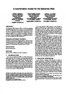
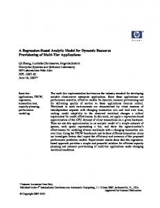
∈ 𝑅𝐸𝑆𝑂𝑈 𝑅𝐶𝐸 and 𝑖𝑛𝑠𝑡.𝑓𝑖 ∈ where 𝑟𝑖𝑧 𝐸.𝐹 𝑈 𝑁 𝐶𝑇 𝐼𝑂𝑁 × 𝑅𝐸𝑆𝑂𝑈 𝑅𝐶𝐸, i.e an instance with an assigned resource. (4) Termination of execution of Function. IAMs are reacted and output Event, output Data Element and Resource PMs are created. Note that this reaction is external to the coordination model. We provide its chemical specification (semantic equivalence) but it is not realized by the engine itself. 𝑒𝑥𝑡𝑒𝑟𝑛𝑎𝑙 𝑒𝑥𝑒𝑐𝑢𝑡𝑖𝑜𝑛 = replace 𝑖𝑛𝑠𝑡.𝑓𝑖 by 𝑑𝑖𝑥′ , 𝑒𝑖𝑦′ , 𝑟𝑖𝑧 (6) As it can be seen, Eqs. 3, 4, 5 and 6 are a refinement of Eq. 1 and they can be derived similarly for connectors. B. Solutions of the Chemical Workflow Engine The four execution states of the workflow activities conceived as four reaction phases are reacted in chemical subsolutions arranged accordingly, as represented in Figure 1. In the chemical model, reactions occur according to laws of locality (also called as chemical law): if a reaction can occur, it will occur in the same way irrespectively to the environment; and of solution (also called as membrane law): reactions can occur in nested solutions or in other words, solutions may contain sub-solutions separated by membranes. A chemical sub-solution is a contained space of chemical molecules that can react without any interference from the outside world until no more reactions can be produced inside the sub-solution, i.e. it becomes inert [15]. The four states and corresponding sub-solutions are the followings: ∙ Disabled. This sub-solution contains Functions and Connectors as Disabled Active Molecules (DAMs) that cannot be processed yet because they have not been activated.
5 Disabled Sub-solution
Enabled Sub-solution DATA INTRODUCTION
ASSEMBLING
Data Elements
Enabled Connectors
Enabled Connectors
Disabled Connectors INSTANCE CREATION
Enabled Functions
(1)
Enabled Functions
Disabled Functions
(2) Events
Events
Ready Functions (3)
(2) (5) Events (6)
Initiated Functions
Ready Functions
Data Elements
Initiated Functions (4)
Resources
Initiated Sub-solution
Fig. 1.
∙
∙
∙
belong to, respectively. Events include both the Process Schema Identifier, the Instance Identifier and Thread Identifier. They are the connection between the elements of the process description and the instance-thread data elements. EAMs, RAMs and IAMs take the three identifiers as they are generated from Events. These three identifiers are used to constrain the matching among molecules. Two molecules can be matched if they share the Process Schema Identifier, the Instance Identifier and the Thread Identifier. In this way, as molecules with different identifiers can not be matched, it is supported the operation of several instances of several processes by the same CWE. ∙
Resources
RESOURCE INTRODUCTION
Ready Sub-solution
The chemical workflow engine
Enabled. This sub-solution contains Functions and Connectors that can not be processed because they have not captured the required input Data Element(s). Ready. This sub-solution contains Functions ready to be executed, but that have not been assigned to any Resource. Initiated. This sub-solution contains Functions that are being executed by assigned Resources, carrying out the intended work (e.g., the execution of a program).
C. Identifiers The CWE is designed to support the operation of several workflows simultaneously, each one involving potentially multiple instances. It supports a scenario taken from [1]: a workflow may be dynamically (re)designed according to the results and progress of initial steps; decisions can be made at run-time how to carry on with the computation. The support of several processes with several instances is managed in the CWE through the use of distinguished identifiers: a Process Schema Identifier (PSI) and an Instance Identifier (II). The Process Schema Identifier distinguishes the several process descriptions. This identifier is composed by two parts: process number and version number. The version number is initially fixed to zero. Each time a modified node is introduced, the version identifier may require to be changed for such node. Meanwhile, the Instance Identifier distinguishes the several executions or instances. Related to the Instance Identifier, an additional, Thread Identifier (TI) may be maintained in some special cases. This is required if a workflow instance can include several threads in parallel, involving the same elements. Therefore, it is required to distinguish between the different threads. These identifiers are related to the molecules in the following way: ∙ Function and Connector DAMs include the Process Schema Identifier that represents the process description they belong to. ∙ Data Elements include the Instance Identifier and Thread Identifier that represents the instance and thread they
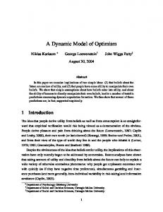
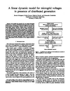
V. R EACTIONS OF THE CWE This section presents a detailed description of Functions and (due to space limitations) some of the Connectors, in the different states. A. Functions Workflow activities represented by Functions are activated by successively traversing the four states: disabled, enabled, ready and initiated. In terms of the chemical metaphor, AMs are reacted in four successive phases, in four separate subsolutions. Figure 2 shows the representation of a Function (top of the figure), preceded and succeeded by an Event, and its chemical processing ((i)-(iv) in the figure). Prior to enactment, activities corresponding to Function are mapped to Function DAMs thus, entering symbolically the chemical world and forming the first solution. The chemical processing of Functions involves the following reactions: i the reaction of the Function DAM with an appropriate Event molecule yields the Function EAM. The condition of the reaction is the appropriate matching of the identifiers of the Function DAM and the Event. In the action the Event molecule vanishes, a Function EAM appears while the Function DAM is a catalyst; ii the next reaction of the Function EAM with the appropriate Data Element molecules produces the Function RAM. Similarly, the condition of the reaction is the appropriate matching of the identifiers of the Function EAM and the Data Element. In the action the Function EAM molecule vanishes, a Function RAM appears while the Data Element molecules remain is a catalyst; iii the reaction of the Function RAM with an appropriate Resource molecule produces a new Function IAM while both matched molecules disappear; and iv the reaction of the Function IAM generates a new Event, Data Element and Resource molecules. This last reaction is external: the chemical model coordinates but does not execute the actual Function. In this way, the workflow engine takes the Function IAMs and assigns the corresponding task (actual code to be executed) to physical resource(s) and stages the necessary matched data elements. The resulted new molecules: Event represents the state after the execution of the activity, Data Element is the result of the execution and Resource stands for the released resource(s).
6
Event A
Function DAM Event A
Function
Event B
Function DAM
Function EAM
Function EAM
Data Elements
(i)
Function RAM (ii)
Data Elements
Event B Function RAM (iii)
Function IAM
Function IAM
(iv)
Data Elements
Resource Resource
Fig. 2.
The execution behavior of Functions
iv The new Decrement (1) EAM reacts with the Event Counter Data Element and results the Event Counter Data Element with a decreased value by 1. In addition, when the value of the counter is zero it generates an Event D molecule. In this way, the synchronization is realized when the number of threads captured is equal to the number of threads initiated in the AND-split Connector. Here we have two molecules: 𝑒.𝑑𝑒𝑐 =replace ⟨𝑑𝑎𝑡𝑎, 𝑒 𝑐𝑜𝑢𝑛𝑡, 𝑣𝑎𝑙𝑢𝑒 : 𝑥, 𝑖𝑑 : 𝑞...⟩ by ⟨𝑑𝑎𝑡𝑎, 𝑒 𝑐𝑜𝑢𝑛𝑡, 𝑣𝑎𝑙𝑢𝑒 : 𝑥 − 1, 𝑖𝑑 : 𝑞...⟩ if 𝑥 > 0 and 𝑒.𝑑𝑒𝑐 =replace ⟨𝑑𝑎𝑡𝑎, 𝑒 𝑐𝑜𝑢𝑛𝑡, 𝑣𝑎𝑙𝑢𝑒 : 0, 𝑖𝑑 : 𝑞...⟩ by ⟨𝑒𝑣𝑒𝑛𝑡, 𝑛𝑎𝑚𝑒 : 𝐷, 𝑖𝑑 : 𝑞...⟩
B. AND-Split and AND-join Connectors
...
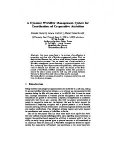
Figure 3 shows the representation and execution behavior of Event B.1 the AND-split and AND-join Connectors. Prior to enactment, AND-split and AND-join Connectors of the workflow are Event A AND-split translated into AND-split and AND-join DAMs of the chemical Event B.N world, respectively. Event B.1 The behavior of these two Connector DAMs is developed as follows. (For the sake of simplicity we present the HOCL AND-split AND-split AND-split Event B.N terms in an drafty way with not all details. Also, we do DAM DAM EAM (i) not specify all identifiers (PSI, II, TI), just a symbolic 𝑖𝑑 (ii) Event Event A ANY-Data AND-split Counter representing that the identifiers must match – unless the precise Element EAM identifier has an importance.) ANY-Data Element i The AND-split DAM reacts with Event A and produces Event C.1 a corresponding AND-split EAM. The condition of the reaction is the matching of appropriate identifiers of AND-join Event D AND-split DAM and Event A. Event A vanishes (the Event C.N very same event cannot trigger any further splits of the same instance) whereas the AND-split remains intact as Event D AND-join Decrement (1) a catalyst. AND-join DAM EAM DAM Event 𝑑𝑖𝑠𝑎𝑏𝑙𝑒𝑑.𝑎 𝑠𝑝𝑙𝑖𝑡 = replace ⟨𝑒𝑣𝑒𝑛𝑡, 𝑛𝑎𝑚𝑒 : 𝐴, 𝑖𝑑 : 𝑞, 𝜔⟩ (iii) (iv) Counter Event C.x Decrement (1) Event by 𝑒𝑛𝑎𝑏𝑙𝑒𝑑.𝑎 𝑗𝑜𝑖𝑛 EAM Counter ii Subsequently, AND-split EAM reacts any Data Element to generate the specified number of Events B and a Fig. 3. The execution behavior of the AND-split and AND-join Connectors special Data Element molecule, the Event Counter, that maintains the number of Events B generated. This value The previous solution is correct if each AND-join Connector is needed by the AND-join Connector. Each Event B corresponds to an AND-split Connector and no execution generated has to include a different Thread Identifier. path can omit the synchronization, i.e. it is a well-structured definition. Nevertheless, this solution could also work properly 𝑒𝑛𝑎𝑏𝑙𝑒𝑑.𝑎 𝑠𝑝𝑙𝑖𝑡 = replace ⟨𝑑𝑎𝑡𝑎, 𝑖𝑑 : 𝑞, 𝜔⟩, in a not well-structured process definition with some changes. by ⟨𝑒𝑣𝑒𝑛𝑡, 𝑛𝑎𝑚𝑒 : 𝐵.1, 𝑖𝑑 : 𝑞, 𝑡𝑖 : 𝑥, ...⟩, The key issue is to maintain the right value of the Event ⟨𝑒𝑣𝑒𝑛𝑡, 𝑛𝑎𝑚𝑒 : 𝐵.2, 𝑖𝑑 : 𝑞, 𝑡𝑖 : 𝑥 + 1, ...⟩, Counter Data Element. This would require to relate the AND... join, the AND-split and any other possible intermediate join ⟨𝑒𝑣𝑒𝑛𝑡, 𝑛𝑎𝑚𝑒 : 𝐵.𝑛, 𝐼𝐷 : 𝑞, 𝑡𝑖 : 𝑥 + 𝑛, ...⟩, or split connectors. ⟨𝑑𝑎𝑡𝑎, 𝑒 𝑐𝑜𝑢𝑛𝑡, 𝑣𝑎𝑙𝑢𝑒 : 𝑛, 𝑖𝑑 : 𝑞...⟩, ⟨𝑑𝑎𝑡𝑎, 𝑖𝑑 : 𝑞, 𝜔⟩ iii The AND-join DAM would react Events C. Each time the AND-join DAM matches one of these Events C a C. OR-Split and OR-join Connectors new Enabled Decrement (1) EAM is resulted, while the During the compilation, both OR-split and OR-join Connecmatched Event C vanishes. Obviously, AND-join DAM tors are mapped to OR-split and OR-join DAMs, respectively. is a catalyst, since it must react multiple times. The behavior of these two DAMs are very similar to the 𝑒𝑛𝑎𝑏𝑙𝑒𝑑.𝑎 𝑗𝑜𝑖𝑛 =replace ⟨𝑒𝑣𝑒𝑛𝑡, 𝑛𝑎𝑚𝑒 : 𝐶, 𝑖𝑑 : 𝑞...⟩, previous AND DAMs in many sense, see Figure 4 hence, they by 𝑒.𝑑𝑒𝑐(1) are presented informally.
...
...
7
i The OR-split DAM reacts with an input Event A and produces a corresponding OR-split EAM. The OR-split DAM is a catalyst. ii Then, the OR-split EAM reacts with appropriate Data Element molecules to generate (depending on the evaluation of particular conditions) none, one or more of several output Events B. Each Event B generated has to include a different Thread Identifier. In addition, a special Data Element molecule, the Event Counter is generated, that represents the number of Events B actually generated. The captured Data Element molecules are catalysts in this reaction. iii This Event Counter is captured by the OR-join that proceeds in the same way as the AND-join connector. iv Synchronization takes place when the number of threads captured is equal to the number of threads initiated. The workflow resumes with the next state (Event D) after the join. Event B.1
...
Event A
OR-split
Event B.N
...
Event B.1
OR-split DAM
Event B.N
OR-split DAM
OR-split EAM
OR-split EAM
Data Elements
(i)
Event Counter
(ii)
Event A
Data Elements
Event C.1
OR-join
Event D
Event C.N
Event D OR-join DAM Event C.x
Fig. 4.
OR-join DAM (iii)
Decrement (1) EAM (iv)
Decrement (1) EAM
Event Counter
Event Counter
The execution behavior of the OR-split and OR-join Connectors
Similar to the previous case, this solution is correct for wellstructured OR-split - OR-join pairs but with minor considerations it is also valid for unstructured splits. VI. D ISCUSSION Albeit, workflow modeling and execution has been extensively studied, our approach is novel in a sense that it tries to combine three aspects. First, support for a wide range of dynamic requirements. Scenarios that have been considered include scientific applications where experiments are formulated as workflows and are refined as tests require different combinations of functions, parameters, simultaneous execution
of multiple instances in an iterative, potentially interactive process [1], [21]. Another class with strong dynamic requirements are the ill-defined problems where certain tasks or parameters are not known or undefined and can be obtained at runtime only. Such problems require adding new or modified subtasks and dependencies, i.e. changing the workflow structure dynamically [22]. Some applications may be event-driven or data-intensive where (potentially real-time) data must be processed that require dynamic adaptation, structural changes and response to various input sources [23]. Scientific problems naturally require efficient data and computation management and therefore parallelization and distribution of the tasks is a key feature that may involve dynamic restructuring [24]. An obvious requirement for dynamic behaviour is adaptation to the environment where availability, reliability, capacity, performance and various other characteristics of resources may change. Second, the chemical model. As it was introduced, many nature inspired approaches or algorithms were applied to solve some problems related to workflow management. Our approach is different in a sense that we do not aim at particular problems rather, to put the entire process into a nature inspired model. We do not intend to simulate chemical processes but take them as a metaphor. The similarities between workflow enactment and chemical reactions have been explained, it makes possible to establish such a model. The other question is if it is worth establishing such a model and what the chemical metaphor would add. We especially try to exploit the notion of the solution that represents the state of the computation. Since the solution is a set (contrary to a structure), elements can be easily added, withdrawn and modified at runtime. This enables dynamic modification of data and, due to the higher order property of the language, the functions themselves. Selfmodification is a large potential to be explored. Similarly, the set can hold much more data as actually needed: partial or older results of a computation can be reused in a different computation without any explicit data manipulation. By reusing partial results, successive refinements can be obtained in the computation and also, the computing procedure can be refined, too. The notion of reactions makes possible realizing parallel execution in a simple and elegant way. Ultimately, we expect that chemistry inspired mechanisms for dynamic adaptation and a range of self-* properties can be specified in a simpler way in this framework. Third, the model itself defines the execution in a mathematically precise way and in this particular aspect our approach is similar to Petri-net based models [25]. A workflow model described in HOCL can be enacted by simply interpreting the HOCL code. As it is common with functional languages, the HOCL interpreter can be considered as a virtual machine. This virtual layer has interfaces towards the environment so that it can get input and send output to the embedding world thus, reacting and controlling it. In such a way the chemical engine is detached from an actual implementation. The HOCL semantics is different but reasonably close to that of production systems hence, advanced pattern matching algorithms of production systems, like RETE [26], may serve as a foundation for implementation. Workflow constructs presented in this paper
8
have been tested in an experimental setting using CLIPS [27], a framework for construction expert systems. Based on the results, a multithreaded, Java based full HOCL interpreter has been designed and realized on a modified production system that can serve as an elementary chemical virtual machine. VII. C ONCLUSIONS AND FUTURE WORK The concept of a workflow engine based on the chemical paradigm was presented in this paper in an ongoing effort to take advantage of the concurrent nature of the chemical computation for the execution of workflows; this proposal refines and advances the results of an earlier feasibility study on static workflows [13]. The main contributions of this paper are (i) support for a general workflow notation; (ii) separated data and control flow; (iii) established the concept and components of CWE; (iv) analyzed the most important constructs. Apart from the main goals CWE exhibits two interesting features: instead the common push-oriented behavior of existing workflow coordination systems, where the system distributes tasks among the resources, our proposal follows a pull-oriented mode, where resources are actively seeking for tasks furthermore, it provides an automatic parallelization for the execution of workflows: several instances or different workflows can be executed at the same time in the same CWE. The CWE is however, a conceptual work that is continued in two directions. One is towards realization, there is an ongoing implementation of a fully concurrent, multi-threaded HOCL interpreter that can serve as elementary chemical virtual machines. The CWE model is just a framework that offers the possibility to develop adaptive and self-* mechanisms. The other direction is aimed at investigating and exploring these mechanisms and model further chemical analogons. ACKNOWLEDGMENT The research work presented in this paper was partly supported by the European Community’s Seventh Framework Programme FP7/2007-2013 under grant agreement 215483 (SCube). R EFERENCES [1] Y. Gil, E. Deelman, M. Ellisman, T. Fahringer, G. Fox, D. Gannon, C. Goble, M. Livny, L. Moreau, and J. Myers, “Examining the challenges of scientific workflows,” IEEE Computer, vol. 40, no. 12, pp. 26–34, Dec. 2007. [Online]. Available: http://www.ecs.soton.ac.uk/ lavm/papers/computer07.pdf [2] W. M. P. V. D. Aalst, A. H. M. T. Hofstede, B. Kiepuszewski, and A. P. Barros, “Workflow patterns,” Distributed Parallel Databases, vol. 14, no. 1, pp. 5–51, 2003. [3] J. O. Kephart and D. M. Chess, “The vision of autonomic computing,” IEEE Computer, vol. 36, no. 1, pp. 41–50, 2003. [4] A. Abraham, H. Liu, and M. Zhao, “Particle swarm scheduling for workflow applications in distributed computing environments,” in Metaheuristics for Scheduling in Industrial and Manufacturing Applications, 2008, pp. 327–342. [5] S. Pandey, L. Wu, S. M. Guru, and R. Buyya, “A particle swarm optimization-based heuristic for scheduling workflow applications in cloud computing environments,” in AINA, 2010, pp. 400–407. [6] H. Sun and Y. Ding, “A scalable method of e-service workflow emergence based on the bio-network,” in Fourth International Conference on Natural Computation.
[7] R. Prodan and T. Fahringer, “Dynamic scheduling of scientific workflow applications on the Grid using a modular optimisation tool: A case study,” in 20th Symposion on Applied Computing, ser. 687-694. ACM, March 2005. [8] D. P. Spooner, J. Cao, S. A. Jarvis, L. He, and G. R. Nudd, “Performance-aware workflow management for grid computing,” Comput. J., vol. 48, no. 3, pp. 347–357, 2005. [9] L. Young, S. McGough, S. Newhouse, and J. Darlington, “Scheduling architecture and algorithms within the iceni grid middleware,” in Proc. UK e-Science All Hands Meeting, 2003. [10] P. Dittrich, J. Ziegler, and W. Banzhaf, “Artificial chemistries - a review,” Artificial Life, vol. 7, no. 3, pp. 225–275, 2001. [11] J.-P. Banˆatre and T. Priol, “Chemical programming of future serviceoriented architectures,” JSW, vol. 4, no. 7, pp. 738–746, 2009. [12] J.-P. Banˆatre, T. Priol, and Y. Radenac, “Service orchestration using the chemical metaphor,” in SEUS, 2008, pp. 79–89. [13] Z. N´emeth, C. P´erez, and T. Priol, “Workflow enactment based on a chemical metaphor,” in 3rd IEEE International Conference on Software Engineering and Formal Methods, SEFM 2005, Koblenz, Germany. IEEE, 2005. [14] J.-P. Banˆatre and D. L. M´etayer, “Programming by multiset transformation,” Commun. ACM, vol. 36, no. 1, pp. 98–111, 1993. [15] J.-P. Banˆatre, P. Fradet, and Y. Radenac, “Programming self-organizing systems with the higher-order chemical language,” International Journal of Unconventional Computing, vol. 3, no. 3, pp. 161–177, 2007. [16] ——, “Generalised multisets for chemical programming,” Math. Struct. in Comp. Science, vol. 16, pp. 557–580, 2006. [17] J. Qin and T. Fahringer, “Advanced data flow support for scientific grid workflow applications,” in International Conference on High Performance Computing, Networking Storage and Analysis (Supercomputing). IEEE Computer Society Press, November 2007. [Online]. Available: http://www.dps.uibk.ac.at/projects/publications/agwlcol-jun-sc07.pdf [18] T. Oinn, M. A. Justin, Ferris, D. Marvin, M. Senger, M. Greenwood, T. Carver, K. Glover, M. R. Pocock, A. Wipat, and P. Li, “Taverna: A tool for the composition and enactment of bioinformatics workflows,” Bioinformatics Journal, vol. online, June 16, 2004. [19] W. M. P. van der Aalst, “Formalization and verification of event-driven process chains,” Information & Software Technology, vol. 41, no. 10, pp. 639–650, 1999. [20] W. van der Aalst and A. ter Hofstede, “YAWL: Yet Another Workflow Language,” Web Page, Department of Technology Management, Eindhoven University of Technology P.O. Box 513, NL-5600 MB, Eindhoven, The Netherlands, Tech. Rep., Nov. 2003. [21] D. A. B. et al., “Simulation of fusion plasmas: Current status and future direction,” Plasma Science and Technology, 2007. [22] G. Laszewski and M. Hategan, “Workflow concepts of the java cog kit,” Journal of Grid Computing, vol. 3, no. 3-4, pp. 239–258, September 2005. [23] F. Darema and M. Rotea, “Dynamic data-driven applications systems,” in SC ’06: Proceedings of the 2006 ACM/IEEE conference on Supercomputing. New York, NY, USA: ACM, 2006, p. 2. [24] M. Allen, “Do-it-yourself climate prediction,” Nature, vol. 401, p. 642, oct 1999. [25] M. Alt, A. Hoheisel, H. W. Pohl, and S. Gorlatch, “A grid workflow language using high-level petri nets.” in PPAM, ser. Lecture Notes in Computer Science, R. Wyrzykowski, J. Dongarra, N. Meyer, and J. Wasniewski, Eds., vol. 3911. Springer, 2005, pp. 715–722. [Online]. Available: http://www.springerlink.com/index/670658877380043q.pdf [26] C. L. Forgy, “Rete: A fast algorithm for the many pattern/many object pattern match problem,” Artificial Intelligence, vol. 19, no. 1, pp. 17–37, 1982. [27] CLIPS Reference Manual. Volume II Advaced Programming Guide, 2008.