2008 International Symposium on Information Science and Engieering
A Cluster Based Hybrid Architecture for Wireless Sensor Networks 1
1
2
2
Yao Ye , Vincent Hilaire , Abder Koukam ,
Cai Wandong
1
(School of Computer Science, Northwestern Polytechnical University, Xi’an 710072, P.R.China) 2
(SeT. laborator, UTBM, 90010 Belfort - France)
[email protected]
The objective of this paper is to propose a cluster based hybrid architecture which has the properties of scalability, distribution, long life-time and robustness. The remaining parts of this paper are as follows: section 2 discusses related works. Section 3 introduces the cluster based hybrid architecture, which is divided into three parts: the properties of the hybrid architecture, the description of initial phase and runtime phase. In section 4 performance analysis is proposed. Finally, section 5 concludes this paper and discusses about some future researches.
Abstract In this paper, a cluster based hybrid architecture is proposed which not only combines the advantages of both cluster and flat architecture, but also introduces how to use multiple communication models in wireless sensor networks(WSNs). Furthermore, the hybrid architecture uses multicast to solve the problem of “broadcast blast”, and adopts deployment of heterogeneous sensors to solve the problem of “hot spot”. At last, performance analysis is proposed to indicate that the hybrid architecture has the properties of scalability, distribution, long life-time and robustness.
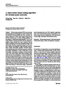
2. Relate works According to the existing research [2]~[4], we could classify the architecture of WSNs into two categories, one is flat architectures [5][6], the other is cubic architecture (namely cluster based architecture) [7]~[9]. So called flat architectures are composed by homogeneous sensor nodes, which have the following properties: (1) The position of each sensor node in WSNs is equal, (2) A sensor node could only communicate with its neighbors which are in the range of its transmission power, (3) It support QoS, that is there is more than one paths between the source and sink node, As in figure 1, there are two paths between sensor node 1 and sink node (e.g. 1→3→4→8→Sink and 1→3→4→7→8→Sink). (4) There is no bottle neck factor to be taken into consideration. The shortcoming of flat architectures is that they do not support the property of scalability, that is, flat architectures could not be used for a large scale sensor deployment application. Therefore, some researchers raised a cubic architecture to solve the problem of scalability [7]. In cubic architecture, at first the sensor nodes use a selection or auction scheme to select a header in a group (namely cluster), and intra-communication within a group could be processed directly between sensor nodes, however, inter-communication between groups must relay on headers as an intermediate. As in
1. Introduction Wireless sensor networks are the integration of wireless communications, micro-electro-mechanical system (MEMS), sensor techniques, and distributed computation techniques. With the development of dramatic reduction in size of sensor, WSNs will be used in a widely fields in the future. Military applications will include battlefield monitoring, targeting, nuclear, biological and chemical attack detection and reconnaissance, and so on. Civilian applications are composed of forest fire detection, biocomplexity mapping of the environment, precision agriculture, health, and transportation, etc [1]. The key difference between WSNs and Ad hoc network is that the basis role of WSNs is to sense environment, collect and transmit data to the sink node within the resource constraints, such as energy, process, and storage constraints. The main objective of Ad hoc network is how to organize sensor nodes and cooperate efficiently to complete a task. Energy constraint is a key impact of the lifetime of WSNs, but it is only a factor not the most importance in Ad hoc network. WSNs require architecture and communication protocol and algorithm to be energy-efficient, scalable, flexible and distributed. 978-0-7695-3494-7/08 $25.00 © 2008 IEEE DOI 10.1109/ISISE.2008.66
297
two architectures. Our cluster based hybrid architecture introduces multicast communication technology to solve the broadcast blast, the deployment of homogeneous and redundant sensor nodes to solve “hot spot” problem, local process and local decision to solve real time problem in WSNs. Furthermore, our architecture combines the advantages of both flat and hierarchical architecture.
figure 2, sensor node 1 in group 1 could communicate with sensor node 2 in group 2 on the condition of the help of header 1 and 2. Clearly, merits about cubic architecture are good scalability and high throughout. However, it has some drawbacks. Firstly, the header selection algorithm in a group is too complex to be used in WSNs according to the resource constraints. Secondly, there is a bottleneck element in this architecture, for example, if the header is in the state of malfunction, the sensor nodes in this group could neither communicate with the sink node nor another nodes in other groups. Thirdly, the upper layer nodes only have the role of managing the group and forwarding packet, does not have self-organizing scheme to make a local decision to meet time critical application.
3. Hybrid architecture In this section, deployment principles, multiple communication mode and local collaboration will be presented respectively .
3.1.Principles The hybrid architecture proposed here not only combines the advantages of both cluster and flat architecture, but also introduces multiple communication model (i.e. multicast, any-cast and broadcast) in order to prolong the life-time of WSNs. As in figure 3, the proposed architecture is similar to a reverse multicast tree. Arabic numerals (i.e., 0, 1, … i1, i) are assigned to layers in the tree architecture. Each layer may be composed of several groups. A group of nodes is noted G , where i is the layer the group belongs to and j is the number of the groups within the layer. Two black dotes on the either side of arc line is the range that the multicast communication of upper layer can cover. The black circle in each group is a redundant sensor node which usually is in the state of sleep. As in figure 3, the black circle beside sensor node 1 is a redundant one. Single arrow line indicates multicast communication mode, and double arrows line any-cast. We will especially explain that double line arrow stands for adopting TDMA (Time Division Multiple Access) technology to implement multiple access. The communication between sensor nodes in the group of the 0-th layer adopts broadcast communication mode, that is, the 0-th layer is a traditional flat architecture. However, the architecture from the 1-th layer to i-th layer adopts cluster based one, and the communication mode linking these two parts is any-cast. So we call this architecture is a hybrid one. 3.1.1. Heterogeneous sensor nodes. We define the ratio of the sensor nodes number at the lower layer to that at the higher layer as λ , and we call this “deployment rule” in sensor network. As for homogeneous sensor nodes in figure 3, we deploy homogeneous sensor nodes with different power lever in different layers. That is, the nearer to the sink node, the more power equipped with these nodes, for
Figure 1. Flat architecture
Figure 2. Cubic architecture
Similarly to internet, a five-layers architecture is proposed by I. F. Akyildiz[1], which is suitable to standardize the WSNs, but not practicable to real application. [10]presents an uneven clustering architecture to organize network topology, in which tentative cluster headers use uneven competition ranges to construct clusters of uneven sizes, in order to solve the problem of “hot spot”. Note that how to precisely decide the sizes of clusters near to the sink node is difficult. The ongoing MANNA architecture [11] considers three management dimensions: functional areas, management levels, and WSN functionalities. But this architecture mainly takes notice of application semantics, not consider of the details of engineering technologies. The project ANMP[12] present a protocol for managing mobile wireless networks. The protocol uses hierarchical clustering of nodes to reduce the number of messages exchanged between the manager and the agents (mobiles). Note that the author discusses the issue from network management as above [11]. Yao chung[13] proposes a scheme for Self-Organization Management Protocols of higher-level nodes to contest member nodes with multi-hop to form hierarchical clusters. Although this architecture is partially similar to that of this paper, There are some differences between these
298
cluster members is the same with sending frequency of cluster header, that is, they all have the same multicast address. However, from the 0-th layer to the 1-th layer we use any-cast communication mode to implement node redundancy and energy saving, that is, the nodes in a same cluster at 0-th layer could choose anyone of sensor nodes as their cluster header and communicate with this header. The communication mode within the nodes at 0-th layer adopts broadcast, which is similar to the concept in IP network. .
example, power in the nodes of the m-th layer is more than that of the m-1-th layer. So our architecture is adaptable to the deployment of heterogeneous sensors.
3.1.4. Local collaboration. One difference compared to typical cluster architecture is collaboration between nodes within the same group at the higher layers, because the nodes of higher layers equipped with more power have the capability to collaborate with each other. This provides a chance for nodes at the 1-th layer (or higher layers) to collaborate with each other using local information in order to make a local decision, and transmit this decision to the nodes at the 0-th layer (or lower layers). There are several advantages of this scheme. Firstly, this scheme could meet real-time application requirement to deal with emergent uncertain events happening. Secondly, making a local decision could save energy consuming by reducing the overhead communication over the upper nodes. Therefore, the architecture could be used for time critical application.
Figure 3. A cluster based hybrid architecture
3.1.2. Upper Link and down Link. Generally, there are two directions of data transmission in this hybrid architecture. One is the down direction from the higher layer to the lower layer, for example, sink node often transmits command to the nodes of the 0-th layer or 1th layer. We call this direction link as down link (i.e., dotted lines in figure 3). In fact down link is a multicast link. Note that sending frequency of the higher layer is the same with receiving frequency of the lower layer. Because the sender often is a cluster header at the higher layer and the receivers are all cluster members at the lower layer, the type of communication is one node to multiple nodes. Of course, another direction is from the lower layer to the higher layer, we call this direction link as upper link, such as double line arrows in figure 3, for example, the nodes of the 1-th layer using upper link to transmit sensing data to that of the 2-th layer using TDMA technology. In the same way, the sending frequency of sensor nodes at the lower layer is the same with receiving frequency of at the higher layer. Clearly, this communication type is multiple nodes to one, that is, the cluster header at the higher layer will collect and aggregate the messages from cluster members at the lower layer.
3.2. Deployment After a deployment phase of the heterogeneous sensor nodes in different regions (i.e., battle field, hazardous or other interest environment) the sensor network enters into initial phase. The main object of this phase is to construct a reverse multicast tree as in figure 3. For the creation of the different layers, we consider that a partition in different regions defines the different layers. This partition is defined before deployment. That is, we could consider the position of sink node as the i-th layer, the region which is nearer to the position of the sink node as the i-1-th layer, etc., until we defined the 1-th layer. The l–th could be divided into two layers (i.e., the 1-th layer and 0-th layer ). How to divide a terrain in different regions is specific for any application and is not taken in consideration in this paper. Due to deploying different number of sensor nodes equipped with different energy at different layers as described in section 3.1.1, if the number of sensor nodes deployed at 1-th layer is N, then the number of nodes at the 2-th is , and the number of nodes at the 3-th layer is , etc. Of course, the energy equipped for sensors nodes at the 2-th layer is more than that of nodes at the 1-th layer, energy of nodes at the 3-th
3.1.3 Multiple communication mode. In order to solve the problem of “broadcast blast” in broadcast communication mode, we adopts multicast communication in down links to propagate command, that is, Only members of cluster (or group) could receive the command from its header according to the concept of multicast. the upper links from the 1-th layer to the i-th layer utilize TDMA to gather sensing data. In contrast to using Class D of IP address in IP network as multicast address, we use signal frequency as multicast address in sensor network. Therefore, only cluster members could receive the command from cluster header because the receiving frequency of
299
layer to that at 2-th layer, the cluster header also need to select a time slot for every cluster member at the 1th layer respectively, and informs this information to its members. Afterwards, the nodes at the 3-th layer wake up from the state of sleep and propagate a AM packet respectively, the nodes at the 2-th layer will act as the nodes at the 1-th layer above. The rest may be deduced by analogy until sink node. Finally, a reverse multicast will be constructed as figure 3. As in figure 4, nodes at the 2-th layer first send an AM command to the nodes at the lower layer. All the nodes receiving this command construct the 1-th layer, otherwise construct the 0-th layer. The nodes at the 1th layer immediately construct different groups respectively according to coverage priority or even energy scheme. The nodes in the same group at the 1th layer select a node at the 2-th layer as their header with respect to the received signal strength of the message (AM), and inform this information to its header. The header then regulate a down frequency2 used for send command to the nodes at the 1-th layer, and receiving frequency3 used for receiving sensing data from the nodes at the 1-th layer. Next the header allocate each member a time slot used for TDMA, and inform the information including down frequency2, receiving frequency3 and time slot to its members at the 1-th layer. The nodes at 1-th layer then adjust its upper frequency3 equal to receiving frequency3 which is used for sending sensing data to its header, and adjust its receiving frequency2 equal to down frequency2 which is user for receiving command from its header. The nodes at 0-th layer also construct a group similar to the nodes at the 1-th layer, and then select a node at the 1-th layer which is the nearest to the group as its head, and regulate an upper frequency1 used for sending sensing data to its header with anyone communication mode, Then inform this information to its header at the 1-th layer. The header at the 1-th layer adjusts receiving frequency1 equal to upper frequency1 which is used for receiving sensing data from the nodes at the 0-th layer. Next the header regulates a down frequency0 used for sending command to nodes at the 0-th layer, and inform these information to nodes at the 0-th layer. The nodes at the 0-th layer then adjust their receiving frequency0 equal to down frequency0 used for receiving command from its header. After the initial phase, the sensor network enters into phase of run-time. Generally, the system is in the sate of sleep in order to save energy consuming. When user want to know the detail states of their interest regions, the sink node will multicast a command to the nodes at the (i-1)-th layer. Of course, the nodes at the (i-1)-th layer will multicast the same command to the nodes at the (i-2)-th layer, in turn, until the nodes at the 1-th layer and 0-th layer receive the command. Next
layer is more than that of nodes at the 2-th layer. That is, the nearer to the sink node, the greater is the power of these nodes. At first, the nodes at the 2-th layer propagate a AM (announcing message) packet respectively, however, the nodes from the 3-th to the i-th layer are in the state of silence (or sleep), the other nodes that could receive AM belong to the 1-th layer, otherwise are part of the 0-th layer. We call nodes attributed to the 0-th layer as orphan nodes because they could not communicate with nodes at the 2-th layer directly. Then the nodes at the 0-th layer could use traditional protocol, such as coverage priority or even energy scheme to construct different groups respectively. The nodes in group of the 0-th layer use broadcast to communicate with each other within the same group, only the node in each group which is the nearest to nodes at the 1-th layer has the right to use anycast to communicate with any one node at the 1-th layer. Nodes in different group at the 0-th layer could not communicate with each other directly, that is, this communication must rely on nodes at the 1-th layer as intermediates to transfer. The nodes at the 1-th layer could use the same scheme as nodes at the 0-th layer to be partitioned into different groups. According to the received signal strength of the message (AM), the nodes in the same group at the 1-th layer select a node at the 2-th layer as their header. Maybe is there a strange phenomenon
Figure 4. UML sequence diagram of deployment
that group at the 1-th layer select more than one headers at the 2-th layer, Our strategy is that only one header is active, the other headers as redundant headers.( as the black circle at the 2-th layer). are all in the state of sleep. The redundant header communicates with active header in the same group by heart-beat message, Next the active header at the 2-th layer regulates not only a down frequency used for multicast a command to its cluster members at the lower layer, but also a receiving frequency used for receiving the message from its cluster members, and then informs these two frequencies to the nodes of the same group at the 1-th layer. Because of adopting TDMA communication mode from the the nodes at the 1-th
300
the nodes at the 0-th layer will use any-cast to transmit sensing data to any one node at the 1-th layer. The nodes at the 1-th layer at first aggregate all the data including the data both being received from the 0-th layer and sensing the environment by itself, then using TDMA to transmit the data aggregated to upper headers until sink node receive user’s interest data.
4.2. Temporal complexity analysis In this paper, we use the number of hops as delay time metric, because the energy consuming in transmission occupies the more proportion in contrast to that in instruction process. In the rest section, we will analyze the number of hops in the initial phase and run-time phase respectively, and get the total number of hops. In the initial phase, the nodes at the 2-th layer at first propagate a AM packet to the lower layers, at the same time the nodes at the 1-th layer use one hop to inform the selected header, and then the header at the 2-th layer uses one hop inform the node in the same group at the 1-th layer down frequency and receiving frequency. During this process of interaction, our hybrid architecture use only three hops. And the nodes at the 3-th layer propagate the same AM packet to the nodes at the 2-th layer, we can use the same method to analyze the number of hops in this process. Finally, we could use formula (3) to get the total hops during initial phase if we neglect the multi-hops at the 0-th layer and hops for creating different group in each layers, because the number of sensor nodes at the 0-th layer is fewer which are out of the range of the sensor nodes at the 2-th layer. S hops−initial = 3 × (i − 1)
4. Performance analysis In this section, we will analyze the performance of our cluster based hybrid architecture with a view to quantity analysis and quality analysis. Quantity analysis consists of two aspects, i.e., temporal complexity and spatial complexity analysis.
4.1. Spatial complexity analysis. On the assumption that we deploy heterogeneous sensor nodes according to the “deployment rule”. That is, if the number of the nodes at the 0-th and 1-th layer is N, then the number of nodes at the 2-th layer is
λN
, in turn to higher layer, the number is λ N …… 1 i − 2 , 1 (= 1) . Afterwards we could get the number i −1 λ
2
λ
of all sensor nodes in the reverse multicast tree as formula (1).
a (1 − λ ) ( (1 − λ ) a i
S
i
=
=
1
1
a −λa 1
(3)
Where i denotes the number of layers .
= 1, ai = N )
In the run-time phase, sink node multicast a command to the nodes at the i-1-th layer, in turn to i-2, i-3, ……, until the nodes at the 0-th layer receive the command, the sum of hops is i. And then the nodes at the 0-th layer use one hop to any-cast the data to the 1th layer, if we neglect the multi-hops at the 0-th layer. Afterwards, the nodes at the 1-th layer use TDMA to transmit the data to the 2-th layer, that is , the nodes at the 1-th layer will transmit a packet to upper headers during their own time slots. If we combine the 0-th layer and the1-th layer as the same layer, then we can calculate the sum of hops in run-time phase as formula (4), considering the number of sensor nodes of each group in different layers as in figure 3 following the “deployment rule”.
i
1− λ
= Ο(N )
(1)
Because the number of sensor nodes at the 0-th and 1-th layer is N, so we could get the number of sensor nodes from the 2-th layer to the i-th layer as formula (2).
S=
s −N i
N −1 = λ −1 = Ο(N )
(2)
S
Relative to the homogeneous nodes at the 0-th and 1-th layer, we could see the heterogeneous sensors nodes from the 2-th layer to the i-th layer as sink nodes. So our hybrid architecture is actually a multiple sink nodes sensor network, the number of sink nodes is as the result of formula (2). According to formula (2), the spatial complexity increases linearly to the number of sensor nodes at the 0-th and 1-th layer (N) in our cluster based hybrid architecture as formula (1).
hops− runtime
= i + Si −1
a (1 − λ ) − 1( a 1− λ i
=i+
=i+
1
1
λN − 1 −1 λ −1
= 1)
(4)
Finally, sum of hops during the two phases is as formula (5). S hops = S hops −initial + S hops−runtime = 4(i − 1) +
λN − 1 λ −1
= Ο (i ) + Ο ( N )
301
(5)
[5] F. Ye, A. Chen, S. Liu, and L. Zhang, “A Scalable Solution to Minimum Cost Forwarding in Large Sensor Networks,” in Proc. Of the 10th International Conf. on Computer Communications and Networks, 2001, pp. 304–309 [6] K. Sohrabi, J. Gao, V. Ailawadhi, and G. Pottie, “Protocols for Selforganization of A Wireless Sensor Network,” IEEE Personal Communications, vol. 7, Issue 5, pp. 16–27, 2000 [7] S. Lindsey and C. Raghavendra, “PEGASIS:Power-Efficient Gathering in Sensor Information Systems,” in International Conf. on Communications, 2001 [8] A. Manjeshwar and D. Agrawal, “TEEN: a Routing Protocol for Enhanced Efficiency in Wireless Sensor Networks,” in International Proc. of the 15th Parallel and Distributed Processing Symposium, 2001, pp. 2009–2015 [9] W. Heinzelman, A. Chandrakasan, and H. Balakrishnan,“Energyefficient Communication Protocol for Wireless Micro Sensor Networks,” in Proc. of the 33rd Annual Hawaii International Conf. on System Sciences, 2000, pp. 3005–3014 [10] Li Chengfa, Chen Guihai et al. An uneven cluster-based routing protocol for wireless sensor network, Chinese journal of computers, Vol 30, No 1, January, 2007 [11] Wenli Chen, N.J., Suresh Singh, ANMP: Ad hoc network Network Management Protocol. IEEE Journal on Selected Areas in Communications, 1999. 17(8): pp. 1506- 1531 [12] W. Heinzelman, J. Kulik, and H.Balakrishnan, “Negotiation-based Protocols for Disseminating Information in Wireless Sensor Networks,” in Proc. of the 5th Annual ACM/IEEE International Conf. on Mobile Computing and Networking, 1999 [13] Yao-Chung Chang, Z.-S.L., Jiann-Liang Chen, Cluster Based SelfOrganization Management Protocols for Wireless Sensor Networks.IEEE Transactions on Consumer Electronics, 2006. 52(1): pp. 75-80
According to formula (5), delay time increases linearly to i (the number of layers) and N (the number of sensor nodes at the 0-th layer and the1-th layer) in our reverse multicast tree as figure 3. Therefore, the hybrid architecture in this paper adapts to large scale sensor network. Note that during my temporal complexity analysis, parallel communication mode (i.e. the upper headers multicast parallel to their own group at the lower layer) be deemed as only one hop, because not only the cluster header could use only one hop to propagate a command to their cluster members at lower layer, but also all the transmission of different cluster headers at the same higher layer is parallel. However, we take into consideration sequential communications (i.e. the nodes in lower layer use TDMA to transmit data to their header in higher layer) for its impact of the delay time. Because different groups in the same layer using TDMA technology is a simultaneous action, we need only to take into account one group’s impact on the delay time.
5. Conclusion and future works In this paper, we propose a cluster based hybrid architecture for large scale sensor network, which use multiple communication modes and deployment of heterogeneous sensor nodes to solve the problems of “broadcast blast” and “hot spot” respectively. Our future researches will focus on some detail technologies, such as data aggregation, coverage optimization based on the hybrid architecture and making a decision about which λ is the best choice through simulation. Especially, we will use the theory of Holonic Multi-Agent Systems to formalize this a decision about which λ is the best choice through simulation. Especially, we will use the theory of Holonic Multi-Agent Systems to formalize this architecture and verify its validation for some properties, i.e., scalability, long lifetime and robustness.
6. References [1] I.F.Akyildiz, W.Su, Y.Sankarasubramaniam, E.Cayir-aci, wireless sensor network : a survey. Computer networks 38, pp. 393-422, 2002 [2] F. Ye, H. Luo, J. Cheng, S. Lu, and L.Zhang, “A Two-tier Data Dissemination Model for Large-scale Wireless Sensor Networks,” in Proc. of the 8th Annual International Conf. on Mobile computing And networking. Atlanta, Georgia, USA: ACM Press, September 2002, pp. 148– 159 [3] Zhigang Li, Xingshe Zhou, Shining Li, Gang Liu, Kejun Du. Issues of Wireless Sensor Network Management. Embedded Software and Systems , Volume 3605/2005, pp. 355-361, 2005 [4] N. Xu, S. Rangwala, K.K. Chintalapudi, D. Ganesan, A. Broad, R. Govindan and D. Estrin, “A Wireless Sensor Network for Structural Monitoring,” ACM SenSys’04, Baltimore, Maryland, USA, November 2004.
302