A Code Generation Framework for Time-Triggered Real-Time Systems Johannes Pletzer, Josef Templ, Wolfgang Pree C. Doppler Laboratory Embedded Software Systems University of Salzburg Salzburg, Austria
[email protected] Abstract—We propose ttCodeGen, a flexible code generation framework for potentially distributed, time-triggered real-time systems. It is designed for developing systems based on the Logical Execution Time (LET) programming paradigm which enables the platform independent description of the timing behavior of such systems. The ttCodeGen framework covers both code generation on node level as well as the generation of a communication schedule for the bus connecting the nodes. For that purpose task and communication schedules must be generated. Those schedules influence each other and consequently our framework deals with their interdependence. The framework is extensible by the use of plug-ins, which are used to support specific node platforms and communication protocols and therefore guarantee a clear separation of platform independent from platform dependent concerns. We present the plug-in interfaces and describe sample plug-ins we developed for the FlexRay communication bus using two hardware platforms with FlexRay controllers. Keywords-framework; code generation; platform abstraction; logical execution time; scheduling
I.
PLATFORM ABSTRACTION AS BASIS FOR CODE GENERATION
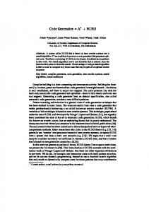
Embedded software is usually platform dependent and not compositional, especially when it comes to its timing properties. This leads to increased efforts required for integration, validation and maintenance. The timing behavior is typically not specified explicitly but rather is a result of the system load and the occurrence of sometimes unpredictable events at runtime. The concept of the Logical Execution Time (LET) introduced in the realm of the Giotto project [1] aims to overcome this shortcoming by abstracting from the physical execution time of tasks and, in the distributed case, from network communication. The LET abstraction specifies that the inputs of a task, which can be values read from sensors or outputs of other tasks, are read at the beginning of the LET period and the outputs provided to other tasks or actuators are only updated at the end of a task’s LET. As shown in Fig. 1 the beginning of the LET is called the release event whereas its end is called the terminate event. As long as physical task execution at runtime and potential network communication take place
Figure 1. Logical Execution Time (LET)
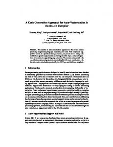
within the LET of a task, the software will exhibit exactly the same observable behavior on any platform - no matter if it is fast, slow or even distributed. Fig. 2 illustrates the interaction between two LET-based components called Sender and Receiver. Sender contains a task task1 with a LET of 5 ms and Receiver runs a task task2 with a LET of 10 ms. In this example, task2 receives the output value of task1. The vertical arrows indicate when the results of task1 are communicated to task2, which is exactly at the terminate event at the end of task1’s LET. The value is then available for task2 at its release event at the start of its next LET period. The basic idea of handling network communication in LET-based systems is that the time it takes to communicate over a network is also accounted for in the LET of the producer task. This leads to the notion of transparent distribution [2] as the fact that a system is distributed does not change its observable behavior, though the physical behavior, in particular the order and length of task executions LET 5 ms
Sender Sender
task1
task1
task1
task1
communication of task1’s output to task2
Receiver Receiver
task2
task2
LET 10 ms
Figure 2. Communication between LET components
t
communication window
communication window
LET 5 ms
Sender Sender
task1
task1
task1
task1
node1
t local buffer
communication bus local buffer
Receiver Receiver
task2
task2
node2 LET 10 ms
Figure 3. Communication window example
and the time when messages are communicated, may differ. Fig. 3 depicts the same example as Fig. 2 above but also indicates the physical timing assuming that Sender and Receiver execute on a distributed system. The Sender component is executed on node node1 and the Receiver on node node2 which are both connected to a communication bus. The shaded blocks indicate the physical execution of the tasks on a node’s CPU. In such a setup the output of task1 needs to be transferred via the bus. The communication window for doing so spans from the end of a task’s physical execution time to the terminate event at the end of its LET. As long as the network communication takes places within this window the system shows exactly the behavior specified by the LET semantics. Code generation for distributed embedded systems using the LET abstraction is based on the idea of having software components with specified timing properties which serve as a unit of distribution and run in parallel on one or more nodes. Typically a graphical front-end harnessing our code generation framework eases the deployment of such components to a distributed system. Such a tool, as presented in [12], for example also provides configuration options concerning the mapping of sensors and actuators to concrete hardware devices and other hardware specific properties that are required for successful code generation. We use the Timing Definition Language (TDL) [11] as a sample LET-based language. Code generation is based on TDL modules. The TDL compiler generates so called ECode for every module which encodes the timing information, that is, the time when tasks must be released and when sensors and actuators must be read and written, for the TDL runtime system. The functionality code, which implements the actual functionality of a TDL module, is provided separately. The code generated by our framework—also called glue code— consists of all code that is needed to execute TDL components on a specific, potentially distributed platform. Depending on the target platform this might for example include task dispatch tables, operating system configuration files and driver code for sensors and actuators. In the following we introduce the ttCodeGen framework in two steps. We go from a single node system to a system with multiple interconnected nodes including communication system scheduling. The presentation is deliberately on an abstract level as the focus of this work is on the interactions
of all required software components and on a clear separation of platform-dependent and platform independent concerns in order to form a solid basis for systematic extension and code reuse. For details such as how the communication schedule is constructed please refer to our previous work which is cited at the corresponding text passages. II.
CODE GENERATION FOR A SINGLE NODE
We start with our description of the framework with the code generation facilities required for a single node system. The challenge is to generate code for a variety of different hardware platforms. The design goal was to come up with a flexible architecture that allows maximum code reuse when adding support for additional hardware targets. We decided to use repeated subclassing to achieve this. The degree of platform dependence increases with every additional inheritance level in the class hierarchy. The subclassing approach enables a subclass to reuse code generation functionality code from its ancestor but also to suppress or modify parts of it. Fig. 4 illustrates the single node structure by means of a class diagram. AbstractNodePlatform is on top of our class hierarchy. It contains methods that must be implemented by every class that generates code for a specific platform, most notably a method that defines which TDL modules a node must execute, a schedulability check method which is used to test if those modules are schedulable on a node and a method that triggers the actual code generation. Furthermore it provides an interface for the configuration of platform specific I/O devices which may be used to allow configuration via a graphical user interface. Next in the hierarchy is a class called CPlatform which implements code generation functionality for all platforms that use the C programming language. It generates C glue code which enables the execution of TDL components by the TDL runtime system. EmbeddedCPlatform aims at embedded systems with simple operating systems which typically lack a file system and therefore the TDL ECode is represented as abstract class AbstractNodePlatform setModules() isSchedulable() emitCode() extends abstract class CPlatform
class RTLinuxPlatform
Abstract platform
Programming language
abstract class EmbeddedCPlatform
class OSEKPlatform
Operating system & common features
Concrete hardware platforms
Figure 4. Node platform abstraction levels
C code, which is compiled and linked to the executable for the particular node. It also adds task scheduling and the generation of dispatch tables for task execution. RTLinuxPlatform generates code for RT Linux [3] which provides a file system and therefore extends CPlatform directly. On the next inheritance level we have OSEKPlatform generating code for the OSEK/VDX [4] operating system and additional classes which implement common code generation features of multiple hardware platforms. The last level, indicated by empty boxes in Fig. 4, consists of platform specific plug-ins that are tailored to concrete hardware platforms and are discussed below. When adding support for any additional programming language, operating system or hardware platform, one simply has to pick the appropriate level in the class hierarchy and add the specific classes that generate the corresponding code. III.
COMMUNICATION SCHEDULE GENERATION FOR A DISTRIBUTED SYSTEM
A system with multiple nodes is typically a distributed system where nodes are connected via some sort of communication bus. To allow different communication protocols to be combined with our node platforms we introduce the notion of a communication layer. Fig. 5 depicts a selection of the platform classes from Fig. 4 along with their associated communication layer interfaces. In analogy to the platform classes repeated subclassing is also performed with the communication layer interfaces. Every platform uses a class that implements a communication layer interface which is responsible for the generation of the code needed to interact with other nodes via a communication bus. Typically there are at least two implementations of this interface: A trivial one for standalone nodes not connected to a communication system at all and one or more that implement a concrete communication protocol. Implementation of the CCommLayer and EmbeddedCCommLayer interfaces handle the packing and unpacking of TDL ports independently of the communication system actually used. Additional layers then add communication bus specific functionality and handle code generation for specific communication controllers used by a hardware platform. Adding communication capabilities for every node can be sufficient for event-triggered communication protocols such as Ethernet or CAN. Time-triggered protocols such as TTP or FlexRay [5] however require a global abstract class AbstractNodePlatform
uses
interface CommLayer
extends abstract class CPlatform
interface CCommLayer
abstract class EmbeddedCPlatform
interface EmbeddedCCommLayer
Figure 5. Communication layer class diagram
Figure 6. Framework collaboration diagram
communication schedule for its operation. Usually such a schedule is created manually as it is difficult to automatically extract the scheduling requirements of arbitrary systems. LET-based systems however describe the data flow and timing requirements of their components explicitly and consequently it is feasible to perform automatic bus scheduling [2, 7]. Optimizations of such scheduling algorithms have also been proposed [6]. The special benefit of our code generation framework is that it clearly separates the platform independent scheduling tasks that need to be performed for every LET-based system from those which are specific for concrete bus architectures. The reason for doing so is to specify what is needed to implement such a scheduler for any given bus protocol. In analogy to the node platform architecture, we also use plug-ins for adding support for different communication platforms. Fig. 6 presents an overview of how the communication scheduling part of our framework interacts with the node platform parts described above. In the figure those two parts are labeled communication level and node level. The numbers indicate the order in which the depicted steps are performed. As basis for code generation LET-based components and their deployment, specifying which component is executed on which node, are required. This information is used by the platform independent frame generator to generate a list of frames that must be transferred between nodes. The node plug-in however needs the deployment information to generate the appropriate code that executes the components deployed on a node. Node plug-ins are split into a platform independent general part and a platform dependent subclass of it implementing a concrete hardware target as described above. The frame scheduler plug-in is the platform dependent part of the communication level and is tailored to a specific communication protocol. It schedules the frames obtained by the frame generator and assigns a concrete timing to them which must be within the timing windows given for each frame by the frame generator. The frame scheduler can query the node plug-in by supplying it with a candidate set of frames with assigned timing to check whether the nodes are schedulable with this
set. If it is not schedulable the frame scheduler plug-in can come up with an alternative set which is schedulable. This approach prevents that a communication schedules is produced that eventually is not usable because of restrictions imposed by node scheduling constraints and is a key improvement over the algorithms proposed in [2, 6, 7]. After a feasible schedule is found it is stored in a data structure called Comm Schedule by the frame generator which is subsequently used by the node platform to generate code. This code typically includes configuration files for a LETbased runtime system which guarantees the timing specification is executed correctly by ensuring that sensor readings, actuator settings and task invocations are performed at the specified time instants. A. Frame Generator The frame generator is platform-independent and essentially analyzes the communication required between all TDL modules in the system according to their node assignments. As shown in Fig. 3 for every task that needs to transmit a message on the bus there is a communication window for doing so inside its LET period. The frame generator computes all those windows and generates a list of messages that need to be transferred between nodes and determines for every message a release time and a deadline. Communication period. We calculate a suitable communication period, which we call the period after the communication pattern is repeated. This calculation depends on the details of the concrete LET-based system used. In general the communication period is computed by searching for a repeating pattern in the list of messages. As the resulting period may be unsuitable for the specific bus protocol used, the frame scheduler plug-in may refine it by dividing it by an integer number. Communication frame windows. Out of the list of messages the frame generator computes a list of frames that must be transferred between nodes. Frames are a container for messages and have a size, a release and deadline constraint, a sender and a list of receiver nodes. The frame window is the period between the release time and the deadline of a frame. The frame generator assigns messages with the same sender and similar release time and deadlines to the same frame while trying to minimize the number of frames that are generated. The algorithm is explained in detail in [2, 6, 7]. As the frame windows obtained are not unique for a given number of messages, our implementation is improved in comparison to ones referenced above as we do not only generate a single set of frame windows but instead iterate over multiple sets, making it more likely to find a feasible schedule. Communication schedule. After the scheduling constraints of the frames have been identified it is the frame scheduler plug-in’s task to determine the specific start and end time for every frame. Based on this information the frame generator outputs a generic communication schedule containing information about nodes, frames, messages, tasks and task ports. This data structure is important for subsequent code generation for individual nodes.
B. Frame Scheduler Plug-In The frame scheduler is platform specific and must be implemented for a concrete communication protocol. As outlined above, the frame scheduler serves two purposes: It potentially alters the suggested communication period and sets the frame start and end times so that they respect the properties of the underlying bus protocol. Frame scheduling. The frame generator supplies for every frame a window in which it must be scheduled. Note that however it does make a difference where exactly in this window a frame is scheduled. The start of this window is only a best-case estimate and it is not guaranteed that the whole system, including tasks on nodes, is schedulable if frames are actually scheduled at the beginning of this window as this might constrain the task scheduler too much so that no valid task schedule can be found. Therefore we require the frame scheduler plug-in to schedule all frames as late as possible. The transmission time of a frame depends on bus specifics such as the bus speed and timing properties such as inter-frame gaps. All these requirements must be taken into account for calculating correct frame start and end times. The frame scheduler also can merge frames if their timing requirements are compatible and they have the same sender. The frame scheduler plug-in is provided with an interface to check whether the calculated start and end times for frames lead to a feasible schedules on node level. This is a key feature of our framework as it takes into account the interdependence of communication and node task schedules and thus prevents the whole code generation process from running into a dead end by creating a communication schedule for which not all nodes are able to come up with an appropriate task schedule. IV.
TTCODEGEN ADAPTATION FOR FLEXRAY
We developed sample plug-ins which generate code for TDL components that execute on prototyping hardware using the FlexRay communication bus. FlexRay [5] is a time-triggered TDMA communication protocol intended for automotive applications. It operates at a speed of 10 MBit/s and thus is significantly faster than current automotive networks such as CAN and LIN. It has a fixed length cycle period which repeats itself and is divided into a static and a dynamic segment. The static segment, representing the timetriggered aspect of FlexRay, consists of equally sized communication slots each being statically assigned to a specific node in the cluster for sending. The dynamic segment of a FlexRay cycle is optional and can be used dynamically by different nodes at runtime. FlexRay uses dedicated communication controllers that need to be configured with a set of global cluster parameters and local node parameters. The controller handles all network tasks including startup and time synchronization and provides message buffers as interface to the host CPU. By using our framework we are able to automatically generate a fully functional FlexRay system that runs arbitrary TDL components. The only requirement is that both CPU
power and network bandwidth are sufficient – otherwise no code is generated. A. Node Plug-Ins Fig. 7 shows a class diagram depicting plug-ins we developed for our framework to support certain FlexRay hardware. EmbeddedCPlatform can also be found in Fig. 4 above. FlexrayNodePlatform contains some common code generation features required for all FlexRay based platforms. NodeRenesasPlatform and MicroAutoBoxPlatform are tailored to concrete FlexRay hardware platforms including their operating systems, compilation environments, I/O port drivers and communication controllers. Fig. 8 shows the class hierarchy structure of the NodeRenesasPlatform node platform which implements a plug-in for a NODE prototyping board manufactured by DECOMSYS which is equipped with a Renesas M32C CPU and a Bosch E-Ray FlexRay controller and runs a simple operating system called AES (Application Execution System). In addition to Fig. 7, Fig. 8 also shows the communication layer interfaces of all platform classes relevant to NodeRenesasPlatform. In the case of EmbeddedCPlatform this interface is called EmbeddedCCommLayer and it has two implementations: StandaloneEmbeddedCCommLayer is a trivial implementation used for standalone nodes that are not connected to a communication bus whereas StandardEmbeddedCCommLayer imlements basic communication functionality regarding the transportation of TDL port values across the network which is independent of the concrete communication platform. A class implementing FlexrayCommLayer then adds code which is specific to the FlexRay communication protocol but still independent of the concrete FlexRay controller used. Finally a NodeRenesasCommLayer implementation generates all the appropriate code to configure the Bosch E-Ray FlexRay controller used on our prototyping board. MicroAutoBoxPlatform is similar to NodeRenesasPlatform but generates code for a dSPACE MicroAutoBox 1401/1505/1507 which is commonly used in the automotive industry for prototyping purposes. It uses another type of FlexRay controller which requires a different configuration format and buffer handling. B. Communication Scheduling Plug-In For our prototyping environment we developed a frame scheduler plug-in for the time-triggered FlexRay protocol. abstract class EmbeddedCPlatform extends abstract class FlexrayNodePlatform
class NodeRenesasPlatform
class MicroAutoBoxPlatform
Figure 7. FlexRay node platforms class diagram.
abstract class EmbeddedCPlatform
uses
interface EmbeddedCCommLayer
extends abstract class FlexrayNodePlatform
interface FlexrayCommLayer
class NodeRenesasPlatform
interface NodeRenesasCommLayer
Figure 8. NodeRenesasPlatform class diagram
Communication period. FlexRay has a restriction for the maximum length of the cycle period of 16000 macroticks, where a macrotick can be configured to last between 1 and 6 µs. If the suggested communication period exceeds this value it is divided by an integer so that the resulting cycle period is within this limit. Slot size and frame assignment algorithm. Our FlexRay frame scheduler plug-in optimizes for minimal bandwidth usage on the FlexRay bus. There is a trade-off between a large static slot size (note that all static slots have equal size) that minimizes overhead but might waste bandwidth by having small TDL frames occupy a complete FlexRay slot and having a small static slot size that introduces a large overhead as the overhead increases with more slots. The lower limit for the slot size is the size of the largest frame as we currently do not support splitting a frame across multiple slots. The maximum size is the maximum slot size allowed by the FlexRay specification, which are 127 2-byte-words. The algorithm works as follows: First the frames obtained from the frame generator are sorted using a reversed EDF (earliest deadline first) algorithm, which simply means that they are sorted by decreasing deadline time, i.e. the frame with the latest deadline is first. Then for all relevant slot sizes it is searched for a valid frame to FlexRay slot mapping. This is done by mapping every frame from the sorted list of frames to the latest FlexRay slot still available. Of all possible static slot sizes the one which leads to a valid mapping and produces the FlexRay schedule with minimal bandwidth usage is selected. FlexRay parameter calculation. FlexRay has about 30 global cluster parameters that need to be set in order to obtain a working configuration. The FlexRay specification [13] describes those parameters including the constraints they must fulfill. The design goal for our FlexRay implementation of the frame scheduler plug-in was that the user should not be bothered with FlexRay details and consequently we assumed worst case values for some parameters and then applied the constraints to compute a valid parameter set. This is feasible for prototyping purposes as it speeds up the development process but we are aware that for series production it is required to be able to alter some parameters to tailor it to specific requirements such as the maximization of bus throughput or the hardware used. FlexRay startup. The FlexRay communication protocol requires that exactly two or three nodes are configured as socalled cold start nodes. These nodes send special start up
frames in the sending slots assigned to them and initiate the FlexRay communication cycle. The plug-in for FlexRay therefore has to ensure that all requirements for successful startup are fulfilled. Whether a node is a cold start node or not is specified via a property by the user. The plug-in checks the number of cold start nodes in the cluster and automatically assigns them a sending slot which is then configured to be used for the startup frames. V.
RELATED WORK
The feasibility of automatic scheduling for LET-based systems has been demonstrated before. In [2] the notion of transparent distribution is proposed and a prototype implementation is presented. However it is tailored to a specific bus protocol, namely CAN, and is not designed in a way so that is allows for easy adaptation to other protocols. Also there is no clear separation between what we call the frame generator and the frame scheduler in our work. In [6] this separation is improved, but still there is no clean and powerful enough interface specified which we think is the key to separating platform-dependent from platformindependent concerns. There are numerous commercial FlexRay design tools available. The DaVinci Network Designer FlexRay [9] by Vector is a typical example of such a tool. It helps the user to configure FlexRay by enforcing the constraints and providing an editor for schedule generation but does not provide any automatic scheduling. The TTXPlan tool [10] by TTAutomotive is able to automatically map signals to FlexRay frames. This function corresponds in part to what our frame scheduler does, but we go a significant step further by the automatic determination of the contents of the frames (i.e. the signals) based on the underlying tasks and their LET periods. Furthermore it should be noted that when using our framework there is always the possibility to switch to another network protocol easily as in such a case the whole schedule is simply regenerated to fit the new protocol when a corresponding frame scheduler plug-in is provided. Code generation for distributed Giotto systems has been proposed in [8]. The authors also use the basic idea of handling network communication by scheduling messages within the LET period of its producers. However they employ a different workflow as they require that a system integrator assigns CPU time and network bandwidth before individual components are designed. The benefit of this strategy is that code can then be generated independently. In contrast, our centralized code generation process allows more flexibility in case components are added or changed during development as then the whole code including the
communication schedule is regenerated to accommodate for all changes in the timing requirements. VI.
CONCLUSION AND FUTURE WORK
The ttCodeGen framework is a further contribution towards a comprehensive, flexible, and platform independent modeling tool chain for time-triggered real-time systems that enables easy adoption to support any additional communication and node infrastructure. Planned future work consists of adding support for additional hardware targets and communication protocols in order to test ttCodeGen’s flexibility and also to get hints on how the framework can be further improved. Furthermore we will investigate the use of genetic algorithms for communication scheduling which is likely to speed up the scheduling process and also might find feasible schedules when our current implementation does not. REFERENCES [1]
[2]
[3]
[4] [5]
[6] [7]
[8] [9] [10] [11] [12]
[13]
T.A. Henzinger, B. Horowitz, and C.M. Kirsch, “GIOTTO: A TimeTriggered Language for Embedded Programming,” Proc. IEEE 91 (2003) 84–99 E. Farcas, C. Farcas, W. Pree, and J. Templ, “Transparent Distribution of Real-Time Components Based on Logical Execution Time,” LCTES, Chicago, Illinois, 2005. V. Yodaiken and M. Barabanov, “A Real-Time Linux,” In Proc. of the Linux Applications Development and Deployment Conference (USELINUX), Anaheim, CA, January 1997. OSEK/VDX. Operating System, Version 2.2.3, 2005. R. Makowitz and C. Temple, “FlexRay - A Communication Network for Automotive Control Systems,” Proceedings of 2006 IEEE International Workshop on Factory Communication Systems, pp. 207–212, 2006. E. Farcas and W. Pree, “Hyperperiod Bus Scheduling and Optimizations for TDL Components,” ETFA, 2007, Patras, Greece. E. Farcas, W. Pree, and J. Templ, “Bus Scheduling for TDL Components,” Dagstuhl Conference on Architecting Systems with Trustworthy Components, May 2006. T. A. Henzinger, C. M. Kirsch, and S. Matic, “Composable Code Generation for Distributed Giotto,” LCTES, 2005. Vector - DaVinci Network Designer FlexRay, http://www.vectorworldwide.com. TTTech Automotive - TTX-Plan, http://ttautomotive.com. J. Templ. “Timing Definition Language (TDL) Specification 1.5,” Technical Report, University of Salzburg, 2008. A. Naderlinger, J. Pletzer, W. Pree, and J. Templ, “Model-Driven Development of FlexRay-Based Systems with the Timing Definition Language (TDL),” Proceedings of the 4th International Workshop on Software Engineering for Automotive Systems, 2007. FlexRay Communications System Protocol Specification, Version 2.1, Revision A, available at http://www.flexray.com.