design stage, but travel time and costs, and other well-known inconveniences, prohibit .... features are a rib-slot and a pin-hole connection feature. A component ...
Rafael Bidarra* Niels Kranendonk Alex Noort Willem F. Bronsvoort Faculty of Information Technology and Systems Delft University of Technology Mekelweg 4, NL-2628 CD Delft, The Netherlands http://graphics.tudelft.nl (Bidarra/Noort/Bronsvoort)@its.tudelft.nl
1
A Collaborative Framework for Integrated Part and Assembly Modeling An ideal product modeling system should support both part modeling and assembly modeling, instead of just either of them as is the case in most current CAD systems. A good basis for such integration is multiple-view feature modeling, as it allows focusing on different aspects of the product, while at the same time maintaining consistency of all model views. This paper presents a framework that supports synchronous collaborative sessions via Internet, among members of a distributed development team, with such a modeling system. The framework provides facilities for creating a hierarchical product structure, with single and compound components, and meanwhile assigning tasks to team members. The actual design of a single component is supported by a web-client specialized in part design, whereas the specification of assembly relations among components is supported by a web-client specialized in assembly design. All clients make use of the same server, which runs a multiple-view feature modeling system and maintains the complete product model, guaranteeing consistency of the part design and the assembly design views. 关DOI: 10.1115/1.1555647兴
Introduction
Current modeling systems adequately support either modeling of parts or modeling of assemblies, usually by a single user only. In particular for complex products, this leads to a lot of undesirable exchange of product data, back and forth, between different users and systems. Future modeling systems should therefore support integrated modeling of parts and assemblies by a team of development engineers. Multiple-view feature modeling is a good basis for integrated modeling of parts and assemblies 关1兴. It offers different views on a product for parts and assemblies, each view containing a specific feature model. For each part, there is a part detail design view, describing the part in terms of design form features, and a part manufacturing planning view, describing the part in terms of manufacturing form features. In addition, there is an assembly design view for the whole product, describing one or more assemblies in terms of components and connection features between these components. The part and assembly views are kept consistent, i.e. changes in one view on a part are propagated to the other view on the part, but also to the assembly design view, and changes in the assembly design view are propagated to the part views that are involved. In this way, real integration of part and assembly modeling is achieved. The approach to integrated modeling just described can be very helpful to a single engineer who is responsible for the development of a complete product. In practice, however, usually several engineers are involved in the development of a product 关2兴. This is obvious for complex products consisting of many parts, but can even be the case for relatively simple products. In both cases, one can think of different experts for the design of the parts, the manufacturing planning of the parts, and the assembly design of the complete product. Indeed, product development teams nowadays involve more and more engineers. Three essential characteristics of the working procedure of such teams can be summarized as follows:
• team members, often geographically distributed, need to work on 共at least part of兲 the same product data; • due to outsourcing of some components, team members may even be scattered over different companies, each one with its own design practice, CAD tools and data formats, further complicating the previous aspect; • collaboration among team members plays an increasingly important role in solving design conflicts as early as possible in the design stage, but travel time and costs, and other well-known inconveniences, prohibit frequent physical meetings. Due to their interdependencies, effectively supporting these characteristics cannot be achieved by three separate, independent solutions. Instead, synchronous collaborative modeling sessions via Internet are gaining attractiveness, as they indeed allow several team members to remotely coordinate their design work and discuss design issues of mutual relevance. However, systems that support real collaborative design of parts or of assemblies are hardly available, let alone systems that support collaborative, integrated design of parts and assemblies. In this paper, a collaborative framework is presented that does support integrated design of parts and assemblies. It enables members of a product development team to have synchronous collaborative modeling sessions via Internet. There are specialized webclients for part detail design and part manufacturing planning, and for assembly design. All clients make use of the same server, which runs a multiple-view feature modeling system, and takes care of all communication. The paper focuses on the top-down product structuring and task assignment and on the actual bottom-up collaborative part and assembly modeling. Section 2 summarizes the underlying approach to integrated part and assembly modeling. Section 3 discusses the state of the art in collaborative modeling and introduces the new collaborative framework. Section 4 elaborates the product structuring and task assignment, and Sec. 5 the collaborative part and assembly modeling. Section 6 describes an example of a modeling session using the framework. Section 7 presents some conclusions.
2 *Corresponding author, Phone: 31 15 278 4564; Fax: 31 15 278 7141 Contributed by the Computer Aided Product Development 共CAPD兲 Committee for publication in the JOURNAL OF COMPUTING AND INFORMATION SCIENCE IN ENGINEERING. Manuscript received September 2002; revised manuscript received January 2003. Associate Editor: N. Patrikalakis and K. Lee.
256 Õ Vol. 2, DECEMBER 2002
Integrated Part and Assembly Modeling
Noort et al. 关1兴 have recently presented an integrated approach to part and assembly modeling. That approach is the basis for the collaborative modeling framework presented in this paper, and is therefore summarized in this section.
Copyright © 2002 by ASME
Transactions of the ASME
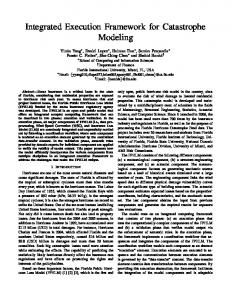
Most commercial modeling systems now adequately support part modeling. These systems are typically feature modeling systems, allowing a user to store functional information on the parts in a model. However, such systems offer only limited facilities to represent assembly information 关3兴. The relations between the components in an assembly usually have to be specified using low-level relations, such as mate and align. In addition, these systems usually provide only a single interpretation of the product for both part and assembly design, whereas part and assembly design focus on different aspects of the product. There are some research systems that adequately support modeling of assembly aspects of a product, but their models are, in turn, less suitable to support part design 关4 – 6兴. The main problem of having separate part and assembly modeling systems is that part-oriented requirements cannot be automatically checked during assembly design, and vice versa. To be able to perform such checks, information has to be exchanged from one system to the other, sometimes by hand, possibly leading to inconsistency of the models in the two systems. A solution to this problem is the approach to integrate part and assembly modeling summarized here. It supplies functionality of both a part modeling system and an assembly modeling system, maintains integrated part and assembly models, and thus solves the problems of data exchange and inconsistency. This approach is based on the multiple-view feature modeling concept, which provides specialized interpretations of a product for different product development phases by means of views. Each view has its own feature model of the product, with features relevant for the corresponding development phase. Here, there are a detail design view and a manufacturing planning view for each part, and an assembly design view for the whole product. All views are kept consistent, i.e. changes in one view are automatically propagated to the other views. The three types of views, and the way these are kept consistent, will be shortly described now. The feature model of a part detail design view consists of instances of form feature classes present in the feature library for part detail design. A form feature class contains a generic feature shape, and possibly several constraints that have to be satisfied for all instances of the class, e.g. for a hole feature that the radius should be within some interval and that its entrance face should remain open. In addition to these feature constraints, there can be model constraints on one or several form feature instances, e.g. that two slots should be at some prescribed distance. To visualize the feature model of a part detail design view, one or more geometry cameras can be used. A geometry camera can use several line visualization and shading techniques, in various combinations 关7兴. It can provide insight into the feature model by visualizing all sorts of engineering information, e.g. highlighting all features of a specific class, or displaying all closure faces of subtractive features or all intersections of features. See Fig. 1共a兲 for a geometry camera window for a part detail design view. To create the feature model of a part detail design view, modeling operations are available to add, remove and change the parameters of a feature or a model constraint. After each operation, the validity of the model is checked on the basis of all feature and model constraints in the model. If the model is no longer valid, i.e. any of these constraints is violated, the user is assisted in making it valid again 关8兴. The feature model of a part manufacturing planning view is similar to that of a part detail design view, but consists of instances of form feature classes present in the feature library for manufacturing planning. Whereas the library for part detail design contains both additive 共material adding兲 and subtractive 共material removing兲 features, the library for manufacturing planning contains only subtractive features. Again geometry cameras can be used to visualize the feature model of a manufacturing planning view; see Fig. 1共b兲 for a geometry camera window for the manufacturing planning view for the same part as shown in Fig. 1共a兲. Although the manufacturing planning view of a part will usually
Fig. 1 Geometry camera windows for detail design view „a… and manufacturing planning view „b… on a part
be derived from the part detail design view, it is also possible to directly modify the feature model of the manufacturing planning view to improve manufacturability of the part. For the latter, the same modeling operations are available as for the part detail design view. The feature model of the assembly design view contains components and connection features between components; a set of components connected by connection features forms an assembly. A component is either a single component or a compound component. A single component represents a part in the assembly design view. A compound component encapsulates an assembly for further assembly modeling operations, by hiding its internal structure of components and connection features, and dealing with the boundary of the assembly only. A connection feature is an instance of a connection feature class present in the feature library for assembly design. A connection feature class contains a description of the types of the form features needed on the components for the connection, several constraints that specify the relations between the components, such as the internal freedom of motion, but also the way the connection can be established 关5兴. A connection feature instance determines the relative position and orientation of the components involved. Examples of connection features are a rib-slot and a pin-hole connection feature. A component model contains the reference geometry of the component, i.e. the boundary of the part or assembly related to that component, and in addition the form features of the connec-
Journal of Computing and Information Science in Engineering
DECEMBER 2002, Vol. 2 Õ 257
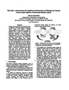
Fig. 2 Windows of a geometry camera for a table model „a…, and a hierarchical graph camera for the table assembly „b…
tion features on the component. So, only the regions of the component that are relevant for assembly are described by form features, whereas the rest of the component is not. To visualize the feature model of the assembly design view, both geometry cameras and graph cameras can be used 关7兴. A geometry camera shows the reference geometry of a component with lines, and the form features of the connection features on the component with shaded faces 共see Fig. 2共a兲兲. Graph cameras show the structure of an assembly. A hierarchical graph camera shows the hierarchy of an assembly with its components and their subcomponents 共see Fig. 2共b兲兲; a relational graph camera shows the connections between the components. To create the feature model of the assembly design view, operations are available to add a connection feature between different components, to change the parameters of a connection feature, to remove a connection feature, to make a compound component out of an assembly, and to turn a compound component back into an assembly. Adding a connection feature between components requires the appropriate form features, e.g. a pin and a hole for a pin-hole connection feature, to exist on the components. If such a form feature does not yet exist in the assembly design view, it has to be created. If the shape for the form feature already exists on the reference geometry of the component, the form feature can be created by feature recognition; otherwise, the form feature has to be created by adding the form feature, including its shape, to the reference geometry. The part detail design views, the part manufacturing planning views and the assembly design view are kept consistent, by automatically propagating changes made in one view to the other views. The detail design view and the manufacturing planning view on a part are kept consistent by feature conversion 关9兴. The part detail design views, and indirectly the corresponding part manufacturing planning views, are kept consistent with the assembly design view by linking the part detail design models to the related single components in the assembly model. When a form feature for a connection feature is added to some component, and this changes the shape of the component, this change is propa258 Õ Vol. 2, DECEMBER 2002
gated to the feature model of the related part in its detail design view by feature conversion again. When a part detail design view is changed, the reference geometry of the related single component in the assembly design view is updated. See Fig. 3 for an example of keeping several views consistent. Integration of detail design and manufacturing planning of parts, and assembly design of the whole product, can be very profitable. It enables requirements on parts to be taken into account during assembly design, by propagating changes made in the assembly design view to the relevant part detail design views, and thus to the corresponding part manufacturing planning views. In a part detail design view and/or a part manufacturing view, requirements on the part can be checked; an example of this is given in Fig. 3. The other way around, it also enables requirements on assemblies to be taken into account during part design, by propagating changes made in the part detail design or the part manufacturing planning view to the assembly design view, where requirements on the assembly can be checked. For the checking, or more in general for the modeling, it is advantageous to provide specialized views on a product for part and assembly modeling, because these focus on those product aspects that are relevant for their type of modeling. See Ref. 关1兴 for more details. The concept of integrated part and assembly modeling can already be very useful to support a single engineer in the development of a complete product, but will become even more valuable when it is made available to a team of engineers involved in the development of a product. This is the subject of the rest of this paper.
3
Collaborative Product Modeling
In this section, we first discuss proposals that have emerged so far in the area of collaborative product development, and then describe the main characteristics of our new collaborative framework. 3.1 State of the art. All three aspects of the working procedure in current development teams mentioned in Sec. 1 are very Transactions of the ASME
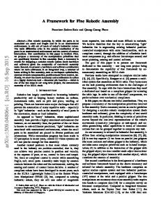
Fig. 3 If a detail design view on a part „a… and the assembly design view on the related component „b… become inconsistent because a form feature for a connection feature is added to the component „c…, then the feature model of the part is updated accordingly „d…. The resulting invalid feature model of the part is made valid again by reducing the height of the passage „e…, thus increasing the distance between the passage and the new form feature, and the reference geometry of the component is updated accordingly „f ….
poorly supported, if at all, by current CAD systems 关10兴. So far, only a small number of tools have been developed that somehow support collaborative design activities. For example, tools for collaborative model annotation and visualization via Internet are now becoming available, providing concepts such as shared cameras and telepointers 关11,12兴. However, such tools are primarily focused on inspection, using simple polygon mesh models, and do not support real modeling activities. In other words, they are valuable assistants for teamwork, but no real CAD systems. Some recent efforts have explored the possibility of enhancing existing CAD systems with collaborative facilities. For example, several commercial CAD systems are now offering functionality for multi-user, token-based asynchronous manipulation of a CAD model 关13,14兴. The heavy requirements for concurrency and synchronization in a collaborative modeling context lead almost inevitably to the adoption of a client-server architecture, in which the server provides the team members not only with the indispensable commu-
nication, coordination and data consistency tools, but also with the necessary modeling facilities. In client-server systems, it is important to balance the complexity of the client application and the network load. In a collaborative modeling context, client complexity is mainly determined by the modeling and interactive facilities implemented at the client, whereas network load is mainly a function of the kind and size of the model data being transferred to/from the clients. Some collaborative modeling prototype systems follow a fat client scheme 关15,16兴. Fat clients are able to manipulate their local copy of the model data. This choice leads to good interactive and visualization facilities, but comes at the cost of a rather heavy network load due to the frequent synchronization of model data among clients. Furthermore, fat clients are typically platform-dependent applications that require more complex installation and maintenance procedures, and are therefore less practical in a multi-platform environment, in particular across various enterprises. Other prototype systems follow a thin client scheme 关10,17,18兴. Thin clients can profit from the use of feature models at the server, where all modeling operations are performed. A limited amount of model data, required at the clients for real-time display, navigation and interaction, is derived at the server and broadcast incrementally to the clients, thus keeping the network load at acceptable levels. To the best of our knowledge, there is currently only one commercial client-server system offering some synchronous collaborative modeling facilities, OneSpace 关19兴, but this system is severely constrained by the model format into which it converts all shared CAD models. For a collaborative modeling system to be successful, it should combine a good level of interactivity with the sort of visualization typically provided by conventional CAD systems. Users will not be able to design adequately if they have to wait a long time after every operation. But increasing interactivity by just porting more and more data and functionality to the clients is not a good solution either, as synchronization problems would then become critical. A web-based client-server approach is more appropriate in such contexts. The prototype system webSPIFF described by Bidarra et al. 关10兴 is a system that follows this approach. It provides collaborative part modeling capabilities to its clients, who can connect to the server to work together using the detail design view and/or the manufacturing planning view on a part. The server has two main components: the SPIFF modeling system and the Session Manager. The SPIFF modeling system provides all feature modeling functionality, including multiple views on a part, and advanced visualization and validity maintenance of feature models. It maintains a central product model, which includes a cellular model for the geometric representation of a part, and canonical shapes representing the individual features in each view. The Session Manager provides functionality to start, join, leave and close a collaborative session, to coordinate the session, and to manage all communication between SPIFF and the clients. In particular, the Session Manager collects all operations requested by the various clients, and schedules them for execution at the SPIFF system. webSPIFF clients perform operations locally as much as possible, e.g. regarding visualization of, and interaction with, their feature model, and only high-level messages, e.g. for specifying modeling operations, as well as a limited amount of model data necessary for updating the client information, are sent over the network. As soon as real feature model computations are required, such as for executing modeling operations, conversion between feature views and feature validity maintenance, they are executed at the webSPIFF server, on the central product model, and their results are eventually exported back to the clients. An important characteristic of this architecture is that by using a central product model, inconsistencies among multiple versions of the model data at different clients are avoided.
Journal of Computing and Information Science in Engineering
DECEMBER 2002, Vol. 2 Õ 259
The next subsection briefly introduces our new collaborative framework for integrated part and assembly modeling, which exploits the webSPIFF facilities just described. 3.2 A New Collaborative Framework for Integrated Product Modeling. The new webSPIFF collaborative framework presented here substantially expands the capabilities referred to in the previous subsection in a number of ways. First, webSPIFF provides a scheme for hierarchically structuring a product into components. In this scheme, each component is assigned to one or more team members, responsible for its actual development. Second, the webSPIFF server can concurrently support several groups of users, each group collaboratively working on its own component of the product. Third, besides providing clients for modeling on part-oriented views, webSPIFF also provides clients with modeling capabilities for assembly design, e.g. to specify assembly relations between components, possibly developed by other team members, by means of connection features. Finally, because at the server the SPIFF modeling system seamlessly integrates in its central product model the part- and assembly-oriented views described in Section 2, propagation of model changes among components can be fully exploited. Before we elaborate in Section 5 how collaborative modeling takes place in this framework, we describe in Section 4 how it supports collaborative structuring of a product into components, and how tasks are assigned to members of the product development team.
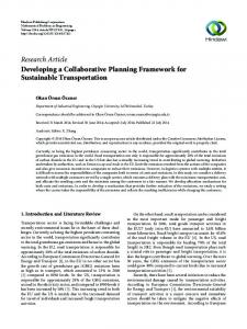
4 Top-Down Product Structuring and Task Assignment To be able to assign tasks to the members of a development team, a product to be developed has to be structured in some way. We use the well-known hierarchical product structure for this. In line with the integrated approach for part and assembly design discussed in Section 2, a product consists of a number of components. Each component can either consist of a number of subcomponents or be a part; the first type of component is called a compound component, the second type a single component. Subcomponents in a compound component are related to each other by means of connection features. See Fig. 4 for a simplified example of a hierarchical product structure. In our approach, product structuring and task assignment go hand in hand. A so-called principal product designer has to start up the hierarchical structuring process for a new product. He can do this by setting up a new product structure, i.e. giving a name to the product, specifying the main components the product consists of, and assigning these components to himself or to other team members 共see Fig. 5共a兲, left兲. This can be easily performed using the Product Navigator, which provides all functionality for building the product structure and visualizing it as it evolves 共see Fig. 5共a兲, right兲. For each component, the team member to whom it was assigned has to specify whether it is a single component 共see Fig. 5共b兲兲 or a compound component. In the latter case, he also has to specify the subcomponents it consists of, and assign each to a team member 共see Fig. 5共c兲兲. The product structuring continues recursively in this way, until all components at the lowest level in the hierarchy are single components 共see Fig. 5共d兲, which corresponds to the product structure of Fig. 4兲. So the product is structured in a top-down way, creating as many levels as desired by the team members, and meanwhile the components are assigned to team members. Notice that product structuring and task assignment are detached from the actual modeling of components. Part modeling of a single component can start as soon as it has been designated as such. Assembly modeling of a compound component can only 260 Õ Vol. 2, DECEMBER 2002
Fig. 4 A simplified hierarchical product structure of a bicycle
start once its subcomponents have been modeled. In both cases, the system signals to the team member共s兲 to whom the component was assigned when modeling can start. Several activities can be done simultaneously in the whole product development process. First, product structuring and task assignment can be done simultaneously for different branches of the product structure. Second, product structuring and task assignment can still be going on in certain branches of the product structure, while in other branches parts or even compound components are already being modeled. Third, modeling of different parts and compound components can also be done simultaneously. So, a product can be developed collaboratively in the sense that several team members can simultaneously work on independent tasks. However, the possibilities for collaboration go much further. In particular, it is possible that several team members are collaboratively working on the development of a same component. The concept of the modeling scope of a team member is important here. It is defined as the set of components he has modeling rights for, and contains the components assigned to him, supplemented with all their subcomponents in the product structure. So for team member E in Fig. 5共d兲, it consists of the set 兵frame, rear fork, left leg, rod, right leg, rear wheel, beam其. This notion of modeling scope is based on the assumption that the development team is also hierarchically structured, and that a team member should have modeling rights for all subcomponents which in the end constitute a component assigned to him, regardless of whether these were assigned to him or to other team members. A team member can also extend the modeling scope of another team member, by granting the latter modeling rights for a component in his own modeling scope. For example, in order to exploit design similarities between the two wheels, team member B could grant modeling rights for the front wheel to team member G 共this is not depicted in Fig. 5共d兲兲. Two or more team members with modeling rights for a component can collaboratively model the component, in the sense that they have simultaneous access to the corresponding feature model and can modify it in a synchronized way. The next section discusses how this actual modeling is done.
5
Bottom-up Part and Assembly Modeling
As mentioned in the previous section, a team member can start modeling a part as soon as it has been assigned to him. On the other hand, modeling of a compound component by a team member to whom it was assigned, can only start as soon as its subcomTransactions of the ASME
Fig. 5 Product structuring and task assignment: new product structure „a…, specification of a single component „b…, specification of a compound component „c…, and final product structure „d…
ponents have been created. So the actual modeling activity is a bottom-up process, starting at the leafs of the hierarchical product structure. If two or more team members have modeling rights for the same part or compound component, they can collaboratively work on it. This is called collaborative part modeling and collaborative assembly modeling, respectively.
5.1 Collaborative Part Modeling. Team members with the appropriate modeling rights can work together on the same part, performing modeling operations available in their view: detail design view and/or manufacturing planning view; see Section 2. Typically each team member will have a geometry camera displaying the feature model of his view. After any of the team members has performed a modeling operation on the part, all the others
Journal of Computing and Information Science in Engineering
DECEMBER 2002, Vol. 2 Õ 261
Fig. 6 Shared cameras of two team members with different views on the same part
will also have the model updated in their cameras. Because all of them have the same modeling rights, several modeling operations on the part may be concurrently specified and sent to the server. Such concurrency is handled at the server, by serializing the operations 关10兴. It may well occur, however, that modeling operations are conflicting, e.g. in the sense that an operation unintentionally cancels the effect of another operation. For this reason, webSPIFF encourages team members to coordinate their actions using some conferencing facility 共phone, chat channel, etc.兲. In addition to this, webSPIFF provides team members with so-called shared cameras. All participants in a shared camera share its viewing parameters on the visualized product geometry, possibly in different views 共see Fig. 6兲. These parameters are permanently synchronized, so that every time one user interactively modifies them, the shared cameras of the other participants are automatically updated. webSPIFF also provides each user of a shared camera with a personalized telepointer 关20兴. The telepointers of all participants are constantly updated in all shared cameras. In this way, e.g. when discussing some model detail, participants in a shared camera can always trace back where each interlocutor is pointing at. When a modeling operation results in an invalid part model at the server, i.e. one or more constraints are no longer satisfied, the Session Manager takes the role of coordinating the validity recovery process. In the example of Fig. 7共a兲, the crown part model becomes invalid as a result of increasing the depth of a pocket, which is in fact turned into a passage feature. Initially, the team member who issued the operation is presented a validity maintenance panel 共see Fig. 7共b兲兲, where useful information on the particular invalid situation is given, together with validity recovery hints 关8兴. This team member can specify corrective modeling ac-
Fig. 7 Collaborative validity maintenance
262 Õ Vol. 2, DECEMBER 2002
Fig. 8 Three components „a… are connected into the front fork assembly of a bicycle „b…, of which the crown part is subsequently adjusted to make room for the front wheel „c…
tions himself and/or hand over the validity maintenance panel to another team member involved, until they agree on the corrective actions and issue their execution. At any moment during a collaborative modeling session, a team member may invite a colleague to join a discussion on a part in his modeling scope, either simply as an advisor, e.g. as participant in a shared camera, or as a participant with full modeling rights. 5.2 Collaborative Assembly Modeling. Collaboration is also possible in the assembly design view, among team members who have appropriate modeling rights on some compound component. As explained in Section 2, modeling operations in the assembly design view consist of creating, modifying or removing connection features, which specify how components should be connected to each other. For example, in the model structure of Fig. 5共d兲, the front fork lies in the modeling scope of team members A and B, and therefore they can together establish the connections between the two legs and the crown of the front fork 共see Fig. 8共a兲 and 共b兲兲. Similarly to what was described in the previous subsection, team members can discuss assembly issues, e.g. where and how to create a connection feature, using shared camera and telepointer facilities. In the assembly design view, these facilities are available for both geometry and graph cameras. An important aspect here is that establishing a connection feature may require the creation of the respective form features on the components involved. As explained in Section 2, because of the integration of all views, these component changes are propagated downwards in the hierarchy to the respective parts, where new form features are also created. It may occur that such a form feature causes the part it is located on to become invalid. In this case, the collaborative validity maintenance scheme mentioned in Subsection 5.1 assists the team members involved in recovering validity again. In addition, if assembly considerations require adjustments in any of the single components, the team members can either switch to that component’s part detail design view and directly adjust it, or invite the team member共s兲 to whom that part has been assigned to join the discussion and perform these adjustments. Because of the integration of all views, changes performed on a part are now propagated upwards in the hierarchy to the compound components which contain the part. So, for example, in the assembly model of Fig. 8共b兲, if team members A and B find that the legs of the front fork are too close to each other, they can decide to extend the crown in its part detail design view, after which they can check whether with this adjustment the crown component satisfies the front fork requirements in assembly design view 共see Fig. 8共c兲兲. Transactions of the ASME
Fig. 9 Top-down specification using the Product Navigator
6
Example Modeling Session
In this section, several steps of an example modeling session with webSPIFF are presented that illustrate the usefulness of the collaborative framework. The scenario consists of designing a height-adjustable office table by a team of four designers. Team member A is the project coordinator, and initiates the session by specifying the table’s main components in the Product Navigator -left and right table legs, tabletop and mechanism-, and assigning these to the other team members: B, C, and D, respectively 共see Fig. 9共a兲兲. After that, these team members take over the task of further specifying their components. Team member B, for example, structures a table leg around three single components: a leg base, a leg top and a tabletop support 共see Fig. 9共b兲兲. At the same time, team member D, who works at a third-party company specialized in mechanisms, specifies the mechanism structure in terms of the following single components: a drive shaft, two transmission boxes, two vertical leg shafts and a crank 共see Fig. 9共c兲兲. Both B and D assign the components to themselves. Because some of these components have to interface with components of other team members, they agree in granting each other modeling rights for those components: team member B assigns the two leg to components to D, and the two tabletop support components to C; and team member D assigns the two transmission boxes to B 共see Fig. 10兲. At some stage, user C, responsible for the tabletop, has finished the actual modeling of his component, according to the dimensions in the specification he received from A. Later on, team members B and D initiate modeling of their components, which can proceed simultaneously. For designing the leg top and the transmission box, they ‘‘come together’’ in a synchronous session on these related parts, and use shared cameras to discuss and agree on their common dimensions 共see Fig. 11兲. While D continues modeling the remaining parts of the mechanism, B switches to assembly view, and assembles the leg base and the leg top components, by specifying the appropriate ‘‘rectangular-pen-hole’’
Fig. 11 Collaboration between users B and D, for matching leg top and transmission box dimensions
connection feature between them 共see Fig. 12兲. Subsequently, he invites team member C to a joint modeling session, in order to make sure that the length of the tabletop support parts matches the corresponding tabletop dimension. Once D has finished specifying the assembly connections among the mechanism components 共see Fig. 13兲, the system signals A that his components are available for the final assembly phase. At this stage, team coordinator A can specify the necessary final connections between: — the transmission boxes and the leg tops; — the vertical shafts and the leg bases; and — the tabletop supports, the transmission boxes and the tabletop. The final assembly model is that shown in Fig. 2共a兲, together with its hierarchical graph, Fig. 2共b兲.
7
Conclusions
A new collaborative framework has been presented that supports integrated design of parts and assemblies. In this framework, collaborative sessions via Internet are made possible, among several members of a product development team. A product can be hierarchically structured, with compound and single components, and meanwhile tasks can be assigned to team members. During the actual modeling, each team member can have his own specific view on the product, in particular a part detail design view, a part manufacturing planning view, or an assembly design view. All these views are kept consistent, by using a central product model. The collaborative framework not only offers facilities to simultaneously work on independent tasks in a product development process, but also synchronous facilities to really collaborate on the
Fig. 10 Final task assignment for the fully specified product
Journal of Computing and Information Science in Engineering
DECEMBER 2002, Vol. 2 Õ 263
products and large development teams. However, we believe that problems arising in this respect may be solved by using a distributed server approach, because independent components of a product can be handled by different servers, running their own modeling system, but coordinated by a single Session Manager. A useful extension would be to incorporate conceptual design and assembly planning views in this collaborative framework. The former would allow a more global specification of components and interfaces, prior to the definition of detailed geometry; the latter would bring in assembly sequencing and other assembly considerations. Together, these would represent another important step towards a collaborative and integrated product modeling system covering the entire product development process.
References
Fig. 12 User B establishes a connection between two table leg parts
design of a same component. These include, among other things, a concurrency handling mechanism, shared cameras with personalized telepointers, and a powerful collaborative validity maintenance scheme. Together with the integration of part and assembly modeling, this means a major step forward in collaborative modeling. The framework capitalizes on the client-server architecture described in Ref. 关10兴. In particular, the functionality provided by each specialized client, both in part design and in assembly design views, guarantees that the computational requirements for the clients, as well as the network load, are kept low. The server, on the other hand, may become rather heavily burdened for complex
Fig. 13 Final mechanism components, designed by user D
264 Õ Vol. 2, DECEMBER 2002
关1兴 Noort, A., Hoek, G. F. M., and Bronsvoort, W. F., 2002, ‘‘Integrating Part and Assembly Modelling,’’ Comput.-Aided Des., 34共12兲, pp. 899–912. 关2兴 Bullinger, H.-J., and Warschat, J., 1996, Concurrent Simultaneous Engineering Systems, Springer-Verlag, Berlin. 关3兴 Deneux, D., 1999, ‘‘Introduction to Assembly Features: an Illustrated Synthesis Methodology,’’ Journal of Intelligent Manufacturing, 10共1兲, pp. 29–39. 关4兴 Heisserman, J., and Mattikalli, R., 1998, ‘‘Representing Relationships in Hierarchical Assemblies,’’ CD-ROM Proceedings of the 1998 ASME Design Engineering Technical Conferences and Computers in Engineering Conference, ASME, New York. 关5兴 van Holland, W., and Bronsvoort, W. F., 2000, ‘‘Assembly Features in Modeling and Planning,’’ Rob. Comput.-Integr. Manufact., 16共4兲, pp. 277–294. 关6兴 Whitney, D. E., and Mantripragada, R., 1998, ‘‘The Datum Flow Chain: A Systematic Approach to Assembly Design and Modeling,’’ CD-ROM Proceedings of the 1998 ASME Design Engineering Technical Conferences and Computers in Engineering Conference, ASME, New York. 关7兴 Bronsvoort, W. F., Bidarra, R., and Noort, A., 2002, ‘‘Feature Model Visualization,’’ Computer Graphics Forum, 21共4兲, pp. 661– 673. 关8兴 Bidarra, R., and Bronsvoort, W. F., 2000, ‘‘Semantic Feature Modelling,’’ Comput.-Aided Des., 32共3兲, pp. 201–225. 关9兴 de Kraker, K. J., Dohmen, M., and Bronsvoort, W. F., 1997, ‘‘Maintaining Multiple Views in Feature Modeling,’’ Proceedings of Solid Modeling ’97Fourth Symposium on Solid Modeling and Applications, Hoffmann, C. M. and Bronsvoort, W. F. 共Eds.兲, ACM Press, New York, pp. 123–130. 关10兴 Bidarra, R., van den Berg, E., and Bronsvoort, W. F., 2002, ‘‘A Collaborative Feature Modeling System,’’ J. Comput. Inf. Sci. Eng. 2共3兲, pp. 192–198. See also: http://www.webSPIFF.org 关11兴 Kaon, 2001, HyperSpace-3DForum. Kaon Interactive Inc., Cambridge, MA. http://www.kaon.com 关12兴 WebEx, 2002, WebEx Meeting Center. WebEx Communications Inc., San Jose, CA. http://www.webex.com 关13兴 Parametric, 2001 Pro/ENGINEER 2001i. Parametric Technologies Corporation, Waltham, MA. http://www.ptc.com 关14兴 SDRC, 2001, I-DEAS. SDRC, Milford, OH. http://www.sdrc.com 关15兴 Nam, T. J., and Wright, D. K., 1998, CollIDE: ‘‘A Shared 3D Workspace for CAD,’’ Proceedings of the 1998 Conference on Network Entities, Leeds. 关16兴 Stork, A., and Jasnoch, U., 1997, ‘‘A Collaborative Engineering Environment,’’ Proceedings of TeamCAD ’97 Workshop on Collaborative Design, Atlanta, GA, pp. 25–33. 关17兴 Lee, J. Y., Kim, H., Han, S. B., and Park, S. B., 1999, ‘‘Network-centric Feature-based Modeling,’’ Proceedings of Pacific Graphics ’99, Kim, M.-S. and Seidel, H.-P. 共Eds.兲, IEEE Computer Society, Los Alamitos, CA, pp. 280– 289. 关18兴 Shyamsundar, N., and Gadh, R., 2001, ‘‘Internet-based Collaborative Product Design with Assembly Features and Virtual Design Spaces,’’ Comput.-Aided Des., 33共9兲, pp. 637– 651. 关19兴 CoCreate, 2002, One Space Suite Solution. CoCreate Software, Inc., Fort Collins, CO. http://www.cocreate.com 关20兴 Valin, V., Francu, A., Trefftz, H., and Marsic, I., 2001, ‘‘Sharing Viewpoints in Collaborative Virtual Environments,’’ CD-ROM Proceedings of the IEEE Hawaii International Conference on System Sciences, Maui, Hawaii.
Transactions of the ASME