Abstract. We present in this work a robust color transformation which ... The two goals of the color image processes are identified as: .... mentation in SciLab.
A color transformation for robust detection of color landmarks in robotic contexts Ramon Moreno, Manuel Graña, Alicia d’Anjou University of the Basque Country, UPV/EHU Grupo de Inteligencia Computacional http://www.ehu.es/ccwintco
Abstract. We present in this work a robust color transformation which has been applied succesfully to natural scenes allowing the fast and precise segmentation of regions corresponding to color landmarks under uncontrolled lightning. The process is grounded in the the Dichromatic Reflexion Model (DRM) and the properties of the RGB space.
1
Introduction
Robust and fast detection of color regions is one of the typical artificial vision problems. Given our color perception, color clustering is not an appropriate approach most of the times. Among the various color spaces, the HSV and CIE L*a*b [1] are the ones closest to human perception. We work on the RGB space, where the DRM model is defined [2]. The need to detect color regions steems from its conventional use in signaling: red for danger, blue and green for informative, yelow for danger advice. Also Red, Green and Blue are the basic colors in the RGB space unit cube. All the remaining colors are represented as linear combinations of these colors. In robotic contexts, working on artificial environments, we must benefit from this information source by the robust detection of signaling symbols drawn in the basic colors. A critical problem is removing the reflections in the image, which interfere with the observed surface. The two goals of the color image processes are identified as: efficient color detection and reflection removal. We present an efficient solution to these problems on the RGB space, using the idea of Specular Free images [6,3]. In the following, section 2 presents a brief explanation of the DRM model and its justification in the RGB space. We present our method in section 3. We present some experimental results in section 4. We give our conclusions and further work lines in section 5.
2
Some properties of the RGB cube and the DRM
Human chromatic perception is the resul of biological evolution along millions of years. The mental interpretation of colors is subject to subjective aspects:
philosophical, cultural and evolution. We can say that the human beings have developed individual color perception traits. However we have a consensus on the basic color interpretation which is represented in the color space used for their representation. The HSV color space is one that matches the human perception better than the RGB space. The pair Hue-Saturation defines the chromatic space, while V is the light intensity. 2.1
Some properties of RGB
The most used color space is RGB. From the computational point of view, and the artficial vision one, the RGB space has the following interesting properties: 1. It is the default color representation space for all the machines, from perception (Bayer’s mosaic) up to the monitor visualization. 2. The vertices of the unit RGB cube represent the primary colors (red, blued, green), the secondary colors (yellow, cyan, magenta) and the black and white colors. The ones most used in signalization. 3. The reflections or brights are characterized in the RGB cube for its proximity to the black-white diagonal. 4. The Dichromatic Reflection Model (DRM) has been defined in the RGB space. 2.2
Dichromatic Reflection Model (DRM)
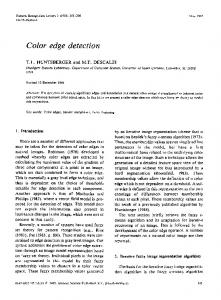
The DRM was introduced by Shafer [2], explaining each point of the observed surface as the sum of two components: a diffuse component D and an specular component S, as can be appreciated in figure 1. The diffuse component refers to the chromatic properties of the observed surface, while the specular component refers to the light color. Reflections in the surface have a great content of the specular component. Algebraically, DRM is expressed as I(x) = md (x)D + ms (x)S where md and ms are weighting values for the diffuse and specular components, respectively, and their values are in the range between 0 and 1. Therefore, a surface with homogeneous chromatic features can be expressed as the sum of two colors, its own and the illumination color. In figure 1 the shadowed region represents the convex region of the plane Πdc containing all the possible colors expressed by the above equation. For an scene with several colors, it will be expressed as I(x) = md (x)D(x) + ms (x)S, where D depends on the spatial localization x. However, still S is independent of the spatial localization x, assuming that the illumination chromaticity is constant for all the scene. Finally, the complete model is expressed as I(x) = md (x)D(x) + ms (x)S(x) where both chromaticities depend on the spatial localization: several surface and illumination colors. 2.3
RGB festures from the DRM point of view
The DRM expresses the color of each pixel as the sum of a difuse and specular components. Mos authors assume a uniform illumination as a problem simplification. This simplification is correct, because most of the times the illumination
Fig. 1. Dichromatic reflection model
color is close to the pure white. However, working in constant illumination chromaticity, we can obtain it used several methods[4,5]. We can classify image pixels into:
– Diffuse pixels: showing the observed surface color, with an almost null specular component. – Specular pixels: whose specular component is much bigger than the diffuse component. Placement of difuse and specular pixels is qualitative different in the RGB cube. Let us focus on the proximity of pixels to the black-white cube diagonal, defined − − as Lw : (r, g, b) = P + s→ u ; ∀s ∈ R where P = [0, 0, 0] and → u = [1, 1, 1]. Given a uniform color region, without any specular component, its representation in the RGB cube would be a line, the diffuse chromaticity line for this region. However, due to noise, it appears as an elongated point cloud. Given a uniform color region, with high specular component, from the DRM point of view, it must appear as a line parallel to line Lw or approaching it. Again, due to noise, an elongated pint cloud appears. Specular image regions have RGB representations far from the color space origin. Finally, a uniform color region (color constancy) with some non negligible specular component must show a V shape. The point cloud beginning in the coordinate origin and go away from line Lw contain the diffuse points, while the ones close to it are the specular ones. Using this knowledge, we can penalize the specular component and magnify the diffuse component.
Algorithm 1 SF2 // I is a image in RGB // IR is the transformed image function IR = SF2(I) New_Intensity = (max(I,3)-min(I,3)); Imghsv = rgb2hsv(I); Imghsv(:,:,3) = New_Intensity; IR = hsv2rgb(Imghsv); endfunction
3
Method
Being interested in pure color regions, we expect their color representation in the RGB cube far from the line Lw . On the other hand, we want to penalize specular regions, those close to line Lw and far from the coordinate system origin. A main feature of line Lw is that the three components of its points are equal r = g = b; ∀r, g, b ∈ [0, 1]. For pixels close to this region, we have r ' g ' b; ∀r, g, b ∈ [0, 1]. As the pixels fall away from this line, the differences among their components are greater. We use this difference as the intensity of the processed image. As we want to preserve the chromatic information, only the intensity is modified, boosting the diffuse pixels and nullifying the specular pixels. The new intensity of the pixels is computed as difference between the maximum and minimum of their RGB components: Intensity = max (I) − min (I) {r,g,b}
{r,g,b}
This intensity replaces the V component in the HSV representation, thus preserving the chromatic content of the pixel. We show in algorithm 1 an implementation in SciLab. 3.1
Application
The SF2 image, the one obtained after the described transformation, is characterized by the absence of reflections, substituted by dark spots. Also the difuse regions are boosted in the image. With an straightforward analysis we can find all the diffuse regions.
4
Experiments
We have performed experiments in thee different contexts: first the detection of markers in real scenes, other with synthetic images, and the last about the detecion of robots in real time. All the results can be viewed in the following web address: http://www.ehu.es/ccwintco/index.php/SMC
4.1
Mark detection
The definition of the experiment is as follows: 1. Context: (a) Place: a lab corridor, with artificial illumination of diverse intensity and uniform color. (b) markers are DIN A4 sheets of different colors: red, cyan, yelow and blue. (c) Standard webcam Phillips SPC 900NC/00 2. Experiment: From each image (recorded in a MPEG file) we find the SF2 images, and there we find the markers. In figure 5 we have thre images from the described scenario. The ones on the left are the closest ones to the camera, the ones on the right are the farthest ones. Notice variations in illumination along the corridor. In figure 3 we show the SF2 images as follows: left corresponding to the middle one in figure 5 , middle after the analysis of the intensity and to the right a zoom of the previous one, showing that one mark is missing. In table1 we show the detections performed on each mark, where ’x’ means good detection and ’+’ incomplete detection..
Fig. 2. Natural images
Fig. 3. SF2 images
Milestone Distance in meters Label 1 Label 2 Label 3 Label 4
4.2
1 23 4 2,6 x x x x
4 x x x x
6 x x x x
5
6
7
8
8.4 10.8 12.8 14.5 17.3 x x x x x x x x + x x x x x x x x x x Table 1. Measures
9
10
11 12 13 14 16
20.7 26.2 31.7 36 41.9 46 50 x x x + x x x
x +
x
x
+
x
Synthetic images
The above color transformation has been applied to natural and synthetic images. Synthetic images have the advantage that we know with precision the color and geometry of the surface, as well as the illumination color. In figure 4 we show some of these images, in the left column we place the original image and on the right the computed SF2 images. First image is a monochromatic image, with a green surface. The second is a Voronoi tesselated surface painted with random colors. Last image is s bichromatic oval. We observe that SF2 images remove completely all the reflections, cancelling the specular component. In the Voronoi tesselated ring surface, besides canceling brights spots, colors have been enhanced. The SF2 method has been ideated for robotic contexts. In figure 5 we show results on three natural images. The two first ones are customary marks in the previously described experiement, and the last one is used by other researchers in the literature of specular correction. The first two scenes show the magnification of the markers in the image. In the last case we see that the bright spots are cleanly removed, respecting original color. 4.3
Real robot detection
The last experiment is the detection of small robots (SR1) in a real scene and real time. The robots are yellow color against a yelowist background, making visual detection tricky. The floor is very bright with many bright spots fromt above illumination. Besides, robot’s upper part contains the printed board and some fixing for the cable being carried. The robots have lots of shadows, thus only a small part of the robot can be clearly detected as pure yellow. Figure 6 contains three images: first the capture from the scene, second its SF2 image, third the SF2 image intensity analysis to detect the robots. The web address http://www.ehu.es/ccwintco/index.php/SMC contains the original video. We must point out that illumination is not constant, there are doors, windows, etc.
5
Conclusions and further work
The work presented here proposes a method for color detection in images, characterized by:
Fig. 4. Synthetic images
Fig. 5. Natural images
Fig. 6. Robots detecction
1. 2. 3. 4.
Being fast and efficient. Removes the specular component. Magnifies color, preserving scene chromaticity, modifying only the intensity. Can work in real time.
Other methos for the removal of the specular component are based on iterative methods that render them unsuitable for real time processing. In the future we will work on the color constancy problem and the color edge detection from the DRM point of view.
References 1. Richard E. Woods Rafael C. Gonzalez. Digital Image Processing. Prentice Hall, 2007. 2. Steven A. Shafer. Using color to separate reflection components. Color Research and Aplications, 10:43–51, april 1984. 3. R.T. Tan and K. Ikeuchi. Separating reflection components of textured surfaces using a single image. In Computer Vision, 2003. Proceedings. Ninth IEEE International Conference on, pages 870–877vol.2, 13-16 Oct. 2003. 4. T.T. Tan, K. Nishino, and K. Ikeuchi. Illumination chromaticity estimation using inverse-intensity chromaticity space. In Computer Vision and Pattern Recognition, 2003. Proceedings. 2003 IEEE Computer Society Conference on, volume 1, pages I–673–I–680vol.1, 18-20 June 2003. 5. Kuk-Jin Yoon, Yoo Jin Chofi, and In-So Kweon. Dichromatic-based color constancy using dichromatic slope and dichromatic line space. In Image Processing, 2005. ICIP 2005. IEEE International Conference on, volume 3, pages III–960–3, 11-14 Sept. 2005. 6. Kuk-Jin Yoon, Yoojin Choi, and In So Kweon. Fast separation of reflection components using a specularity-invariant image representation. In Image Processing, 2006 IEEE International Conference on, pages 973–976, 8-11 Oct. 2006.