A common framewor k for the observation software of astronomical instruments at ESO E.Pozna*a, G.Zinsb, P.Santinc, S.Beardd ESO, European Organisation for Astronomical Research in the Southern Hemisphere,KarlSchwarzschild-Strasse 2, D-85748 Garching bei München,Germany; bLAOG, BP 53, 38041 Grenoble CEDEX 9,France; cI.N.A.F - Istituto Nazionale di Astrofisica, Osservatorio Astronomico di Trieste, Succursale di Basovizza, loc. Basovizza 302, 34012 Trieste, Italy; dUK Astronomy Technology Centre, Royal Observatory, Blackford Hill, Edinburgh EH9 3HJ , UK a
A BST R A C T The Observation Software (OS) is the supervisory software which manages all the exposures and calibrations made by an ESO/VLT instrument. It forms part of the multi-process and multi-layer ESO/VLT instrument software package, receiving astronomer instructions either from a template script or directly from the instrument5s graphical user interface. In order to speed up development, ease maintenance and hence decrease the costs of the Observation Software of different instruments (at various sites 8LT, 8LTI, La Silla, 8ISTA), a software framework BBase Observation Software Stub5 (BOSS) is supplied by ESO. This article introduces the objectives of the tool collecting the general features of all instrument OS, such as configuration and synchronization of the subsystems, state alignment, exposure and image file handling. The basic structure of the implementation is explained (using design patterns), showing the way the framework copes with a challenge of being constantly adjusted to new generic requirements imposed by the complexity of new instruments, performance requirements, increasing image file size and file numbers, and at the same time remaining backward compatible. The instrument-specific features are illustrated via three of many applications: FLAMES is an example of a complex instrument using a “super OS” controlling three instruments as subsystems; AMBER is a VLTI instrument; and VISTA has high performance requirements on image file handling. K eywords: BOSS, observation software, instrument software, control software, exposure control, FLAMES, AMBER, VISTA
1. I N T R O D U C T I O N Astronomical instruments are attached to the foci of telescopes or astronomical interferometer in order to capture the light and transform it into astronomical images or spectra. These instruments are automatically controlled in order to carry out observations as specified by the astronomers. The structure of astronomical instruments varies a great deal. Nevertheless, their hardware components fall into two main categories:
Detector subsystem (D ET) - Various types of detectors may belong to an astronomical instrument: optical detectors (FIERA, TCCD, NGC-OPT [8]); Infrared detectors (IRACE [6], NGC-IR [7][8]) and data recording systems. All these are categorized as detector subsystems (or simply detector s). Instrument subsyste m (INS) - Astronomical instruments are also assembled from numerous hardware devices (e.g. motor devices such as carriage, filter, grating, tip/tilt; mirror; sensor; calibration lamp; etc). A particular group of hardware devices with a particular purpose and/or location are grouped together (controlled centrally) and called an instrument subsystem1. Astronomical instruments may contain several instrument subsystems. *
[email protected] ; Tel: 3200 6441 ; www.eso.org The concept of !"nstrument #$%&'()*+ should not be confused with the concept of !Astronomical Instrument +. The term Astronomical Instrument refers to the global system, which may include several instrument subsystems and several detectors. While Instrument subsystem is a collection of mechanical devices that does not deliver image data, but assist the Astronomical Instrument (e.g. in terms of positioning and/or image quality). For example, the Adaptive Optics system is considered as a special type of Instrument subsystem. 1
The Telescope system (TEL)1 is not a subsystem of the astronomical instrument however it takes an active part in the observation (it is therefore a component of the observation). 1.1 O bservation Software as part of the instrument software
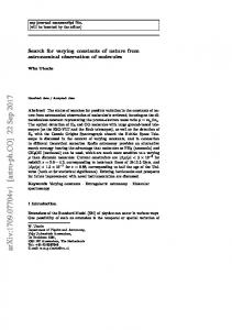
Fig. 1 depicts the observation procedure on a generic astronomical instrument (here showing only one of each type of subsystems2). In order to execute an observation automatically on the hardware, several control software layers have been introduced (see LEVEL-2, 3 and 4). Starting from lowest level, the hardware components (belonging to the categories DET, INS or TEL) are shown inside the column labeled BLEVEL-15. The hardware devices are directly operated via their digital I/O system or motor controllers by control software installed on Local Control Units (LCU-s)3 at LEVEL-2. The LCUs belonging to an instrument or detector subsystem or to the telescope are then controlled by workstation (WS) processes. The workstation control software -represented by circles- may consist of several processes but there is always one main process in charge of the others, which is also responsible for the communication with the outside world.
Fig. 1. Observation procedure on a generic instrument (showing the hierarchy of components and their interaction)
In order to coordinate the various detectors, instrument subsystems and the telescope, the Observation Software (OS) takes over the supervision of the system at the top. The OS gets the parameters and instructions to carry out astronomical observations from the astronomers via observation templates. Templates are coded command sequences. When operators are in charge of the system they typically use G UI s, nevertheless messages can be also sent directly to the OS. The instrument OS may not be the highest control software level though. The astronomical instrument itself may be part of a more complex astronomical instrument, and be controlled by a higher level OS, called the Super Observation Software (SOS). Examples of SOS are instruments FLAMES and SINFONI. The OS is responsible for delivering the images together with information collected from the entire system and then forwarding them to the archive system.
1
The VLT interferometer and the various telescopes at various sites are commonly referred to as Telescope system or telescope. There might be several of both detector and instrument subsystems, or in special cases, there may not be any instance of one or the other type. Note that there is maximum one telescope system belongs to the observation. 3 One LCU can control a group of devices. Typically there are one or two LCUs belong to an instrument subsystem. 2
The communication flow is shown by arrows. The communication between control software takes places via messages, database events and/or files saved on disk s which are marked between the software layers 1 (i.e. on the system boundaries). Note that various high-level control software may reside on the same workstation. Having the processes on the same WS simplifies the communication. From the OS point of view the system under LEVEL-3 is invisible; LEVEL-2 and LEVEL-1 can be considered as black boxes. The OS is only informed about the actions at deeper levels if included in the report of the processes at LEVEL-3. Note that experts can interact with the system at any level. 1.2 Short history of observation software
The idea of standardizing the top level control software of the astronomical instruments at ESO emerged in 1999. Until then the observation software of instruments were individually developed by several consortia, sometimes copying over parts of successful applications. As the number of astronomical instruments was foreseen to increase, the standardization of the control software became inevitable. The hardware devices and detectors have been already consistent, and their associated local control software and workstation control software were established in libraries. What remained was their coordination at the top level. The existing instruments supplied already a lot of experience for establishing the specification for a common observation software, nevertheless the common base needed to be adjustable for specific functionalities. The instrument SW until then were developed using procedural programming, only a then most recent NAOS/CONICA[1,2] consortia approached reusable Object Oriented technologies. After careful analysis the software framework of this instrument was adopted as a base/starting point for BOSS in year 2000. BOSS has since undergone many changes, updates and optimizations to assist ever more complex instruments, a work that is still ongoing. This article introduces the readers to BOSS, starting with the various and growing requirements from its different users, and then focusing on its most significant functionalities: adjustment to the individual astronomical instruments, and the heart of the exposure control procedure as the most relevant functionality of the Observation software. Other relevant areas will be shown on real life applications. Software architecture will be only marginally touched.
2.
O BJ E C T I V ES O F AST R O N O M I C A L I NST R U M E N T C O N T R O L SO F T W A R E
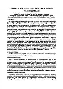
The observation software as a top level command driven control software is responsible for coordinating the actions of the astronomical instrument. Besides its human users: astronomer, operator, and instrument software developer (shown in Fig. 2) it also has system users: the archive system and possibly another instrument. Knowing the features of the astronomical instrument, the astronomer specifies how it should be controlled during observations and calibrations. The requirements differ from case to case, nevertheless they have a common part, which is described below. Common specialties (i.e. that are valid only for a subset of instruments) are illustrated in case of FLAMES (section 4) and VISTA (section 6). Instrument specific requirements are represented by AMBER (section 5). The requirements of the other users are typically common requirements. 2.1 Requirements of Astronomer
The astronomer5s aim is to carry out exposures, for which he needs to prepare the system. Preparation means the S ETUP of all subsystems2 and telescope. The main step of executing exposure s is S TART ing the detector(s) and collecting information from subsystems and the telescope at the beginning and end of exposures. The created image file has to be merged with all information and then to be sent to the archive. The astronomer might need to interact with a running exposure, setting some parameters during the observation, or END or ABORT an exposure. The astronomer instructs the
1
At the boundaries of the different levels the content of local database or disks are scanned/transferred to higher level. Scanning/transferring data is not necessary when the processes occupy the same WS. There is no communication (allowed) between the subsystems of an astronomical instrument and the telescope, (see layers BLEVEL-25 and BLE8EL-35). 2
e.g.: move the instrument devices into given positions; select filter; switch on/off calibration lamps; set integration time of detector;
OS to take care of single or (in case of multiple detectors) simultaneous exposures that might be run consecutively or in parallel via the astronomical templates1.
a)
b)
c)
Fig. 2. Users and their requirements from the Observation Software of astronomical instruments
Around 1999 the exposures on a single detector were run one after the other without any constraint. Nevertheless astronomers soon realised a need for running exposures as efficiently as possible. Initially the aim was to be able to record unforeseen astronomical events. Later it aimed to overcome time loss due to the handling of images2. Furthermore while at the beginning one exposure was associated with one image, later more CCDs became associated with one detector system, producing multiple data files; and also parallel exposures became more frequently used. These requirements have led to a more detailed model/view of the exposures allowing overlapping exposure life cycles belonging to a single detector and resulting in restructured software (see section 3.4 and F ig. 6). 2.2 Requirements of operators
The operator of an instrument relies on a continuous feed back about the global state of the instrument, the executed actions, details of possible errors. During night time he has to put into operation the whole system, during day time or maintenance however he is ought to adjust the software to the partially available system (e.g. telescope should not be moved during daytime or calibration). Important factors of the operation are the state and the status. The term state refers to the OFF, LOADED, STANDBY, ONLINE states, while the term status refers to exposure status (initialised, start phase, running phase, end phase, or idle); The operator monitors the state and status of the global system. Moreover he needs logging and debugging facility and backward-compatible updates in the software. 2.3 Requirements of Instrument SW specialist
The developer of instrument SW needs to be able to develop the system, distinguishing the instrument independent part (BOSS) from the instrument-specific part. He needs a configurable system (see section 3.2) and he needs an easily extendable design, together with a User Manual3 for most commonly occurring software requirements (FAQ). The design is expected also to be adjustable for the implementation of special cases: such as complex systems (combining existing instruments into one global system using SOS (see FLAMES in Section 4); or multiple instruments under one OS; or a system without an image taking detector.
1
The astronomical templates contain a series of commands to be executed by the OS. The results of the exposures are the images. Scientific images have to be saved and sent to the archive while technical images are used for the refinement of observation. 2 3
This was the result of the evolving detectors with higher resolution producing files with increasing size. user manual is available at: ftp://ftp.eso.org/pub/vlt/vlt/pub/releases/FEB2007/vol-5c/VLT-MAN-ESO-17240-2265.pdf
The instrument SW specialist is also responsible for ensuring the performance of the SW; a requirement that is passed on to BOSS (see VISTA in Section 6). 2.4 System users: A rchive system and SOS
The completed images have to be sent to the archive system. The requirement from the archive system is that the file has to be FITS1 standard compliant and its header completed with all necessary information in the form of specified keywords and specified format. One of the latest requirements regards the handling of images with extensions (e.g. World Coordinate System or WCS keywords, and FITS extension sorting). This is explained in more detail on the example of VISTA in section 6. The instrument might be part of a complex system, in which case a higher top level OS communicates with the Instrument OS. This is discussed via FLAMES in Section 4.
3. D ESI G N O F O BSE R V A T I O N SO F T W A R E F R A M E W O R K (B OSS) BOSS is designed to handle instruments with a generic structure shown in F ig. 3 (see O S-i and SuperO S); controlling the standard workstation control processes of INS, D ET, O S subsystems, the telescope and occasionally non-standard control software of so called special subsystems (S PE C ).
Fig. 3 Generic structure of instrument control system at workstation level 3.1 F ramewor k and executable in one package
BOSS primarily serves as a framework, but it also supplies a complete operational OS featuring all aspects of a simple instrument such as the outdated TestCamera. EMMI and SUSI has also started up on the default BOSS but got extended with required changes. To apply the default executable no coding is necessary, specifying the configuration of the subsystems (e.g. name, location and type of process and its database) is sufficient. Corresponding to the various type of requirements the observation software of instruments at ESO contains : o
1
an instrument-independent part which incorporates the common properties of all observation software ( as described in section 2) is a default part of BOSS;
More info on Flexible Image Transport System can be found at http://fits.gsfc.nasa.gov/
o o
an instrument-dependent regular part which is common for a subset of instruments (available as option in BOSS); an instrument-specific part characterizing the specialties of the individual system (occasionally absent, not available in BOSS).
For instruments with specialties the Bdefault OS5 may serve as Bquick debugger5. Comparing the default OS with the instrument specific OS may help identifying the altered behavior and/or detect a source of a reported problem, i.e. whether it belongs to the common software or has been introduced in the overloaded code. 3.2 Declaration of Subsystems
The BOSS package supplies interfaces to the standard subsystems (see Fig. 4.b). The common features of all subsystems are placed in the abstract interface class S UBSYSTEM_BAS E _IF 1. The extended classes then add some specific behavior2. The standard interfaces nevertheless often enhanced by the instrument software developers (Fig. 2) in order to adjust it to the system specific requirements. For special subsystem the instrument software developer has to create an interface based on the closest available built-in interface. a)
b)
Fig. 4 a) BOSS class design showing specification of subsystems using factory method b) available subsystems
BOSS cannot anticipate the information about the subsystems that it must control, therefore the number and type of builtin or user-specified subsystems (i.e. their interfaces) has to be set by the instrument software developer. The specification of such a system where the information may only be known in the subclass, i.e. the subclass is responsible for the creation of objects, is discussed in the literature as the Factory design pattern [7]. BOSS follows the basics of this design pattern3 with some alteration (Fig. 4.a). When user-specified subsystems interfaces are present the class BOSS_SERVER must be sub-classed to generate the needed objects. However when the system is composed from predefined elements only, the subsystem specification is done via configuration only. In this case BOSS_SERVER retrieves the info about the type of the subsystem from the configuration and generates the needed object automatically. 3.3 Basic functionalities
Commands: The users can interact with the OS via commands (e.g. SETUP, START, END). The implementation of all the standard commands are based on the Btemplate design pattern5 [7] as the default realization has to be extendable while keeping the main functionalities of the commands. For this purpose built-in empty functions and functions with simple structure are supplied. Each command is associated with criteria indicating the conditions when it can be executed. Adding new commands is one of the most frequent requirements of Observation Software and it is relatively easy and well supported by various built-in functions checking on subsystem state, exposure status, etc.
1
The abstract class includes: the common part of the interface configuration; empty functions for subsystem-specific actions (following the template design pattern [7]); handling of subsystem state, ignored/available condition; handling of messages and support for synchronization; plus an abstract function to specify how header information is obtained from the subsystem. 2 For example the detector class adds: extended configuration; exposure control command handling (including e.g. the specification of image filename inserting day-of-the-year and serial-number tag); and exposure status handling. 3 The class BOSS_SERVER refers to CREATOR and the abstract S UBSYS TEM_BAS E _I F refers to PRODUCT. Similarly the INS_OS_SERVER refers to CONCREATE_CREATOR and SUBSYSTEM_IF refers to CONCRETE_PRODUCT. BOSS_SERVER then collects all subsystems in a list so that certain actions can be easily run on all of them or a on a subset of them sequentially or parallel (e.g. command setup, see Fig. 6)
Global properties: The monitoring of the state is based on event handling. The global state is the minimum state of all available subsystem, which can be (OFF, LOADED, STANDBY, ONLINE). The handling of global exposure status is based on the similar concept. 3.4 E xposures and optimized exposure sequence
In the beginning, performance of exposures i.e. their operation was not a critical issue. The instruments used to have one image taking detector with one CCD and the exposures were run sequentially using three consecutive commands SETUP, START, WAIT. As part of the exposure life cycle (as shown on F ig. 5) the OS collects information from all available subsystems and the users (e.g. template parameters) during the start and at the end phases of exposures. The information is stored in terms of header keywords and when exposure is finished the image is updated with the header information (this is called merging). With growing image sizes the merging part of the exposures started to expand (e.g. on UVES it took up to 20sec on HP platform). Some instruments (e.g. NAOS) therefore already separated the merging part, directing it to a different process.
SE T UP
Get H DR
ST A R T DET
E N D PH ASE
R U N N I N G PH ASE
ST A R T PH ASE
INTEGRATING
PAUS ED
INTEGRATING
READINGOUT
PROCESSING
TRANSFERRING
Get H DR
M E RG ING
Fig. 5 The life cycle of exposure
Early OS designs had in-built constraints: SETUP was only allowed at the beginning of the exposure; Collection of headers at the beginning had to be finished before the end of the transferring phase; and the image file had to be available when SUCCESS event from detector (to be ready for merging). When merging was carried out by a different process it had to be finished during the running phase of the following exposure and gave no feed back about the merging status to the user. Although these constraints did not affect the operation of individual cases, they were not acceptable for general use for which these constraints cannot be guaranteed. The generalisation imposed additional flexibility from user point of view but more demanding synchronisation mechanism on the OS. This is detailed below:
Optimisation: A detector control software is able to prepare an exposure while another is still running 1. This means that exposure cycles (Fig. 5) may not only overlap when more detectors are in use but may also overlap on the same detector. To exploit this feature BOSS went through major update to make available the optimized exposure command sequence on one detector (see Fig. 6 in the column Btemplate5). The architecture of BOSS design was updated with the following functionalities (see also Fig. 6): o Wait command handling: The optimization has imposed a great impact on the WAIT command (which has a major role in command sequencing). A WAIT command is released at a specified status of a given exposure or exposures. The exposure handling algorithm of BOSS is now prepared to deal with parallel exposures as well as simultaneous WAIT commands (this case is not discussed here). o Track of exposures: In order to handle the possibly overlapping exposures on the same and on different detectors the design had to incorporate a dynamic list of current exposures (Fig. 4.a). For optional debugging a history of passed exposures has been also added as shown on Fig. 4.a. The requirements innate that the mapping between detector and exposure is no longer unambiguous therefore a mechanism for the unique identification of exposures is included. o Synchronization with possible parallel setups: Setup during exposures is necessary for the cases of Bparallel exposures on detectors5 and Boptimization5. Allowing setups while exposures are running naturally imposed another synchronisation point ensuring that actions requested by the OS from the subsystems will not collide. o Different types of detectors: The different detector software have been developed by different groups and therefore they operate slightly differently. They required not only new interfaces ( F ig. 4) but also additional synchronization to make sure the files are ready for processing. Note that multiple images might be produced by one detector. 1
Namely a new exposure can be setup after READING-OUT status is reached and then can be already started while the previous exposure is TRANSFERRING. The upper limit of the frequency of exposures is now approaching the limit set by the detectors integration time (Fig. 5).
o I mage file handling: The final image handling procedure was expected to get more complex and indeed nowadays the images are extended with additional binary tables or multiple images which slows down merging. Although this is fairly automatic adding extra information to the image files is one of the most commonly appearing functionality in the BOSS applications. The merging procedure of BOSS had two seemingly contradictory requirements to comply to. In one case users wish to know the outcome of the whole cycle at the end of each exposure 1. In the other case users wish to run exposures as fast as possible in order not to lose observation time.
Fig. 6 Optimised exposure control on one detector
While preparing for parallel exposures on a multi-detector system, and also for rapid exposures with zero integration time on one detector, it became unavoidable to place the merging action in a separate process and build a queue for it when required ( F ig. 6). In order to report all errors happening during the queued merging, the errors are stored in a local buffer and provided to the user on request. For users who wished to know whether the image has been successfully merged and archived at the end of each exposure, the possibility to synchronise the two processes at the end of each exposures is kept this way (,and backward compatibility is guaranteed in addition). This non-optimized sequence is typically in use in maintenance templates where there is no time constraint. 1
From a performance point of view this is equivalent to having the whole action carried out by one process. Nevertheless having separate process for merging is always beneficial since it avoids the Bhanging5 of main process during the slow merging.
4. A V L T I NST R U M E N T - F L A M ES FLAMES is the multi-object, intermediate and high resolution spectrograph of the VLT, a complex instrument with many special characteristics. One of its most remarkable features from a control software point of view is, that it is assembled from two image-taking astronomic instruments (GIRAF and UVES) and a fiber positioner instrument FP (which supports the simultaneous study of many celestial objects, but does not provide images files). FLAMES, being one of the first instruments using BOSS, has contributed to the improvement of BOSS a great deal. FLAMES controls a standard OS subsystem (GIRAF OS), a non-standard OS subsystem (UVES OS, which predates BOSS) and a nonimage-taking OS (FP OS), i.e. three OS subsystems with three different functionalities.
Fig. 7 FLAMES structure and boundaries
One of the specific features of FLAMES is that it incorporates three instruments, each of which can be controlled as an independent unit and also as part of the assembly. Therefore each instrument has its own OS which at top level can be controlled by the master OS, the so called FLAMES Super OS. The concept of Super OS (also referred to as SOS) has been elaborated during the FLAMES development. SOS includes all the features of a normal OS, and in addition as default the following functionalities has been built in:
Handling of O S subsystem : From SOS point of view the sub-OS has a double role. In one role it acts like an image taking detector, in the other it acts like an instrument subsystem delivering information about the system it controls. Handling of foreign instrument: An SOS is capable of controlling non BOSS–based OS as well (e.g. UVES) provided that an adequate interface is supplied by the instrument software developer. Setup of S O S sub-elements: At top level a scheme using hierarchical identification (e.g. FP.DET) ensures that any element in the structure can be accessed unambiguously. Parallel operation and Exposure handling: SOS allows the handling of independent parallel actions on its subsystems if it is not involved in its exposures. The FLAMES system can be operated in various ways: GR-FP-TEL; UV-FP-TEL; all subsystems together; all subsystem separate. The subsystem that is not running under top level control might be also operated individually via its own template or GUI (see Fig 6.), for example maintenance or calibration of UVES might take place while FLAMES SOS is running exposures on GIRAF coordinating FP and the telescope). Top level control : When SOS is in charge of the system it takes over the handling of merging and control of telescope. The sub-OS automatically detect whether they are under supervision of a SOS . Image file handling: During the handling of the final image file SOS has to make sure that information coming from different subsystems can be distinguished, i.e. coupled to the belonging subsystem. Optimised exposure sequence: FLAMES optimized exposure sequence was achieved by running two templates in parallel.
5. V L T I I NST R U M E N T - A M B E R The VLT Interferometer aims to achieve the spatial resolution equivalent to the one of a 200-m telescope with a sensitivity of an 8-m telescope. AMBER is the near-infrared / red focal instrument of the VLTI (other focal instruments are MIDI and PRIMA). VLTI is composed of several complex subsystems (Unit Telescopes, Auxiliary Telescopes, Delay Lines, Adaptive optics, Infrared Image Sensor) however, they are invisible to OS because the VLTI Control System is in charge of their coordination. The VLTI system acts like a telescope from the OS point of view.
Fig. 8 Structure of AMBER
The size of AMBER OS is amongst the largest BOSS applications (see Table 1) due to its specialties:
F ringe search: The acquisition phase with the interferometric instrument AMBER is more complex than other VLT instruments. The fringes under observation are not always visible therefore a fringe search algorithm is built into the OS based on observables such as object visibility, fringe contrast or piston. Runtime calibration: In order to compensate the atmospheric effect the detector integration time is shorter than few milliseconds. This is achieved on the detector side by extracting the relevant pixel areas only using sub-windows. Nevertheless these sub-windows must be positioned by the OS via continuous runtime calibration. This involves the analysis of the images using a Photometry to Visibility Matrix ( P2VM). This matrix needs to be calibrated every time the spectral configuration of the instrument changes. AD C control: AMBER OS also controls an ADC (Atmospheric Dispersion Compensator). The ADC position is updated before each exposure and set to a position providing an optimal correction at the middle of the exposure.
6. V IST A I NST R U M E N T The VISTA and OmegaCam instruments have so far the highest performance requirements and have therefore contributed to the progress of boss in terms of image handling. These instruments contributed to new functionalities in the base OS: measuring performance; merging of image files into extensions; header handling of extensions (WCS coordinates already appear for CRIRES); and an extension sorting algorithm. The general requirement of sorting the extensions inside the image files came from the archive system. See users on Fig. 4 and section 2.4. Although this might sound to a novice like introducing a huge performance overhead, in practice only the instructions passed on to the merging process had to be sorted, which did not affect the performance at all.
Performance requirement: VISTA is a survey telescope, so it needs the capability to take hundreds of exposures during the night automatically. Furthermore, because VISTA operates in the infrared, those exposures need to be fairly short (between 10 seconds and a minute) to prevent the sky background from dominating. VISTA is designed to work efficiently in the "worst case scenario" of a survey requiring 10 second exposures to be repeated continuously throughout a 14 hour long observing session. Maintaining high efficiency under these circumstances requires the detectors to be read out and the data to be saved to disk as quickly as possible. It also requires that as soon as the detector controller has saved the data to disk it should be free to start the next exposure. This is achieved by allowing the BOSS to complete the data processing and construction of the FITS header for one observation in parallel with the next observation. Optimised exposure sequence: VISTA is also using the optimised exposure (Fig. 6) sequence feature of BOSS. The final timing verification on the instrument workstation at Paranal awaits the VISTA commissioning in summer 2008.VISTA has 16 detectors in the focal plane, which are read out simultaneously by the IRACE [7] detector controller (see F ig. 9). Although the detectors are read out simultaneously, the data acquisition channels are not synchronised (and
cannot be synchronised without compromising the performance), so the order in which the 16 files are created by IRACE is not predictable. This means it is up to the BOSS to merge the files in the correct order.
Fig. 9 VISTA IR Camera OS communication diagram
Image handling: VISTA is a wide-field telescope, so its focal plane has some significant barrel distortion. Another job of the VISTA OS is to maintain a map of where each of the 16 detectors is placed on the sky and write World Coordinates information to the FITS header for each separate IMAGE extension. It uses BOSS functions to add the WCS information to the FITS header of the 16 individual files before they are merged.
7. SU M M A R Y A N D C O N C L USI O NS The generic observation software, BOSS, became a standard part of the VLT software almost immediately after its creation (2000). Since then it has had many applications (Table 1) at various sites. Instances of the VLT in Paranal are e.g. FLAMES, GIRAFFE, SINFONI, SPIFFI, VISIR, CRIRES, HAWKI, while at the VLT Interferometer VINCI, AMBER, MIDI, ARAL are in operation. At La Silla, the observation software for older instruments, EMMI and SUSI, was ported to BOSS; while newer implementations are GRONT and HARPS (which later assisted in the discovery of a new planet). The latest site is currently the new VISTA telescope at Paranal. OS T est C am
Size1 0
Year2
Comment
OS
1998 (port ~2002)
VLT instrument
0 179 150 6219 7432 556 81
2002 2000 2004 2004 2004
VLTI instruments
SUSI EMMI H A RPS GRONT
S ize 106 130 92 113
MIDI VINCI ARAL AMBER SI N F O N I SPI F F I M A CS
VLT instrument; SOS using adaptive optics
F L A M ES GIRA F F E FP
1946 193 511
2002
VLT SOS
C R I R ES
2560
2006
HAWKI
722
2007
Image taking camera
V IST A
3197
2008
Spectrograph, Adaptive optics VISTA instrument
UVES ISF B OSS
14286 11674 25541
1999 1999 2008
(outdated)
Year
Comment
1998 (port ~2001) 1998 (port ~2004)
La Silla Instruments
2003 2007
instrument;
Non BOSS based OS NAOS/CONICA base (main module)– starting point of BOSS Base Observation Software (main module)
Table 1 Size of Observation Software and BOSS
1 2
As calculated by sloccunt showing *.C files only. More info at http://www.dwheeler.com/sloccount/sloccount.html Approximated time of SW delivery
The size of BOSS has more then doubled during the generalization process since it has been founded on the base of NAOS/CONICA[1]. The original base which has incorporated the experience of previous instruments was an adequate starting point though, despite the due re-factoring (i.e. internal architecture change) and extended functionalities such as the exposure handling. A quick look at Table 1 shows that using BOSS ensures that the instrument-specific part of the OS of astronomical instruments has the minimum size, and therefore makes development and the maintenance of all instrument OS software easier. In simple cases (MIDI, TestCamera) no coding is necessary. With the complexity of the instrument the size and complexity of the instrument-specific code increases as well (SINFONI, VISTA, AMBER). This may cover implementation of detailed optical phenomena or involvement of adaptive optics systems or a many-sided SOS. Another benefits of BOSS is that all instruments profit from functional updates. This is not only valid for functional changes but also problem fixing. BOSS not only sits on top of the subsystems but also it is the top user of all software libraries. As such it is sensitive to problems in the whole chain therefore it is thoroughly tested in laboratory. BOSS became a long-run project satisfying many customers. To do so BOSS is not only open for extensions but still open for modifications. Generally, updates on BOSS are only made when a request is proved to be of general purpose (minimum two instruments). One of the latest updates is the support of new generation of detectors [8], while further performance requirements are expected. The challenge of improving BOSS is keeping its design clear, backward compatible and easily extendable. In its currents status it is applicable for users without understanding the details. BOSS has been developed in COO using Bold5 8LT software technologies. In the age of new generation instruments and new generation instrument software the question is should VLT software be replaced and be brought to other platforms. This question is yet to be answered, nevertheless the upcoming instruments P KMOS, XShooter, MUSE and SPHERE P are based on the current ESO standard and hence on BOSS.
R E F E R E N C ES [1]
[2]
[3] [4] [5] [6]
[7] [8]
Zins, G., Lacombe, F., Knudstrup, J., Mouillet, D., Rabaud, D., Charton, J., Marteau, S., Rondeaux, O., Lefort, B., “NAOS Computer Aided Control: an Optimized and Astronomer-Oriented Way of Controlling Large Adaptive Optics Systems”, ADASS, Vol. 216, (2000) Zins, G.; Lacombe, F.; Knudstrup, J.; Mouillet, D.; Rabaud, D.; Marteau, S.; Rousset-Riviere, L.; Rondeaux, O.; Charton, J.; Lefort, B.; Rousset, G.; Hubin, N. N, “QAOS computer-aided control: an optimized and astronomeroriented way of controlling large adaptive optics systems” Proc. SPIE Vol. 4009, p. 395-401 (2000) McPherson, A. M., Born, A. J., Emerson J. P., Jeffers P. F., Little B., Stewart J. M., Egan I., Murray, J., Sutherland W. J, "VISTA: status, performance, and lessons", SPIE, [6267-07] (2006) Dalton G. B., Caldwell M. E., Ward K., Clark P., Strachan M., Sutherland W. J., "The VISTA IR camera", 2006, SPIE conference on "Astronomical Instrumentation", [6269-34] (2006) Santin P., Di Marcantonio, P., Popovic D., Pozna E. , “ESO-VLT Instrumentation the Control Software for the FLAMES-UVES-GIRAFFE observing facility” , Mem S.A.It. 8ol. 73, 23 (2002) Meyer, M., Finger, G., Mehrgan, H., Nicolini, G. and Stegmeier J., "The ESO Infrared Detector High Speed Array Control and Processing Electronic IRACE", Infrared Astronomical Instrumentation, Proceedings SPIE Vol. 3354, p. 134-138, 1998. Gamma, E., [elm R., Johnson R., 8lissides J. “]esign Patterns Elements of Reusable Object Oriented Software” Addison-Wesley 2001 Meyer, M., Baade, D., Balestra, A., Cumani, C., Deiries, S., Geimer, C., Dorn, R., Eschbaumer, S., Finger, G., Mehrgan, L., Moorwood, A., Reiss, R., Reyes, J., Stegmeier J., "NGC Detector Array Controller Based on High Speed Serial Link Technology", Scientific Detectors for Astronomy 2005, Scientific Detectors for Astronomy 2005, pp. 571-578, June 2005.
A C K N O W L E D G E M E N TS Thanks to all who helped specifying requirements: G. Raffi, E. Allaert, R. Schmutzer, A. Longinotti, P. Biereichel, A. Wallender, J. Spyromilio, A. Kaufer, J. Steigmeier and thank you for all the users for their feedback.