pros and cons ofeachintegratortype, because information on them is scam& among many diverse papeas, and is not complete for m e of them. Also, integ" are ...
A Comparative Study of Five Integrator Structures for Monolithic
Continuous-Time Filters -A TutorialT.Georgantas, Y .Papananos, and Y .TsMdis
~ - pgafivc h m s l " ! d~ f0rK fihn me c v a d d thCposaaiOUllSdcsbmt~~~1bssed~sevaal~
I. INTRODUCllON
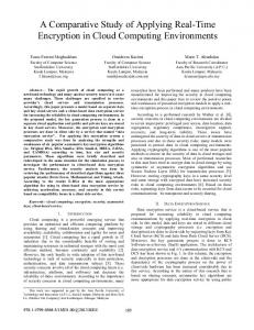
DLlringthepastdecade s e v d new circuits and filtavlgteclmiques for the implmentaton of fdly inteptd cmiinuous time hltas have been repolted (see, [l] and themany papgs.and reftheEin). The main buildmg block of these filters 1s the mtegrator, so if integrator perfarmance is comprehetlsively evaluated, much about ovaall filter perfbfTymecanbepredlcted An mtegrated continuous-time filter designer is fsced with a choice among the various integrator types that have been descrii in the literatme. Unfixhmately, it is very difficult to objectively evaluate the pros and cons ofeachintegratortype, because information on them is scam& among many diverse papeas, and is not complete for m e of them.Also, integ" are o h described in the l i t e " as pert of a larger filter, and the integrator perfurmince can only be judged imlirectly fian the overall filter performance. Finally, the vrpiouS f i b proposed afe &ended for d i f f i applicatians, fi.equency ranges, linearity requirements, dynamic mnge etc.,so it is difficult to compare Meinteg"int. For the above reasons, we have perfmed a detailed cumparison of Werent continuous-time integtatar sttuchnes, and have evaluated each of them m terms of a number of performance cxiteria. The types of integratorswe have considaed,shown in Fig. la-le respectively, are:
+vh'2 Vh/2
Tc
@;I
7 (a) Gm-C INTEGRATOR C
C
4
+"&
+"h/2JL-*+vm
,v
-VJ2
C (b) G m C - O p h p INTEGRATOR
-
+
i) The &-Chkgmkr(e.g. [2]-[SI). ii) The Gm-C-@ampmtqptor(e.g. [6],t7]). iii) The GIIL-OTA mtegratape.g. [8]). iv) The MOSEET-C-Q"p&g"(e.g. [9]-[12]). v) The MOSET-C-OTA hgmbr(e.g. [13]). We note here that we use the tam (Gm) in a d f f m w a y fbnn the tam ampuiet' (OTA), since the latter is basically an op amp witfiwt a low-hpehnce outputstage;it must have ahigh DC voltage gain and opates with an input virtual short circuit, while the is amsided asa voltagecontrolled cu~~ent scurce with well-defined which can accept large input voltages and thus must have a linearized
-
"e
In sechon II, integrator structures are discussed based on several critaia, such as high tkpmcy capability, immto F0Iasitic c a p a c i m active element(s) mplt/ou$ut range requirements, tunability etc. section III contains the canclusions and a brief
discussia 11. INTEGRATOR (%4l"N a) &~I%'lXItAlVR
This is currently the most popular integrator topology [2]-[5], due to the fact that atransconductor does not need a low output mistance stage and can generally be desiped with superior high-fi.equency performancethan its coutlterpartopamp. Active elemmt LX gah mpknmt atxi f@h &qmq#L&. As"g an ideal ,the transfer function is Hi(s) = Vh/Vod = -ao/?., where wo = G , / C . In pactice, however, the-ischaractwsed ' byanon-moutput"e g,andhigh fkquency poles and zeros due tothe parasitic node e f f i in the transconductor stages. These parasitic poles and zeros located, at much higher fiquenaes than the fresuency range of a filter, will be app.oximatedwith a single effective pole correspondrng ' toafi.equency y (for Me sake of simplicity, only the case of a net excess phase will be considered in this and the following sectim).With the previous
assumptions the following transfer firnction results:
%I
C (c) Gm-C-OTA INTEGRATOR
Hni(s)= - (1 + L)(l+ A ) wI 0 2
(1)
where the DC gain is AD, = G,/gout and w1 = w o / A ~= gOut/C
(d)
MOSFET-C-OpAmpINTEGRATOR
(e) MOST-C-OTA INTEGRAIOR
Figure 1
0-7803-1254-6/93$03.00 0 1993 IEEE
is the dopninant pole. " a l l y w,