KSCE Journal of Civil Engineering (0000) 00(0):1-12 Copyright ⓒ2014 Korean Society of Civil Engineers DOI 10.1007/s12205-013-0370-5
Construction Management
pISSN 1226-7988, eISSN 1976-3808 www.springer.com/12205
TECHNICAL NOTE
A Comparative Study of Noise Elimination Algorithms for a 3D Terrain Model through Object Clustering and the Differential Method Hyun-Seok Yoo*, Young-Suk Kim**, and Soon-Wook Kwon*** Received June 24, 2013/Revised March 10, 2014/Accepted April 10, 2014/Published Online October 3, 2014
··································································································································································································································
Abstract The technology to automatically detect the surrounding working environment for modeling of the result is the key essential technique for the automation of the construction equipment developments. When noise takes place during 3D modeling of the front work area of the automated construction equipments, the point of noise occurrence during the surface modeling can result in ground level phenomenon in the form of triangular pyramid to lower the quality of the modeling. This can greatly affect the detection of the objects around the automated equipment. This study proposed revised object clustering and differential algorithms for noise elimination of 3D terrain model and compared the noise elimination performance of existing algorithm and proposed algorithm on the images of actual earthwork working environment. It is expected that the noise elimination algorithm proposed in this study will be very useful as a widely used essential technology required for the development of automated technology not only in earthwork field but also in other general construction and civil engineering fields by noise elimination of the 3D working environment model. Keywords: stereo vision, noise elimination algorithm, 3D terrain model, differential method ··································································································································································································································
1. Introduction The technology to automatically detect the objects around working environment for effective modeling of the result is an essential key technology in developing automated construction equipments because it affects the performance of the developed equipments in terms of the work quality, productivity, etc. The technology for 3D modeling of the local area of the automated construction equipments should be quickly and accurately modeled after the terrain shape of the changing local area in accordance with the work speed of the automated equipment so that its economic feasibility and convenient operation should be assured. Although a stereo camera has been chosen among various working environment modeling equipment to be used for the detection of the interior environment in the robot field, previous research of Yoo et al. (2009) found that the stereo camera, that is applied to earthwork working environment for taking 3D images, manifested better 3D modeling performance in earthwork environment composed of earth soil and rock than in interior environment. However, various noises, i.e., grass, tree root, surface water, concrete hume pipe, manhole, concrete stairs, etc., other than earth soil and rock were captured, and Yoo et al. (2009) suggested an object clustering algorithm to eliminate such noise.
Although the algorithm of Yoo et al. (2009) effectively removed the noise from the images of earth soil, rock, grass, roots, etc., it failed to completely remove the noise from the images of concrete structure or surface water at the side due to the blurring effect of sunlight and resulted in the problem of some loss of ground level. This noise problem not only results in fundamentally lowering of the quality of the 3D modeling and greatly affects the object detection but also can induce the shortcomings of ground level feature being protruded or distorted in the result of the surface modeling through triangle mesh formation. The purpose of this study is to propose an improved noise elimination algorithm for 3D terrain modeling of earthwork environment as an essential key technology for enhancing of the field applicability of an automated excavator by comparing and analyzing it with existing noise elimination algorithm. It is expected that the noise elimination algorithm proposed in this study will be very useful as a widely used essential technology required for the development of automated technology not only in earthwork field but also in other general construction and civil engineering fields by noise elimination of the 3D working environment model. This study aims at developing an improved noise elimination algorithm by using the 3D terrain model, that is obtained from the images of earthwork field taken by a stereo vision camera, and comparing and analyzing the proposed algorithm with
*Research Professor, Dept. of Architectural Engineering, Inha University, Incheon 402-751, Korea (E-mail:
[email protected]) **Member, Professor, Dept. of Architectural Engineering, Inha University, Incheon 402-751, Korea (Corresponding Author, E-mail:
[email protected]) ***Member, Associate Professor, Dept. of Architectural Engineering, Sungkyunkwan University, Seoul 440-746, Korea (E-mail:
[email protected]) −1−
Hyun-Seok Yoo, Young-Suk Kim, and Soon-Wook Kwon
existing object clustering algorithm for noise reduction. The research method is explained in the following. 1. 3D Terrain Modeling and Analysis of the Importance of the Noise Elimination Algorithm First, the importance of 3D terrain modeling in the operation of automated construction equipment and the necessity of noise elimination algorithm in 3D terrain modeling are analyzed. 2. Literature Review of Noise Elimination Algorithm for 3D Terrain Model and Problem Identification The research trend on noise elimination algorithm of 3D terrain model and the problems of existing noise elimination algorithms are analyzed to identify the factors of improvement on the noise elimination algorithm. 3. Proposal of Noise Elimination Algorithm for 3D Terrain Model A revised object clustering noise elimination algorithm, that improves on the judgment of object continuous distance, is
proposed based on the analysis result of the problems of existing object clustering noise elimination algorithm, and the other noise elimination algorithm, that uses differential method to delineate the object boundary from 2D plane data, is also proposed. 4. The optimum noise elimination algorithm for each working environment is proposed based on the comparison analysis of the proposed noise elimination algorithm with the existing noise elimination algorithm in terms of performance speed, quality of noise reduction, and quality of 3D surface modeling for the sample video images of actual earthwork field.
2. Previous Research Literature on Noise Elimination Algorithms 2.1 Importance of Noise Elimination Algorithms and 3D Terrain Modeling In developing automation equipment for construction, the
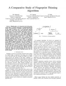
Fig. 1. Form of Noise in 3D Images of Earthworks: (a-1) Soil and Rock (Original Stereo Image), (a-2) Soil and Rock (3D image), (b-1) Concrete Hume Pipe (Original Stereo Image), (b-2) Concrete Hume Pipe (3D image), (c-1) Surface Water (Original Stereo Image), (c2) Surface Water (3D Image), (d-1) Concrete Stairs (Original Stereo Image), (d-2) Concrete Stairs (3D Image) −2−
KSCE Journal of Civil Engineering
A Comparative Study of Noise Elimination Algorithms for a 3D Terrain Model through Object Clustering and the Differential Method
Fig. 2. Form of a Protruding Triangular Prism of the Noise: (a) Original Stereo Image, (b) Noise of 3D Image, (c) Surface Modeling Results
technology needed to recognize the presence of terrain as well as the objects in the work areas is vital for establishing a work path plan on the use of automation equipment. The same threedimensional virtual environment needs to be constructed with the actual work environment so the work environment can be updated in real time. A range of environmental sensors, such as stereo-vision cameras, structured light cameras, 2D laser scanners and 3D laser scanner, have been used to create the threedimension model of the construction automation equipment for the surrounding work areas. The speed, accuracy, affordability and convenience of three-dimensional modeling sensors will help establish the work path and action plans for automation equipment. As an image processing technique through the lens of a camera, the stereo-vision system used in this study can acquire images in real time, obtain color information and threedimensional coordinate information, and shows superior economic efficiency. On the other hand, stereo-vision systems generate more noise in the three-dimensional modeling of the terrain than laser-based sensor systems. In particular, a range of objects, such as soil, rocks, surface water, open-air hume pipes and concrete structures, exist in the earthwork site, which is a target of this study. If the earthwork site is modeled in three dimensions using a stereo-vision system, a relatively small amount of noise is generated in the soil and rocks, but a large amount of noise is generated in surface water, hume pipes and concrete structures, as shown in Fig. 1(a-2). In three-dimensional modeling of the anterior area of the automation equipment for construction, this noise can cause a projection in the terrain shape, as shown in Fig. 2(c), through the creation of a triangle mesh in the 3D terrain model of the point cloud data. This can lead to the degradation of three-dimensional modeling, whereas the automation equipment will affect the recognition of the objects on the terrain significantly. Accordingly, the noise should be eliminated completely before processing the terrain surface modeling. 2.2 Previous Research on Noise Elimination Algorithms In general, 3D data reconstructed from computer vision includes inherent noises. Such noises can enormously influence on the quality of 3D mesh data representing the original object shape after the triangulation process. Therefore, it is very important to effectively eliminate the noises while preserving the geometric features of the original object shape. In the previous researches, Vol. 00, No. 0 / 000 0000
Field (1988), Yagou et al. (2002), Taubin (1995), Kobbelt et al. (1998), Desbrun et al. (1999), Mashiko et al. (2004), Jie and Fuyan (2005) used the differential geometric approach as a preprocessing method for removing such noises. But the differential geometric approach was not effective in an aspect of greatly deforming its geometric features instead of removing the noises on the original object image. Ohtake et al. (2001) and Tasdizen et al. (2002) also implemented studies of removing noises by using normal vector of 3D mesh. However, those filters could not effectively eliminate peak noises which are included in the 3D data reconstructed form the original image. Hyeon et al. (2009) obtained sophisticated 3-dimensional data by eliminating the noise in three-dimensional modeling of 3D cameras according to the area characteristics of the mesh data. In their study, the noise was divided into gauss noise and peak noise according to the area characteristics of the 3D mesh. The noise was eliminated using the intermediate value filter applied on the area ratio and the weighted value of the two-dimensional area and volume. Lee et al. (2009) used the V-depth map to detect obstacles through a road feature extraction. In his study, they relied on the characteristics of the depth that shifted into the vertical direction when the horizontal axis of the camera was parallel to the road surface, and utilized a four-component based labeling algorithm and morphological operations to eliminate noise. Kim et al. (2009) extracted the artificial structures from three-dimensional point cloud data acquired using terrestrial LIDAR. In his study, he eliminated noise by acquiring data on the targeted structures within the threshold by estimating the linear equation of the structures in three-dimensional space. Whitehorn et al. (2003) examined an underground mining site in three dimensions using an LHD (Load-Haul-Dump) device equipped with stereo-vision equipment and lighting. In their research, a ZSSD (Zero-mean Sum of Squared Differences) algorithm was used in the stereo matching process with Gaussian and median filters applied to reduce noise. Yoo et al. (2009) performed threedimensional modeling of the earthwork environment using stereo-vision and eliminated noise by applying a threshold to its size after conducting a clustering process on the noise and terrain objects. 2.3 Review of the Problems of Previous Studies on Noise Elimination Algorithms Lee et al. (2009) examined a straight road as a research target
−3−
Hyun-Seok Yoo, Young-Suk Kim, and Soon-Wook Kwon
but did not verify the reliability of the algorithms under a range of road conditions, such as curved or inclined roads. In addition, it would be difficult to apply this method to an earthwork site, which has a very irregular terrain shape. In the study by Kim et al. (2009), prior data on the color information of the targeted structures was required, and there was a difference in the noise occurrence patterns between the 3D terrain model obtained from the precise terrestrial LIDAR equipment and from a stereovision camera. Hyeon et al. (2009) eliminated noise using the area ratio of two-dimensional data and three-dimensional data in creating a triangle mesh. On the other hand, the noise was divided into only two patterns, such as gauss noise and peak noise, and the triangle mesh modeling conversion time was also required considering the earthwork site, which makes the application problematic. Whitehorn et al. (2003) used preprocessors, such as a Gaussian filter and median filter, to reduce noise in the 3D stereo matching phase. This was effective in reducing the overall image noise level but there were some limitations in treating noise. Yoo et al. (2009) applied a continuity judging distance of 15 cm when calculating the continuity index for object clustering. This poses a problem in a terrain with great curvature because the ground plane is divided into distinct areas, and not modeled as a continuous object. Hence, noise, in the form of stairs, could not be eliminated completely.
3.1 Modified Object Clustering Noise Elimination Algorithms Three-dimensional data from a stereo-vision camera was generated based on two stereo images on both sides using a twodimensional array structure ([i][j] arrangement) with elements including location and color information. Although each pixel of a typical two-dimensional image contains color information (R, G, B), the three-dimensional data from stereo-vision cameras include both color and location information (X, Y, Z) in threedimensional coordinates, as shown in Fig. 3. In the 3D data structure, if the color information is represented in a twodimensional array, two-dimensional stereo matching images are formed, and each point is deployed in three-dimensional space
using the color and location information of each pixel to create a three-dimensional model. The method for eliminating noise from images can be divided into an erosion-based and object recognition-based noise reduction techniques. The erosion-based noise reduction technique gradually erodes points that are applicable to arbitrary conditions until they correspond to the noise, whereas the object recognition-based noise reduction technique deletes the noise intelligently, according to the morphological characteristics of each object after clustering points are adjacent to each other. Generally, the erosion-based noise reduction technique has a disadvantage, where significant data is lost, including the points applicable to noise as well as the points corresponding to the terrain. On the other hand, the object recognition-based noise reduction technique can eliminate noise without losing terrain objects because of its algorithms. Among object recognition-based noise elimination algorithms, the labeling algorithm is used most widely to extract and recognize objects from image data, and as an algorithm for clustering consecutive points into each area. This algorithm can extract objects from plane images by attaching the same label to all connected points. On the other hand, because the labeling algorithm was developed originally for two-dimensional binary images, the continuity criteria in determining the continuance of points that are adjacent to each other and the implementation of new data structures are required in three-dimensional images. In twodimensional binary images, it is possible to extract objects without a separate process because each point is separated by black and white, and the points adjacent to each other in an array of data are the points actually adjacent to each other. In three-dimensional images, however, because each point exists in the X-Y-Z space, the adjacent points in a data array may not be the points adjacent to each other, and it is necessary to determine the continuity using information on the distance between pixels. In connection with this assertion, Yoo et al. (2009) proposed an index structure to determine the continuity between pixels, as shown in Fig. 4. Figure 4 presents a method to determine the continuity of each pixel in a three-dimensional stereo matching image that uses an index structure. First, the distance between the points of the central pixel and the points adjacent to each other is calculated by generating a 3×3 mask through 8 points (d1~d8) adjacent to each other in a data array of the center pixel ([i][j]). If the
Fig. 3. 3D Data Structure of Stereo-Vision Images
Fig. 4. Index Structure in Determining the Continuity between Pixels
3. Noise Elimination Algorithms in a 3D Terrain Model
−4−
KSCE Journal of Civil Engineering
A Comparative Study of Noise Elimination Algorithms for a 3D Terrain Model through Object Clustering and the Differential Method
distance between the points is smaller than a predetermined standard (15 cm), it is represented as a continuous point(true), otherwise, it is represented as a non-contiguous point for calculation. This process is repeated, targeting all points of the three-dimensional images to obtain a continuity index for the entire image. The existing labeling algorithms must be modified to extract objects because the continuity index has a similar data structure to a two-dimensional binary image. In the object recognition-based noise elimination algorithms developed by Yoo et al. (2009), a continuity judging distance of 15 cm was applied in a batch as the continuity judging distance between pixels. On the other hand, because the mean distance between the pixels of a point three meters ahead was just 3.2 cm, but that of a point 40 meters ahead was more than 78.6 cm, the terrain surface was split into multiple objects, and some of the terrain surface was lost when the distance criterion was applied in a batch (Fig. 5). The loss in the terrain surface is caused by the fact that in a case where significant bending curvature of the ground occurs from a point 12 meters ahead, the actual terrain is continuous but the objects are separated, and not modeled as continuous objects because the distance between points exceeds 15 cm. To avoid this phenomenon, it is essential to establish the continuity judging criteria (S[i]) that can be changed dynamically according to the position of the target points and the installation
Fig. 7. Distance between the Original Point and Other Points
angle of stereo-vision cameras. As shown in Fig. 6(a), the three-dimensional data from stereovision cameras form a fan-shaped two-dimensional array [i][j] that is shaped in the form of the terrain in a three-dimensional space. As shown in Fig. 7, if the image is from the stereo-vision camera, which is tilted by δ° in the ground direction, the installation height of the stereo-vision camera is H, the vertical viewing angle, Av, of the stereo-angle is 52.5°, the targeted terrain is assumed to be a complete plane, and the distance, D[i][j], between the original point, O, and a random point, P[i][j], can be expressed by the following Eq. (1): H D[i ][j] = --------------------------------------------------------A A cos⎛ 90 – ⎛ δ – -----v⎞ – -----v ⋅ i⎞ ⎝ ⎝ 2 ⎠ Rv ⎠
(1)
where, Av = Vertical viewing angle of stereo-vision (52.5°) D[i][j] = Distance between O and a random point, P[i][j] (mm) H = Installation height of stereo-vision (mm) Rv = Vertical resolution of stereo-vision (pixel) δ = Z-axis angle of stereo-vision (o) Under the assumption of a plane, the continuity criteria S[i] on random points (P[i][j and P[i][j-1]) is a side of an isosceles triangle, as shown in Fig. 6(b), which was deduced in accordance with the second law of cosines (Eq. (2)), as shown in Fig. 8.
Fig. 5. Loss of the Terrain Surface in an Anterior Region
A 2 2 S[i] = D[i] [j] + D[i] [j – 1] – 2 ⋅ D[i] [j] ⋅ D[i] [j – 1] ⋅ cos ⎛ -----h⎞ ⎝ R h⎠
(2)
where, Ah = D[i][j] = Rh = S[i] =
Fig. 6. Interval between Points of Object Continuity Judging Algorithms: (a) Data Array Structure between Points, (b) Judging Criteria Vol. 00, No. 0 / 000 0000
Horizontal viewing angle of stereo-vision (72.0°) Distance between O and random point P[i][j] (mm) Horizontal resolution of stereo-vision (pixel) Continuity judging distance (mm)
The continuity judging distance calculated by Eq. (2) is used to determine the continuity of 8 neighborhood pixels in the process of the suggested noise elimination algorithms in this study, as shown in Fig. 9. As mentioned above, the noise elimination algorithms suggested in this study underwent a similar process to the labeling algorithm used in existing two-dimensional images, and were designed to perform labeling after determining the continuity of 8 neighborhood pixels so they could be applied to
−5−
Hyun-Seok Yoo, Young-Suk Kim, and Soon-Wook Kwon
Fig. 8. Continuity Judging Distance according to the Vertical Index Number(i) Fig. 10. Object Detection of 2D Data using the Differential Method (Jeong et al., 2008): (a) 2D Scan Line on the Object, (b) 2D Scan Data Cross-Section, (c) 2D Data on the Polar Coordinates, (d) Detection of Differential Graph Features
A differential method is used widely to determine the singularity of object boundary planes in two-dimensional data using a laser scanner. An algorithm used to detect objects in 2-dimensional data involves a process of detecting the singularity of the object boundary planes. The differential method is robust toward changes in the external environment and in the ease of detection by distance. Object detection through the differential method is designed to detect the changes in the pattern of distance values by differentiating the output distance values from a scanner with respect to the scanner interval θ. The basic principle is that the presence of an object is determined by detecting the changes in distance because the distance decreases from d1 to d2 in the boundary planes of objects when the objects exist on the scan lines, as shown in Fig. 10(a) and(b). Accordingly, the derivative (Difference (P[i][j])) on the arbitrary point (Pi) in two-dimensional data is defined, as shown in Eq. (3). Jeong et al. (2008) detected the start and end points of the object corresponding to the peak points in the differential graph (Fig. 10(d)), which differentiates the scan data of 2D, as shown in Fig. 10(b), and recognizes the internal space of an object. D [ i ] [j ] – D [i ] [ j – 1 ] Differential ( P[i ][j] ) = -------------------------------S ( ∆θ[i] )
Fig. 9. Noise Elimination Algorithm Process by Object Continuity Judging
three-dimensional images.
(3)
where, Differential(P[i][j])= Derivative of point P[i][j] (mm/°) D[i][j]= Distance from the original point, O, and point P[i][j] (mm) S ( ∆θ[i] ) = Baseline distance between D[i][j] and D[i][j-1] (mm) ∆θ[i] =Angle between the original point, O and D[i][j], D[i][j-1] (°)
3.2 Noise Elimination Algorithms using the Differential Method −6−
The differential method was originally developed to detect KSCE Journal of Civil Engineering
A Comparative Study of Noise Elimination Algorithms for a 3D Terrain Model through Object Clustering and the Differential Method
Rv = Vertical resolution of stereo-vision (pixel) δ = Z-axis pitch angle of stereo-vision (°) Because the triangle is an isosceles triangle, as shown in Fig. 11(b), assuming that the horizontal viewing angle (70°) of stereovision camera is Ah, the distance S(∆θ[i]) was calculated from the second law of cosines, as expressed in Eq. (5): A 2 2 S( ∆θ [i ] ) = D[i] [j] + D[i] [j – 1] – 2 ⋅ D[i] [j] ⋅ D[i] [j – 1] ⋅ cos ⎛ -----h⎞ ⎝ Rh⎠ Fig. 11. Detection of the Noise Interval: (a) Data Array Structure, (b) Judging Criteria for Continuity between Points
protruding objects in two-dimensional data using a 2D laser scanner but was applied in three-dimensional terrain data using the existing 2D-based differential methods in this study because noise also appears in the form of a protrusion in an irregular terrain in stereo-vision-based three-dimensional modeling. Unlike the singularity detection methods using the differential method in existing two-dimensional models, the noise elimination algorithms of this study, which targets the 3D planar data ([i][j] array), regard the data of each [i] row as two-dimensional data and detect the start and end points of objects repeatedly toward the data of [i]. In this case, the difference in the differential method of existing 2D planar data lies in the distance (S[i]) applicable to the horizontal point-to-point angle (delta θ) that is applied to the horizontal point-to-point distance (D[i][i]-D[i][j-1]) in each row [i] to obtain differential results within the same range in the entire three-dimensional plane. With respect to random points (P[i][j] and P[i][j-1]) on a threedimensional plane, Fig. 11 shows the distance S[i] corresponding to the horizontal point-to-point angle (∆θ). As shown in Fig. 12, assuming that the tilt angle of the stereo-vision camera is d, with a vertical viewing angle (52.5°), Av, and an installation height of the camera, H, the distance D[i][j] between the random point, P, and the original point can be expressed in Eq. (4): A A D[i] [j] = H ⋅ tan ⎛ 90 – ⎛ δ + -----v –-----v ⋅ i⎞ ⎞ ⎝ ⎝ 2 R2 ⎠ ⎠
(5)
where, S(∆θ[i]) = Baseline distance between point P[i][j] and P[i][j-1] (mm) Accordingly, the final differential (P[i][j]) on a random point, P[i][j], in three-dimensional models by Eqs. (3) is shown in Eq. (6): D [ i ][ j ] – D [ i] [ j – 1] Differential( P[ i][j]) = -----------------------------------------------------------------------------------------------------A 2 2 D[i][j] + D[i][ j – 1] – 2 ⋅ D[ i][j] ⋅ D[i][j – 1] ⋅ cos⎛ -----h⎞ ⎝ Rh⎠
(6) Figure 13 shows a cross-section of the plane, in which noise occurs after the differential equation was applied to all points of the three-dimensional models. Because the differential method was originally designed to detect the boundaries of objects, the intervals that exceed the absolute value of the threshold were detected through the application of an arbitrary threshold (within 10 to 20). On the other hand, in the case of a stereo-vision camera whose detection target is noise, there is a problem in the pattern of the differential values that exceed the threshold, which is not uniform, as shown in Fig. 13. To overcome this problem, this study employed a method to detect an interval as the terrain, in which the points not exceeding the threshold are constantly present with a more
(4)
where, Av = Vertical viewing angle of stereo-vision (52.5°) H = Installation height of a stereo-vision camera (mm) Fig. 13. Differential Graph of the Noise Occurrence in Existing Differential Methods
Fig. 12. Distance toward the Viewing Angle of the Stereo-Vision Vol. 00, No. 0 / 000 0000
Fig. 14. Differential Graph of Noise Occurrence in a Continuous Interval Detection Method −7−
Hyun-Seok Yoo, Young-Suk Kim, and Soon-Wook Kwon
than a uniform width (12 points), and eliminated the rest as noise (Fig. 14).
4. Analysis of the Performance of Noise Elimination Algorithms 4.1 Software Implementation of the Noise Elimination Algorithms The stereo-vision camera in this study was installed at the top of the driver’s seat inside the intelligent excavation system toward the bottom of the anterior ground, as shown in Fig. 15, and the threedimensional terrain modeling software of the stereo-vision camera was used in the data processing module that was installed on top of the shelf behind the cockpit of the intelligent excavation system. Intelligent excavation system is designed to process one stereo image which is captured at the moment of receiving trigger signal from the remote control station instead of processing whole dynamic video stream. The processing result (*.loc file) is then resent to the remote control station through a wireless transmission. Once the intelligent excavation system receives the trigger signal, it is supposed to stop running and capture the terrain image. At high illumination work environment, the camera runs with fast shutter speed so that the quality of the captured image is relatively free from the bad influence by the possible equipment vibration. On the contrary, the quality of the captured image can be degraded by the blur effect under low illumination work environment. In order to minimize these possible problems, the lighting system of the intelligent system can be effectively used when the shutter speed goes below 1/100 sec. The stereo-vision 3D terrain modeling software, which included the noise elimination algorithms in this study, was developed as Windows 32-based application software using Microsoft Visual C++ 6.0, and OpenGL (Open Graphics Library) was used for
Fig. 15. Intelligent Excavation System and Stereo-Vision System Hardware Table 1. Three-Dimensional Modeling S/W Operating Environment CPU Mainboard Memory VGA OS
Intel Core i5 Lynnfield 760 @ 2.8GHz ESTAR EXP55 2 × DDR3 2G PC3-10700 Radeon HD5450 HM D2 Windows XP SP3
Fig. 16. 3D Terrain Modeling Software User Interface
software development. Table 1 lists the S/W operation environment used in this study. Because the 3D terrain modeling software developed in this study is in the completely automated excavation mode of the intelligent excavation system, it is operated automatically without an operator, and is designed to display the three-dimensional modeling results on the screen of a remote station, as in the user interface shown in Fig. 16. 4.2 Analysis of the Performance of the Noise Elimination Algorithms In this study, six images, where noise was relatively easy to identify, as shown in Fig. 17, among a total of 108 images acquired from the actual earthwork site were selected as the image samples to analyze the performance of the noise elimination algorithms. The sample images selected were composed of three images featuring soil and rocks, one image featuring surface water, one image featuring concrete hume pipes, and one image featuring stairs. In the image samples of the soil and rocks, there was relatively little noise but there was excessive noise in the other images of artificial structures, such as surface water, hume pipes and stairs. A comparative study was conducted on the performance related to the difference from the original in the case of three-dimensional surface modeling, where the noise elimination quality and processing speed of the suggested noise elimination algorithms were examined, targeting the sample images in Chapter 6. 4.2.1 Measurement of the Processing Speed of the Suggested Noise Elimination Algorithms In this study, the GetTickCount( ) function, which is supported by Microsoft Visual C++ 6.0, was used to measure the speed of the suggested noise elimination algorithms. The function that measures the time in milliseconds (ms) measured only the processing speed of the noise elimination algorithms, excluding the file storage and data-loading time. Based on the results of the test data processing speed of the algorithms, which targeted six images, the mean processing speed of the existing object clustering noise elimination algorithms and
−8−
KSCE Journal of Civil Engineering
A Comparative Study of Noise Elimination Algorithms for a 3D Terrain Model through Object Clustering and the Differential Method
Fig. 18(a-1)~(c-4), the existing algorithms and suggested algorithms succeeded in eliminating the noise completely, but there was some loss in the ground plane of both algorithms. Compared to the original images, the level of the loss in the ground plane was lowest from the modified object clustering, whereas the greatest loss in the ground plane came from the noise elimination algorithms using the differential method. In the case of the images of concrete hume pipes, surface water and concrete stairs, which showed cascaded noise due to the transient light sensitivity, as shown in Fig. 18(d-2), (e-2) and (f2), the existing object clustering algorithms barely eliminated the cascaded noise but the modified object clustering algorithms eliminated more than 90% of the cascaded noise, as shown in Fig. 18(d-3), (e-3) and (f-3). The noise elimination algorithms using the differential method succeeded in eliminating the cascaded noise by more than 98%, as shown in Fig. 18(d-4), (e-4) and (f-4), but also registered the greatest loss in the ground plane. Overall, the modified clustering algorithms eliminated noise effectively, and the level of ground plane data loss was lowest in the images containing soil and rocks. Moreover, the noise elimination algorithms using the differential method eliminated cascaded noise most effectively in the images of hume pipes, surface water, and stairs, where irradiation occurred. Fig. 17. Three-Dimensional Model Samples of the Earthwork Site Images: (a) Earth and Sand 1, (b) Earth and Sand 2, (c) Earth and Sand 3, (d) Concrete Stairs, (e) Surface Water, (f) Concrete Hume Pipes
Table 2. Data Processing Speed of Noise Elimination Algorithms [Unit: ms] Image 1 2 3 4 5 6 Average
Object clustering 375 407 281 266 391 360 346.6
Modified object clustering 375 406 297 265 406 375 354.0
Differential method 109 109 78 94 110 109 101.5
modified object clustering algorithms was 346.6 ms and 354.0 ms, respectively, showing little difference in the processing speed of the two algorithms. On the other hand, the mean processing speed of the noise elimination algorithms using the differential method was 101.5 ms, which is the fastest data processing speed (Table 2). 4.2.2 Analysis of the Quality of the Suggested Noise Elimination Algorithms Comparative analysis was conducted on the noise elimination results between the existing noise elimination algorithms and suggested algorithms, targeting six image samples, as shown in Fig. 18. In the images that included soil and rocks, as shown in Vol. 00, No. 0 / 000 0000
4.2.3 Analysis of the Three-Dimensional Surface Modeling Results of the Suggested Noise Elimination Algorithms In the three-dimensional terrain modeling using stereo-vision, the ultimate purpose of eliminating noise is to minimize the distortion in the terrain surface shape due to noise in the conversion of three-dimensional point cloud data to a surface model. In this study, the performance of each noise elimination algorithm was analyzed, targeting three images of concrete hume pipes, surface water and concrete stairs, which recorded severe noise among the six images after conversion to three-dimensional surface models (using MATLAB software). Figure 19 shows the surface modeling results of three-dimensional terrain data after eliminating the noise in each image. As shown in Fig. 19(a-2), (b-2) and (c-2), the application of existing noise elimination algorithms caused distortion in the terrain shape due to noise. In the case of the modified object clustering algorithms, terrain distortion was also observed in some images due to noise, as shown in Fig. 19(b-3) and (c-3). Generally, the noise elimination algorithms using the differential method were modeled to have the closest shape to the actual terrain, as shown in Fig. 19(a-4), (b-4) and (c-4). The loss in the ground plane occurred in all noise elimination algorithms, even though the results showed that data loss in the ground plane had minimal effects on surface modeling. After analyzing the images, the modified object clustering noise elimination algorithms, as well as the noise elimination algorithms using the differential method, succeeded in eliminating the noise completely, while reflecting the shape of the terrain fairly well in the image of concrete stairs. On the other hand, the modified object clustering algorithms and differential algorithms failed to
−9−
Hyun-Seok Yoo, Young-Suk Kim, and Soon-Wook Kwon
Fig. 18. Results of Applying Noise Elimination Algorithm: (a-1) Original Data, (a-2) Object Clustering, (a-3) Modified Object Clustering, (a-4) Differential Method, (b-1) Original Data, (b-2) Object Clustering, (b-3) Modified Object Clustering, (b-4) Differential Method, (c-1) Original Data, (c-2) Object Clustering, (c-3) Modified Object Clustering, (c-4) Differential Method, (d-1) Original Data, (d-2) Object Clustering, (d-3) Modified Object Clustering, (d-4) Differential Method, (e-1) Original Data, (e-2) Object Clustering, (e-3) Modified Object Clustering, (e-4) Differential Method, (f-1) Original data, (f-2) Object Clustering, (f-3) Modified Object Clustering, (f-4) Differential Method
eliminate the noise completely in the image containing surface water, causing distortion in the terrain. In the case of the image containing concrete hume pipes, only the noise elimination algorithms using the differential method eliminated the noise completely without distortion.
Table 3 shows a comprehensive comparison of the performance of each noise elimination algorithm. Based on this, the noise elimination algorithm was analyzed using the differential method with the highest noise elimination performance, but caused the largest loss in the ground plane. When the three-
− 10 −
KSCE Journal of Civil Engineering
A Comparative Study of Noise Elimination Algorithms for a 3D Terrain Model through Object Clustering and the Differential Method
Fig. 19.Surface Modeling Results of Three-Dimensional Terrain Data: (a-1) Stereo Matching Image, (a-2) Object Clustering, (a-3) Modified Object Clustering, (a-4) Differential Method, (b-1) Stereo Matching Image, (b-2) Object Clustering, (b-3) Modified Object Clustering, (b-4) Differential Method, (c-1) Stereo Matching Image, (c-2) Object Clustering, (c-3) Modified Object Clustering, (c-4) Differential Method Table 3. Comparison of the Performance of the Noise Elimination Algorithms Segment The total number of points(6 images) The number of eliminated noise points Rate of noise elimination The number of eliminated ground point Rate of ground elimination Level of 3D modeling protrusion Processing speed (average ms) Algorithm performance of soil and rocks images Algorithm performance of Surface water, concrete structures △ : average, ○ : good, ◎ : excellent
Object clustering Modified object clustering Differential method 1,690,182 points (noise : 147,456 points, ground : 1,542,726 points) 134,011 140,654 145,385 90.88% 95.39% 98.60% 15,931 38,211 108,432 1.03% 2.48% 7.03% High Average Low 346.6 354.0 101.5 △ ◎ ○ △ ○ ◎
dimensional terrain model was converted to a surface model, the differential method best reflected the actual terrain, while minimizing distortion in the terrain due to a loss in the ground plane. Overall, selective utilization of the algorithms developed considering the characteristics of the target area is required because the modified object clustering noise elimination algorithm is most effective in three-dimensional modeling of an operational area. On the other hand, the noise elimination algorithm using the differential method is best when modeling operational areas, such as small-scale work sites downtown and in locations where there are many obstacles (concrete structure, hume pipes, surface water, etc.), and a range of noise.
5. Conclusions Noise elimination algorithms were assessed using the differential Vol. 00, No. 0 / 000 0000
method and modified object clustering targeting three-dimensional models of earthwork sites with stereo-vision cameras, and the performance of the noise elimination algorithms was compared. The following conclusions were drawn. 1. Analysis of previous research on noise elimination algorithms The literature review showed that the object clustering noise elimination algorithms suggested in noise elimination targeting three-dimensional terrain models of stereo-vision-based earthwork sites, did not eliminate the noise resulting from irradiation completely in previous algorithms. In addition, distortion occurred in the terrain when it was converted to three-dimensional models. 2. Suggestion of noise elimination algorithms in 3D terrain models In this study, the baseline distance that helps determine the
− 11 −
Hyun-Seok Yoo, Young-Suk Kim, and Soon-Wook Kwon
object continuity of existing algorithms was presented to eliminate the noise caused by irradiation and loss of ground plane in existing object clustering algorithms. Accordingly, modified object clustering algorithms were suggested. Furthermore, noise elimination algorithms using the differential method can be applied to stereo-vision-based 3D terrain data by applying and extending the differential method to determining the singularity of the object boundary in two-dimensional data. 3. Analysis of the performance of the noise elimination algorithms Each noise elimination algorithm was applied to six images with high probabilities of noise from a total of 108 stereovision images acquired from actual earthwork sites. The mean data processing speed tests of the modified object clustering algorithms was 354.0 ms, which was similar to the result of existing object clustering noise elimination algorithms. The noise elimination algorithms using the differential method had the fastest data processing speed (101.5 ms). As a result, the 3D terrain model that relied on noise elimination algorithms, particularly the modified clustering algorithms, eliminated noise effectively, while minimizing the loss in the ground plane data in the image containing soil and rocks. The noise elimination algorithms using the differential method, were most effective in eliminating the cascaded noise in the images of hume pipes, surface water, and stairs, where irradiation occurred. After converting the 3D terrain model of the point cloud data to a three-dimensional surface model, there was some distortion in the terrain due to the noise occurring in all images after existing object clustering algorithms were applied. On the other hand, in the case of the modified object clustering algorithm, there was terrain distortion in some images caused by noise. In addition, the noise elimination algorithms using the differential method can be modeled after the actual terrain. Moreover, loss in the ground plane occurred in all noise elimination algorithms, but surface modeling showed that the data loss in the ground plane would not have a significant effect. Overall, the modified object clustering noise elimination algorithm was most effective in the case of three-dimensional modeling of operational areas for general earthwork sites (residential land development, etc.), and the noise elimination algorithm using the differential method was most reliable when modeling specific operational areas, such as small-scale work sites downtown and in locations where various obstacles (concrete structure, hume pipes and surface water, etc.) exist and are prone to a range of noises.
Acknowledgements This research was supported by a grant (14CTAP-C07880401) from Infrastructure and Transportation Technology Promotion
Research Program funded by Ministry of Land, Infrastructure and Transport of Korean Government.
References Desbrun, M., Meyer, M., Schroder, P., and Barr, A. H. (1999), “Implicit fairing of irregular meshes using diffusion and curvature flow.” Proc. of 26th Annual Conference on Computer Graphics and Interactive Techniques, pp. 317-324. Field, D. A. (1988), “Laplacian smoothing and delaunay triangulation.” Communications in Applied Numerical Methods, Vol. 4, Issue 6, pp. 709-712. Hyeon, D. H. and Whangbo, T. K. (2009). “Noise smoothing using the 2D/3D magnitude ratio of mesh data.” Journal of Korea Multimedia Society, Vol. 12, No. 4, pp. 473-482. Jeong, J. G., Hong, S. K., and Chwa, D. K. (2008). “Obstacle detection using laser scanner and vision system for path planning on autonomous mobile agents.” Journal of the Korean Institute of Electrical Engineers, Vol. 57, No. 7, pp. 1123-1312. Jie, T. and Fuyan, Z. (2005), “Anisotropic feature-preserving smoothing of 3D mesh.” Proc. of the Computer Graphics, Imaging and Vision, pp. 373-378. Kim, N. W., Roh, Y. H., Jung, K. H., and Kim, K. D. (2009). “Structure extraction in 3D cloud points using color information and Hough transform.” Journal of the Korea Institute of Electronics Engineers, Vol. 46, No. 3, pp. 143-151. Kobbelt, L., Cmapagna, S., Vorsatz, J., and Seidel, H. P. (1998). “Interactive multi-resolution modeling on arbitrary meshes.” Proc. of 25th Annual Conference on Computer Graphics and Interactive Techniques, pp. 105-114. Lee, C. H., Lim, Y. C., Kwon, S., and Lee, J. H. (2009). “A road feature extraction and obstacle localization based on stereo vision.” Journal of the Korea Institute of Electronics Engineers, Vol. 46, SC No. 6, pp. 400-409. Mashiko, T., Yagou, H., Wei, D., Ding, Y., and Wu, G. (2004). “3D triangle mesh smoothing via adaptive MMSE filtering.” Proc. of the 4th International Conference on Computer and Information Technology, pp. 734-740. Ohtake, Y., Belyaev, A., and Bogaevski, I. (2001). “Mesh regularization and adaptive smoothing.” Computer-aided Design, Vol. 33, pp. 789800. Tasdizen, T., Whitaker, R., Burchard, P., and Osher, S. (2002). “Geometric surface smoothing via anisotropic diffusion of normals.” Proc. of the Conference on Visualization, pp. 125-132. Taubin, G. (1995). “A signal processing approach to fair surface design.” Proc. of the 22nd Annual Conference on Computer Graphics and Interactive Techniques, pp. 351-358. Whitehorn, M., Vincent, T., Debrunner, C. H., and Steele, J. (2003). “Stereo vision in LHD automation.” IEEE Transactions on Industry Applications, Vol. 39, No. 1, pp. 21-29. Yagou, H., Belyaevy, A., and Weiz, D. (2002), “Mesh median filter for smoothing 3-D polygonal surfaces.” Proc. of the First International Symposium on Cyber Worlds, pp. 145-150. Yoo, H. S., Kim, Y. S., and Han, S. W. (2009). “Development of the noise elimination algorithm of stereo-vision images for 3D terrain modeling.” Journal of Korea Institute of Construction Engineering and Management, Vol. 10, No. 2, pp. 145-154.
− 12 −
KSCE Journal of Civil Engineering