The International Journal of Engineering and Science (IJES) || Volume || 6 || Issue || 10 || Pages || PP 75-86 || 2017 || ISSN (e): 2319 – 1813 ISSN (p): 2319 – 1805
A Comparative Study of Open-loop and Closed-loop Control Schemes for Hysteresis in a d33-mode Piezoelectric Actuator Shehu Muhammad Auwal Department of Mechatronics Engineering, Lagos State Polytechnic, Lagos, Nigeria Email:
[email protected]
Balogun Wasiu Adebayo Department of Mechatronics Engineering, Lagos State Polytechnic, Lagos, Nigeria Email:
[email protected]
Auwal Shehu Tijjani Department of Electrical and Computer Engineering, Baze University, Abuja, Nigeria Email:
[email protected]
Bashir Bala Muhammad School of Mechanical Engineering, Northwestern Polytechnical University, Xi'an, China Email:
[email protected]
Adisa Kehinde Olayinka Department of Mechatronics Engineering, Lagos State Polytechnic, Lagos, Nigeria Email:
[email protected]
Kadiri Ibrahim Department of Mechatronics Engineering, Lagos State Polytechnic, Lagos, Nigeria Email:
[email protected] --------------------------------------------------------ABSTRACT----------------------------------------------------------High speed of response, large generated force, high precision and ultra-low power consumption are some of the advantages why piezoelectric actuators are widely used in modern car fuel injectors, in automated sperm injection systems, cell surgery, nanorobotics and etc. However, hysteresis nonlinearity in piezoelectric actuators affects precision of the actuators, and hence, it limits the maximum benefits that can be achieved using PEA. In this paper, we propose an experimental process that can be used to capture hysteresis nonlinearity in piezoelectric actuator. Hysteresis minimization by using PID based feedback control and Inverse multiplicative techniques have been investigated. The performances of the different minimization techniques for level of hysteresis minimization were investigated based on integral absolute error (IAE). It was observed that the performance of Inverse multiplicative technique is better when compared to the feedback minimization technique. However, unlike the PID control, the Inverse multiplicative technique requires an accurate model which may be difficult to obtain. Finally, suggestions for future works were made. Keywords: Bouc-Wen model, hysteresis, image processing, optimization, inverse model, PID, piezoelectric actuator, system identification. ------------------------------------------------------------------------------------------------------------------------------------------Date of Submission: 18-09-2017 Date of Publication: 18-10-2017 -------------------------------------------------------------------------------------------------------------------------------------
I. INTRODUCTION Piezoelectricity is an electromechanical energy conversion fundamental process, that relates electric polarization to stress/strain in some materials that exhibit piezoelectricity. Commonly used piezoelectric material is lead zirconate titanate (PZT). When piezoelectric materials are subjected to mechanical stress, they generate an electric charge and alternatively, when subjected to electric field, they produce strain. Piezoelectric property is the basis upon which these materials have the ability to act as sensors or actuators. Due to numerous advantages of piezoelectric actuators (PEAs) like small size, fast response, high generated force, high displacement resolution, ultra-low power consumption, low cost, no mechanical friction due to the absence of moving parts etc, PEAs are widely used in high precision micro/nano manipulators [1-4], in automotive fuel injectors, cell wall cutting [5,6], in automated sperm injection [7], in active vibration control [811] etc. Miniaturization trend in applied research further fueled the application of PEAs.
DOI: 10.9790/1813-0610017586
www.theijes.com
Page 75
Preparation of Papers for the International Journal of Engineering and Science Despite the numerous advantages offered by PEAs, hysteresis nonlinearity is a major drawback that impedes the maximum benefits that can be drawn from using PEAs. Hysteresis nonlinearity may result in large inaccuracies in positioning and may even lead to instability of the PEA system [7,12,13]. In order to capture or model hysteresis nonlinear behaviour in PEAs, different models have been proposed in the literature. Generally, the models are classified into phenomenological based models and physics based models. Bouc-Wen model [14-20], Duhem model [21], Preisach model [22,23] and Prandtl Ishlinskii model [3,24,25] are examples of phenomenology based models. Examples of physics based models include fractional order Maxwell resistive capacitor model [26], Kelvin-Voigt model [27] and Jiles-Atherton (JA) models [28,29]. The physics based models build on corresponding physical effect based on first principles [28]. The major challenge limiting the use of most physics based models for hysteresis modelling is model parameter estimation [29]. Adhoc techniques rather than optimization techniques are usually used to identify these models. Effective hysteresis minimization depends largely on the accuracy of the hysteresis model. Optimization techniques are usually employed to identify optimum values for the parameters of these hysteresis models. In the literature, techniques like particle swarm optimization (PSO) [2,3,18,19,25,30], nonlinear least square [29,31], evolutionary algorithm based [16,17,27,32,33] etc have been investigated for identifying optimum parameters for hysteresis models. However, complex algorithms like the evolutionary algorithms have high computational cost and slower solution convergence when compared to other techniques like simple direct search [34]. PSO does not consider the optimization problem gradient, hence, an optimal solution cannot be guaranteed. Hysteresis minimization strategies exist in literature. Feedback based hysteresis minimization techniques have been proposed in [7,24,35]. For feedback techniques, sensors are usually used to monitor the state of PEAs (like displacement). However, the sensors that are required for feedback loop bring about an additional system cost and are slower, hence, they deter PEA system speed of response [36]. Furthermore, there is the need to investigate other techniques that can minimize hysteresis better than these feedback techniques. Another alternative technique proposed in the literature for hysteresis minimization is the feedforward technique [3,14,15,37,38]. Feedforward techniques involve computing an inverse model for hysteresis cancellation. In this research paper, the Bouc-Wen model has been proposed due to its use of compact equations, its ability to model wide range of hysteresis effects, its low number of parameters to be identified and ease of implementation in MATLAB/Simulink. Nelder-Mead (NM) simplex method has been selected for the identification of optimum parameters for the Bouc-Wen model because of its simplicity and efficiency [42]. Hysteresis minimizations based on optimized PID controller and Inverse multiplicative technique were compared. The Inverse multiplicative technique has been proposed due to the fact that it does not need extra complex computations that are involved when finding inverse hysteresis models for the case of model-inversion-based minimization techniques. The performance as a result of using the PID and Inverse multiplicative technique will be investigated. Integral Absolute Error (IAE) will be used to quantify the degrees of hysteresis minimization by using the proposed control strategies. The rest of the research paper has been organized as follows. In Section II, experimental procedure to capture the hysteresis nonlinear behaviour in PEA system and transfer function modeling for the PEA system is presented. Transfer function parameters of the PEA system are identified in this section. In section III, the PEA hysteresis model and model parameters identification are presented. In section IV, the different hysteresis minimization techniques are presented. In section V results are presented and discussed. Lastly, in section VI conclusions are drawn and recommendations for future work improvement are suggested.
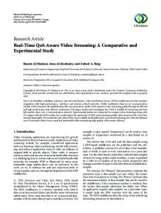
II. EXPERIMENT AND TRANSFER FUNCTION MODELLING 2.1 Experimental Process Figure 1. shows the setup for the experimental process. The major objective of the experiment is to capture hysteresis nonlinearity by acquiring input and output data. The PEA used in this experiment is AE0505D16DF, a resin coated type multilayer stack PEA by NEC Tokin. The actuator maximum driving voltage is 150V DC with a corresponding maximum output displacement of 17.4±2.0 μm [39]. Equipment used for conducting the experiment include: Olympus IX3-ICS inverted microscope attached to desktop computer, DC power supply unit, a laptop computer, stack-type piezoelectric actuator, microcontroller module and arduino microcontroller based signal switching circuit. DC power supply unit was used to generate the required voltage for driving the actuator, while the switching circuit connected to a laptop computer was used to generate different signal wave forms at different frequencies. Programs written in C programming language were programmed on the microcontroller using the laptop to generate the frequency and wave form of interest. Inverted microscope was used to capture the change in PEA tip position when the driving voltage changes. Fig. 2a shows the position of the PEA tip at an input of 125V as captured by the microscope, while Fig. 2b shows the tip position when the driving voltage was zero. With the DOI: 10.9790/1813-0610017586
www.theijes.com
Page 76
Preparation of Papers for the International Journal of Engineering and Science help of the microscope utility software known as DigiAcquis, a video was recorded at 25fps. The video was then converted to still pictures so that the frames at voltages of interest can be analyzed individually.
Figure 1: PEA Experimental platform
(a)
Actuator tip at 125V
Free space
Change in tip position
(b) Actuator tip at 0V
Free space
Figure 2: Piezoelectric actuator tip displacement monitoring using inverted microscope. (a) Tip at 125V input. (b) Tip at 0V input. The use of microscope was necessary in order to capture the very fine displacements of the PEA. When the actuator tip moves, it changes the area of the light reaching the magnification lens of the microscope. DOI: 10.9790/1813-0610017586
www.theijes.com
Page 77
Preparation of Papers for the International Journal of Engineering and Science Image processing techniques were used to determine the corresponding change in displacements when the driving voltage changes using the extracted frames. The PEA system was tested using different signal waveforms. Fig. 3b shows a triangular type input voltage that correspond to loading (increasing voltage) phase and unloading (decreasing voltage) phase, while Fig. 3a shows the corresponding change in tip position. The PEA was also tested with a square wave type input signal vibrating at a frequency of 1Hz with a duty cycle of 50% as shown in Fig. 4b, while Fig. 4a shows the corresponding changes in tip position for the actuator vibrating at 1Hz. 140
15
Loading Phase Unloading Phase
100 10
Voltage (V)
Tip Displacement (um)
120
80
60
5
40
20
0
0
5
10
15
20
25
30
35
40
45
0
50
0
5
10
15
20
Time (s)
25 Time (s)
30
35
40
45
50
7
70
6
60
5
50
Voltage (V)
Tip Displacement (um)
(a) (b) Figure 3: Input and output graphs for loading and unloading phases (a) Output graph (b) Input graph
4
3
40
30
2
20
1
10
0 0
50
Time (s)
100
150
0
0
50
Time (s)
100
150
(a) (b) Figure 4: Input and output graphs for vibrating piezoelectric actuator (a) Output graph (b) Input graph 2.2 Transfer Function Model Estimation To establish the transfer function of the PEA, 400 sets of input and output data points were collected. Using the system identification toolbox in MATLAB software, the transfer function model for the actuator was established. A 4th order model given by (1) was established with a 98.01% fitness to estimation data, Mean Squared Error (MSE) of 0.008147 and Final Prediction Error (FPE) of 0.032820. 3400 S 62060
(1) G S 4 S 572.5S 3 10120S 2 61670S 539200 The order of the transfer function given by (1) was reduced to 2nd order given by (2) by matching its time response characteristics to those of (1). By reformatting (2) in the form given by (3), mass, m, damping coefficient, b, and elastic constant, K, were obtained and presented in Table I. 7.4192 (2) G S 2 S 3.2S 64.5151
G S
DOI: 10.9790/1813-0610017586
1 mS 2 bS K www.theijes.com
(3)
Page 78
Preparation of Papers for the International Journal of Engineering and Science Table I: Piezoelectric actuator parameters Parameter Mass (m) Damping coefficient (b) Elastic constant (K)
Value 0.1348 0.4313 8.6957
Unit Kg N s/m N/m
2.3 Model Validation The validity of the transfer function model given by (1) was investigated based on residual analysis. The autocorrelation for the output displacement and cross correlation for voltage and displacement residuals are given by Fig. 5. It can be seen that, based on 99.9% confidence level (given by dotted lines), the model has passed validation tests. In Fig. 6, the model order reduction validity was investigated by comparing the step responses of the model given by (1) against the step response of the model given by (2). It can be seen that the models have same time response characteristics. 0.18
Autocorrelation 0.5
Reduced Order Model Original Model
0.16 0.14
0
-20
-15
-10
-5
0
5
10
15
20
1.5
Cross correlation
Amplitude
0.12 -0.5
0.1 0.08
1
0.06
0.5 0
0.04
-0.5
0.02 -1 -1.5 -20
0 -15
-10
-5
0
Samples
5
10
15
20
0
1
2
3
4
5
6
7
8
9
10
Time (seconds)
Figure 5: Model validation based on residual analysis on step
Figure 6: Model order reduction validation based response criteria
III. HYSTERESIS MODELING AND PARAMETER IDENTIFICATION 3.1 Bouc-Wen Hysteresis Model Formulation The dynamic equation of motion of a one degree-of-freedom (1-DOF) PEA can be expressed in the form given by (4) [40]. By considering the nonlinear hysteresis property of the PEA system without considering parameter uncertainties and unmodeled dynamics, equation (4) is modified and expressed in the form given by (5). Fig. 7 shows the representation of the PEA model with its various parameters and hysteresis property. It is assumed that one end of the PEA is fixed, and the order end is a free end, and can produce displacements along the longitudinal axis of the actuator when an input voltage is applied between the actuator's input terminals, m b k u (4) m b k k ( d eu h (t ))
(5)
where m, b, k, u, 𝜓, de and h(t) represent the mass of the system, viscous damping coefficient, elastic constant, excitation voltage, tip displacement, piezoelectric strain coefficient and hysteresis displacement of the system respectively. The parameters m, b, and k have been identified from the PEA transfer function obtained experimentally in section II and were tabulated in Table I. The hysteresis nonlinearity for n-degrees-of-freedom is modelled using the Bouc-Wen equation adapted for PEA given by (6) and (7). The other parameter, n, controls the smoothness of transition from elastic to plastic response. In this paper, hysteresis along the PEA longitudinal axis (d33) is our subject of interest, hence, the Bouc-Wen hysteresis equation given by (7) can be written as (8). The parameters α, β and γ define the shape, orientation and magnitude of the hysteresis loop respectively. The implementation of the Bouc-Wen hysteresis equation given by (7) in MATLAB/Simulink is as shown in Fig. 8. The entire dynamic simulation model implemented using (5), (6) and (7) is as shown in Fig. 9.
(t ) deu h(t ), (t0 ) 0 DOI: 10.9790/1813-0610017586
www.theijes.com
(6)
Page 79
Preparation of Papers for the International Journal of Engineering and Science n1 n h u u u h u h , h (t0 ) h0 h(t ) u u u u h Bouc-Wen
(7) (8)
𝜓
k
m
u
b Figure 7: Piezoelectric actuator model
Figure 8: Bouc-Wen hysteresis model simulation blocks
Figure 9: Complete PEA model with Bouc-Wen hysteresis model simulation blocks 3.2 Parameters Identification Using NM-Simplex Algorithm At this point, the parameters of the Bouc-Wen hysteresis model of the PEA were identified. The process of identifying optimum model parameter values is a challenging task. Hence, the identification problem becomes an optimization one. The goal is to minimize the objective function subject to constraints. Nelder-Mead Simplex method was used to identify optimum parameters for the Bouc-Wen model. The steps executed by Nelder-Mead simplex optimization process are as follow [41]: N 1 A simplex, S, is defined as a convex hull having N+1 number of vertices x j in N-dimensional space j 1
N given by . The vertices the condition that simplex hull volume is nonzero. NM algorithm starts iteration from an initial simplex. Kth iteration starts by ordering and labeling the current N 1 (k ) vertices as x j j 1
g1( k ) g 0( k ) g3( k ) ......... g N( k)1 (k )
(k )
The point x N 1 is referred as the best point, point x2 DOI: 10.9790/1813-0610017586
(9) (k )
as next to the worst, point x1
www.theijes.com
as the worst point. Page 80
Preparation of Papers for the International Journal of Engineering and Science Our goal is to minimize the cost point. For this reason, the worst point is then discarded, many 'better' trial points generated. Function values are computed at these generated points. A new simplex is then constructed having N+1 vertices by making use of rules that favour minimization of the objective function value. A single function evaluation is required when iteration process terminates after reflection or two evaluations for termination after an expansion, and N+2 evaluations for a shrinkage step. Iterations were performed and the solutions converged at the 262nd iteration. The Bouc-Wen model parameters trajectories are as shown in Fig. 10. The optimal values for the Bouc-Wen model parameters are given by Table II while Fig. 11 shows a comparison between measured data obtained experimentally against simulated data that was obtained from Bouc-Wen model (as far the optimum parameters). Table II: Identified Bouc-Wen model parameters Parameter Alpha (α) Beta (β) Gamma (γ) Piezoelectric Coefficient
Initial Guess 7.20 x 10⁻² 1.76 x 10⁻² 1.66 x 10⁻² 1.27 x 10⁻¹
Unit μm/V
Trajectories of Estimated Parameters
0.1 alpha
Optimum Value 8.09 x 10⁻² 3.80 x 10⁻³ -5.40 x 10⁻³ 2.06 x 10⁻¹
Alpha
0.05 0 0.02
gamma Parameter Values
beta
Beta 0.01 0 0.05
Gamma 0
-0.05 0.4 strain
Piezoelectric Coefficient 0.2 0 0
50
100
150
200
250
300
Iterations Iterations
Figure 10: Trajectories of Bouc-Wen model parameters 16
Measured data Simulated data
14 12
Displacement(um)
10 8 6 4 2 0 -2
0
20
40
60
80
100
120
140
Input Voltage (V)
Figure 11: Measured data and Bouc-Wen model simulated data compared
DOI: 10.9790/1813-0610017586
www.theijes.com
Page 81
Preparation of Papers for the International Journal of Engineering and Science IV. THE HYSTERESIS MINIMIZATION TECHNIQUES 4.1 Hysteresis Minimization Based on PID Control The PID controller algorithm is given (10). The error, e(t), is given by (11). This is the tracking error obtained as the difference between the command set-point (which is desired output displacement in our case) and the actual output (displacement which is hysteretic in nature) [42], d uc t K P e t K I e t dt K D e t (10) dt e t r (t ) (t ) (11) where is the desired displacement and is the actual displacement. This is to say, the hysteresis nonlinearity problem can be considered as the error that results in tracking the desired output displacement. The parameters and are proportional, integral and derivative gains of the PID controller respectively. These gains determine how much of the controller proportional (P), Integral (I) and derivative (D) -actions are needed. The control action, , is adjusted to minimize the error to near zero. The P-action dictates the current error reaction, I-action dictates the reaction of the sum of the current error and recent past errors while the D-action dictates the reaction due to the rate at which the error has been changing [42]. Increasing the P-action increases system speed, reduces steady state error (SSE) and may introduce overshoots (OS). Increasing I-action removes completely the SSE but increases OS. The D-action decreases OS and slows down the system. The error minimization is achieved by the weighted sum of the P,I and D actions. Figure 12 shows the simulation blocks for hysteresis minimization using PID control technique. The controller optimum and feasible tuning parameters gains were obtained using NM-simplex optimization technique. Simulink PID controller automatic tuning functionality was used to obtained initial guess for the values of these gains for the optimization process. The solutions for the gains converged at the 50th iteration. The values for the gains ( and ) are given by Table III. Table III: Optimized PID controller tuning gains Initial Guesses for Gains Optimal Gains KP KI KD KP KI KD 52.6280 70.6480 3.9813 50.1370 84.4050 3.9926 4.2 Hysteresis Minimization Based on Inverse Multiplicative Technique The structure of the control strategy is as depicted in Fig. 13. The objective of the control strategy is to have the desired tip displacement and actual tip displacement satisfy (12). r (t ) ( t ) 0 (12) In the literature, most model based hysteresis minimization techniques rely on computing an inverse hysteresis model. This is done by inversion of the identified hysteresis model to cancel hysteresis effect. Hysteresis model inversion usually involves additional computations. Additional work is required to compute the parameters of the inverse model. A control strategy for hysteresis cancellation that requires no additional computations is the inverse multiplicative minimization technique [37]. By writing h(t)=H(u), (6) can be written in reduced form given by (13). (t ) deu H (u ) (13) Let us consider the model given by (13). Using only the linear term deu, we extracted the value of u such that it satisfies the desired displacement, 𝜓r. We obtain: 1 (14) u H (u ) de r The compensator is given by (14). The input to the compensator is the desired (or reference) tip displacement 𝜓r. In addition, the compensator has an output u and a nonlinear feedback H(u). The only required inversion is that of de and is strictly positive. Since de and H(u) have been identified already, no further calculations were needed. For this reason, the compensator implementation was simple computation wise.
DOI: 10.9790/1813-0610017586
www.theijes.com
Page 82
Preparation of Papers for the International Journal of Engineering and Science Compensator
H(u)
uc
H(u)
h K
G(S)
𝜓
Bouc-Wen model PID
H(u)
T. Fcn.
+
𝒅𝒆
Bouc-Wen model
+
𝜓r 𝜓
𝜓r
Figure 12: Simulation block for PID controller based hysteresis minimization
+ +
𝟏 𝒅𝒆
G(S)
u
𝒅𝒆
h +
K
Figure 13: Inverse multiplicative hysteresis compensator structure
V. RESULTS AND DISCUSSIONS In this section, the results obtained based on the investigated hysteresis minimization techniques are presented. Hysteresis minimization results for rising and falling reference input tracking based on PID feedback technique and inverse multiplicative technique are given by Fig. 14 and Fig. 15 respectively. The tracking errors for the two techniques were compared in Fig. 16. Based on the results, it can be seen that, hysteresis minimization using Inverse multiplicative technique is more promising. To further support this argument, a quantitative comparison for the degrees of hysteresis minimization by both techniques based on IAE are given by Table IV. IAE integrates over time duration of the absolute deviation of the PEA actual tip displacement from desired tip displacement (setpoint). The IAE error value for the uncompensated hysteresis case was 67.73. Error results for PID and inverse multiplicative technique were 3.099 and 1.478 respectively. These values correspond to 95.42% and 97.82% reduction in hysteresis nonlinearity by PID and Inverse multiplicative technique respectively. PID control is the most popular control strategy, it is simple to implement and can be implemented without having full knowledge of the system (i.e. it does not require accurate model). However, feedback techniques being closed-loop controls require accurate sensors which can be bulky, slower, expensive or even not available. On the other hand, Inverse multiplicative technique being an open-loop technique requires no feedback sensors, hence, it is relatively cheaper and have faster response. However, it requires model and hence, can only be implemented when there is sufficient knowledge of the system under consideration. Furthermore, the effectiveness of the open-loop technique studied depends largely on the accuracy of the model.
VI. CONCLUSION Piezoelectric actuators are applied in high precision, general micro/nano positioning and manipulation applications as a result of their numerous advantages like, ultra-high precision, relatively low cost, low power consumption, small size and large generated force. However, a major setback for piezoelectric actuators is hysteresis nonlinearity which can result in large positioning inaccuracies. Hence, control engineers find hysteresis minimization techniques an interesting field to investigate. In this paper, hysteresis modelling was conducted based on Bouc-Wen model and parameters of the model were identified based on optimization technique. In this work, a comparative study of control strategies based on PID and Inverse multiplicative technique has been conducted. Degrees of hysteresis of hysteresis minimizations by the different strategies have been compared based on IAE. Based on IAE values, Inverse multiplicative technique offered better minimization as compared to feedback control using PID controller. However, Inverse multiplicative technique depends on model accuracy which may not be possible to be obtained. To further improve the research work, rate-dependent hysteresis should be considered.
DOI: 10.9790/1813-0610017586
www.theijes.com
Page 83
Preparation of Papers for the International Journal of Engineering and Science 16
Hysteresis minimization by PID
14
Displacem ent (um )
12 10 8 6 4 2 0 -2
0
20
40
60
80
100
120
140
Voltage (V)
Figure 14: PID tracking control response for loading and unloading phases 16
Minimization by inverse by multiplication
14
Displacem ent (um )
12 10 8 6 4 2 0 -2
0
20
40
60
80
100
120
140
Voltage (V)
Figure 15: Multiplicative Inverse tracking control response for loading and unloading phases
Table III: Hysteresis minimization techniques performance comparison based on IAE Minimization Technique Error (IAE) Residual Hysteresis Degree of Hysteresis None 67.73 100.00% 0.00% Optimized PID 3.10 4.58% 95.42% Inverse Multiplicative 1.48 2.18% 97.82%
DOI: 10.9790/1813-0610017586
www.theijes.com
Page 84
Preparation of Papers for the International Journal of Engineering and Science 0.1
PID Control Error Inverse Control Error
Error Am plitude (um )
0.05
0
-0.05
-0.1
-0.15
0
5
10
15
20
25
30
35
40
45
50
Tim e (s)
Figure 16: Tracking errors comparison for PID control and Multiplicative inverse technique
ACKNOWLEDGEMENTS The authors wish to express their profound gratitude to Associate Professor Dr. Mohd Ridzuan Bin Ahmad for his support.
REFERENCES [1] M. Rakotondrabe, K. Rabenorosoa, J. Agnus, and N. Chaillet, “Robust feedforward-feedback control of a nonlinear and oscillating 2DOF piezocantilever,” IEEE Trans. Autom. Sci. Eng., vol. 8, no. 3, pp. 506–519, Jul. 2011. [2] Y. Li and Q. Xu, “Adaptive sliding mode control with perturbation estimation and PID sliding surface for motion tracking of a piezodriven micromanipulator,” IEEE Trans. Control Syst. Technol., vol. 18, no. 4, pp. 798–810, Jul. 2010. [3] J. Liang, H. Chen, and L. Lin, “Model-Based Control for Piezoelectric-Actuated Systems Using Inverse Prandtl-Ishlinskii Model and Particle Swarm Optimization,” Int. J. Mech. Aerosp, Ind. Mechatron. Manuf. Eng., vol. 8, no. 3, pp. 613–618, 2014. [4] M. Špiller and Z. Hurák, “Hybrid charge control for stick–slip piezoelectric actuators,” Mechatronics, vol. 21, no. 1, pp. 100–108, 2011. [5] M. H. Rahman, A. H. M. Sulaiman, M. R. Ahmad, and T. Fukuda, “Finite Element Analysis of Single Cell Wall Cutting by Piezoelectric-actuated Vibrating Rigid Nanoneedle,” IEEE Trans. Nanotechnol., vol. 12, no. 6, pp. 1–9, Nov. 2013. [6] I. Obataya, C. Nakamura, S. Han, N. Nakamura, and J. Miyake, “Nanoscale operation of a living cell using an atomic force microscope with a nanoneedle,” Nano Lett., vol. 5, no. 1, pp. 27–30, 2005. [7] Z. Lu, X. Zhang, C. Leung, N. Esfandiari, R. F. Casper, and Y. Sun, “Robotic ICSI (intracytoplasmic sperm injection),” IEEE Trans. Biomed. Eng., vol. 58, no. 7, pp. 2102–2108, Jul. 2011. [8] T. H. Saleh, “Active Vibration Control of a Smart Beam Using LQR , PID and Fuzzy Logic Controllers,” M.S. thesis, Mech. Eng., University of Basrah, Iraq, 2014. [9] J. Enyu, Z. Xiaojin, G. Zhiyuan, and Q. Xiaoping, “Simulation And Research Of Active Structural Vibration Control Based On Optimal Control,” Amer. J. Eng. Technol. Res., vol. 15, no. 1, pp. 59–66, 2015. [10] S. K. Vashist and D. Chhabra, “Optimal placement of piezoelectric actuators on plate structures for active vibration control using genetic algorithm,” Int. J. Mech. Aerosp., Ind. Mechatronics Eng., vol. 7, no. 3, pp. 165–170, 2013. [11] L. Gao, Q. Lu, F. Fei, L. Liu, Y. Liu, and J. Leng, “Active vibration control based on piezoelectric smart composite,” Smart Mater. Struct., vol. 22, no. 12, pp. 1-12, 2013. [12] J. Peng and X. Chen, “A Survey of Modeling and Control of Piezoelectric Actuators,” Mod. Mech. Eng., vol. 03, no. 01, pp. 1–20, 2013. [13] M.-J. Yang, C.-X. Li, G.-Y. Gu, and L.-M. Zhu, “A Modified Prandtl-Ishlinskii Model for Rate-dependent Hysteresis Nonlinearity Using mth-power Velocity Damping Mechanism,” Int. J. Adv. Robot. Syst., vol. 11, no. 163, pp. 1–10, 2014. [14] D. Habineza, M. Rakotondrabe, and Y. Le Gorrec, “Modeling, identification and feedforward control of multivariable hysteresis by combining Bouc-Wen equations and the inverse multiplicative structure,” in 2014 Amer. Control Conf., 2014, no. 1, pp. 4771–4777. [15] D. Habineza, M. Rakotondrabe, and Y. Le Gorrec, “Bouc--Wen Modeling and Feedforward Control of Multivariable Hysteresis in Piezoelectric Systems: Application to a 3-DoF Piezotube Scanner,” IEEE Trans. Control Syst. Technol., vol. 23, no. 5, pp. 1797– 1806, Sept. 2015. [16] A. E. Charalampakis and V. K. Koumousis, “Identification of Bouc–Wen hysteretic systems by a hybrid evolutionary algorithm,” J. Sound Vib., vol. 314, no. 3, pp. 571–585, 2008. [17] G. O. García, “Identification of hysteretic structural systems using multi-objective optimization algorithms,” M.Eng. thesis, Elect., Electron. Eng. and Comput., Universidad Nacional de Colombia, 2013. [18] A. E. Charalampakis and C. K. Dimou, “Identification of Bouc–Wen hysteretic systems using particle swarm optimization,” Comput. Struct., vol. 88, no. 21–22, pp. 1197–1205, 2010.
DOI: 10.9790/1813-0610017586
www.theijes.com
Page 85
Preparation of Papers for the International Journal of Engineering and Science [19] C.-X. Cai, X.-D. Liu, Dong-Ning, and H.-J. Li, “Bouc-Wen Model Parameter Identification for Piezoelectric Actuator Using Chaos Particle Swarm Optimization,” Micro-Nano Technol. Xiv, vol. 562–565, pp. 516–521, 2013. [20] A E. Charalampakis and V. K. Koumousis, “Parameter Estimation of Bouc-Wen Hysteretic Systems Using a Sawtooth Genetic Algorithm,” in 8th Int. Conf. Computational Struct. Technol., 2006, pp. 1–14. [21] M. Zhou and J. Wang, “Research on hysteresis of piezoceramic actuator based on the Duhem model,” Sci. World J., vol. 2013, pp. 16, 2013. [22] Z. Chi, M. Jia, and Q. Xu, “Fuzzy PID Feedback Control of Piezoelectric Actuator with Feedforward Compensation,” Math. Probl. Eng., vol. 2014, pp. 1-14, 2014. [23] Y. Xiao, Shunli and Li, “Modeling and High Dynamic Compensating the Rate-Dependent Hysteresis of Piezoelectric Actuators via a Novel Modified Inverse Preisach Model,” IEEE Trans. Control Syst. Technol., vol. 21, no. 5, pp. 1549–1557, 2013. [24] L. Riccardi, D. Naso, B. Turchiano, and J. and D. K. P. Janocha, Hartmut, “On PID control of dynamic systems with hysteresis using a Prandtl-Ishlinskii model,” 2012 Amer. Control Conf. (ACC), 2012, no. 2, pp. 1670–1675. [25] M. Yang, G. Gu, and L. Zhu, “Parameter identification of the generalized Prandtl–Ishlinskii model for piezoelectric actuators using modified particle swarm optimization,” Sensors Actuators A Phys., vol. 189, pp. 254–265, 2013. [26] Y. Liu, J. Shan, U. Gabbert, and N. Qi, “Hysteresis and creep modeling and compensation for a piezoelectric actuator using a fractional-order Maxwell resistive capacitor approach,” Smart Mater. Struct., vol. 22, no. 11, p. 1-12, 2013. [27] N. Miri, M. Mohammadzaheri, L. Chen, S. Grainger, and M. Bazghaleh, “Physics-based modelling of a piezoelectric actuator using genetic algorithm,” in 2013 IEEE Symposium on Ind. Electron. Applicat., 2013, pp. 16–20. [28] S. Rosenbaum, M. Ruderman, T. Ströhla, and T. Bertram, “Use of Jiles-Atherton and preisach hysteresis models for inverse feedforward control,” IEEE Trans. Magn., vol. 46, no. 12, pp. 3984–3989, 2010. [29] B. Vaseghi, D. Mathekga, S. Rahman, and A. Knight, “Parameter Optimization and Study of Inverse J-A Hysteresis Model,” IEEE Trans. Magn., vol. 49, no. 5, pp. 1637–1640, 2013. [30] Y. Iskandarani, H. R. Karimi, and M. R. Hansen, “An Iterative Based Approach for Hysteresis Parameters Estimation in Magnetorheological Dampers,” in 2012 6th IEEE Int.l Conf., 2012, pp. 439–444. [31] M. Peimani, “Parameter Estimation in Hysteretic Systems Based on Adaptive,” J. Inf. Syst. Telecommun., vol. 1, no. 4, pp. 217–222, 2013. [32] S. Talatahari, H. Mohaggeg, K. Najafi, and A. Manafzadeh, “Solving Parameter Identification of Nonlinear Problems by Artificial Bee Colony Algorithm,” Math. Probl. Eng., vol. 2014, no. 1, 2014. [33] R. Svečko and D. Kusić, “Feedforward neural network position control of a piezoelectric actuator based on a BAT search algorithm,” Expert Syst. Appl., vol. 42, no. 13, pp. 5416–5423, 2015. [34] S. K. S. Fan and E. Zahara, “A hybrid simplex search and particle swarm optimization for unconstrained optimization,” Eur. J. Oper. Res., vol. 181, no. 2, pp. 527–548, 2007. [35] B. Jayawardhana, H. Logemann, and E. P. Ryan, “PID control of second-order systems with hysteresis,” in Proc. IEEE Conf. Decision Control, 2007, pp. 4626–4630. [36] S. Xiao and Y. Li, “Dynamic compensation and control for piezoelectric actuators based on the inverse Bouc–Wen model,” Robot. Comput. Integr. Manuf., vol. 30, no. 1, pp. 47–54, 2014. [37] M. Rakotondrabe, “Bouc-Wen Modeling and Inverse Multiplicative Structure to Compensate Hysteresis Nonlinearity in Piezoelectric Actuators,” IEEE Trans. Autom. Sci. Eng., vol. 8, no. 2, pp. 428–431, 2011. [38] Y. Li, Z. Liu, and Y. Liu, “Hysteresis Modeling of Piezoelectric Actuators and Feed-Forward Compensation Algorithm Research,” Int. J. Control Autom., vol. 8, no. 7, pp. 405–416, 2015. [39] NEC TOKIN Corporation, “Multilayer Piezoelectric Actuators,” vol. 08, 2015, pp. 6-7. [40] M. Motamedi, S. M. Rezaei, M. Zareinejad, and M. Saadat, „Robust control of a piezoelectric stage under thermal and external load disturbances,” in 2009 Amer. Control Conf., 2009, pp. 2260–2265. [41] Q. Xiong and A. Jutan, “Continuous optimization using a dynamic simplex method,” Chem. Eng. Sci., vol. 58, no. 16, pp. 3817– 3828, 2003. [42] B. Nagaraj and N. Murugananth, “A comparative study of PID controller tuning using GA, EP, PSO and ACO,” in 2010 IEEE Int. Conf. on Commun. Control Comput. Technol. (ICCCCT), 2010, pp. 305–313.
Shehu Muhammad Auwal. “A Comparative Study of Open-Loop and Closed-Loop Control Schemes for Hysteresis in a d33-Mode Piezoelectric Actuator.” The International Journal of Engineering and Science (IJES), vol. 6, no. 10, 2017, pp. 75–86.
DOI: 10.9790/1813-0610017586
www.theijes.com
Page 86