International Journal of Advanced Biotechnology and Research (IJBR) ISSN 0976-2612, Online ISSN 2278–599X, Vol-7, Special Issue3-April, 2016, pp645-650 http://www.bipublication.com Case Report
A Comparative Study on a Tilt-Integral-Derivative Controller with Proportional-Integral-Derivative Controller for a Pacemaker Aysan Esgandanian1* and Sabalan Daneshvar 2 1 Department of Biomedical Engineering, East Azarbayjan Science and Research Branch, Islamic Azad University, Tabriz, Iran 2 Faculty of Electrical Engineering, University of Tabriz Tabriz, Iran *Corresponding author: Email:
[email protected], Tel: +98-9126065160
ABSTRACT: The study is done to determine the comparison between proportional-integral-derivative controller (PID controller) and tilt-integral-derivative (TID controller) for cardiac pacemaker systems, which can automatically control the heart rate to accurately track a desired preset profile. The controller offers good adaption of heart to the physiological needs of the patient. The parameters of the both controllers are tuned by particle swarm optimization (PSO) algorithm which uses the integral of time square error as a fitness function to be minimized. Simulation results are performed on the developed cardiovascular system of humans and results demonstrate that the TID controller produces superior control performance than PID controllers. In this paper all simulations were performed in Matlab. Keywords: integral of time square error, pacemaker systems, proportional-integral-derivative controller, PSO algorithm, tilt-integral-derivative controller
[I]
INTRODUCTION The main purpose of biomedical engineering is healthcare, thereby improving patient’s quality of life. Out of the various techniques, the primary focus is to build a trustworthy and optimized method for electro simulation of heart [1]. The advance of patient's quality of life is the focal factor in the development of new and optimized methods in the recent decades. The present work describes the design of a novel control system which regulates the heart rate (HR). This control system is a cardiovascular system which is operated in closed loop manner with unity negative gain in the feedback path [2]. Cardiovascular diseases are recently major causes of morbidity and mortality in the developed countries. Cardiac disorders don’t have
identifiable factors that cause impermanent depression of cardiac impulse arrangement and conduction, such as drugs, electrolyte or endocrine imbalances, infection or the acute phase of myocardial infraction. Attention must be given to the cardiac rhythm disturbance before a proper management. Diagnosis of human abnormalities is very important for improving the patient’s quality of life. Early diagnosis and medical treatment by measuring the changes in the pattern of heart electrical properties of heart disease can saved from serious health problems and prevent the sudden death of a patient. There have been important changes in assessment of patients with chest pain and doubted myocardial injury in the past decade. Electrocardiography (ECG) is the
A Comparative Study on A Tilt-Integral-Derivative Controller with Proportional
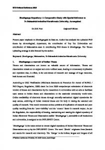
most commonly used diagnostic technique myocardial ischemia and infraction which is recommended by world health organization (WHO). The changes in HR depend on physiological needs of the patient and easy personalization. By computing R-R interval of ECG heart rate can be measured. Usually natural pacemaker of heart synchronizes rhythm of heart. A pacemaker is used, if there is any problem condition system of heart. It employs an electrical impulse once it observes any ambiguity in the heart rate which may happen due to changes in electrical activity of the heart [3]. Implantable cardiac devices such as pacemakers are widely used nowadays. They have become a therapeutic tool with more than 250000 pacemaker implants every year [4].Fig1 demonstrates a block diagram of the implantable pacemaker integrated circuit (IPIC). The ECG detector checks the HR and rhythm with the digitalized ECG signals from an analogue-to-digital converter (ADC). When an abnormal HR is observed, electrical stimulations are applied to the heart using the high-voltage multiplier and pulse generator. In addition, once it is implanted inside human body, the pacemaker is expected to operate over several years without changing the battery to avoid repeated surgeries due to battery exhaustion, low power consumption is another extremely important design requirement for IPIC [5].
figure 1 Implantable Pacemaker
The present work presents the comparison of the design and analysis of two control systems for regulating the HR using pacemaker in an efficient Aysan Esgandanian and Sabalan Daneshvar
nowadays employed in the recognition of way. The control system in this work is reckoned to be composed of cardiovascular system energized by one pacemaker system as worked in a closed loop manner with integrity negative gain in the closed loop feedback path [6]. The design emphasizes on the optimality in operation which is determined by using a compensator .In this paper, a mathematical model of cardiovascular system using transfer function has introduced. Then, a closed loop pacemaker by using TID controller instead of PID controller for regulating the mixing venous oxygen saturation level has introduced and analysed a control system for regulating the HR using pacemaker in an efficient way. Recently, simulation aspects of artificial pacemaker have done. System for both controllers by the results that we have obtained from simulation in MATLAB/Simulink. [II] PRESENTATION OF THE SYSTEM 1.1. Pacemaker A medical device called pacemaker regulates the rhythmic action of heart using electrical impulses. The impulses will be delivered by electrodes which will be in close interaction the heart muscles. A pacemaker originates from an electronic unit for generating impulses and a lead to carry the generated impulses to the heart. The electrode arrangement is in the form of bipolar or unipolar system. In bipolar system, two electrodes are placed on the heart itself while in unipolar system, one electrode is placed on the heart while the other electrode will be placed anywhere in the body. Basically, pacemaker classified into two main types: External pacemaker: used when heart block occurs as an emergency and will exist only for a short period of time. Internal pacemaker: used as a long term pacing because of permanent damage which prevent heart from normal triggering [1]. Generally pacemaker has two functional units: Sensing circuit: it senses the patient’s HR Output circuit: it sends out electrical signals to heart muscles [2] 646
A Comparative Study on A Tilt-Integral-Derivative Controller with Proportional
This electrical signal is used to control the HR of the patient. If patient HR becomes too slow (bradycardia) or rapid (tachycardia),the pacemaker senses the abnormal signal and start sending a regular excitation signals to heart muscles which pushes the heart to contract at a rate fast enough (for bradycardia) and slow (for tachycardia) the patient’s heart rhythm normal. The primary objective of a pacemaker is to treat abnormalities in heart rhythm and to maintain an adequate HR. Pacemaker helps a person with abnormal heart rhythm to resume normal lifestyle. Modern pacemakers allow cardiologists to select the required pacing mode for individuals since they are externally programmed. Reliability of modern pacemakers allows them to be used not only for pacing but also for other diagnostic purposes [4]. Therefore, much more improved rate-adaptive pacemakers than former ones were made in virtue of combining microprocessor technology and improved algorithms combined with various sensor technologies although there was no fundamental advance in a field of sensor technology for several decades [7]. Pacemakers can be used for continuous cardiac monitoring and for treating problems related with rhythm of heart beat, as they provides electrical stimuli to chambers of heart to maintain proper rate. During irregular rhythm of heart (arrhythmia); the heart will not be able to pump enough blood for satisfying the oxygen needs of the body. Pacemakers can determine the time external stimuli must be given to the heart by calculating the time of incoming contraction of heart muscles. Pacing systems usually have three main parts: Pacemaker with the body sensors Pacing leads carrying pacing impulses Programmer Pacemaker uses low energy electrical pulses to overcome the faulty functioning of heart Pacemaker can: Speed up slow heart rhythm Help control variations in heart rhythm Make sure the ventricles contract normally
Aysan Esgandanian and Sabalan Daneshvar
Coordinate electrical signalling between the upper and lower chambers of the heart Coordinate electrical signalling between the ventricles [1]. 1.2. PID Controller The proportional Integral Derivative Controller is the widely used feedback controller. The input of the PID controller is an error value which is the difference between measured process variable and desired set point. The PID controller algorithm has three constant parameters: Proportional term [P] : depends on the present error Integral term [I] : depends on accumulation of past errors derivative term [D] : prediction of future errors The output u(t) of the PID controller is given by: C (s) K p Ti S 1 TS
(1)
figure 2 Block Diagram of PID Controller
Providing an improved feedback loop compensator having the advantages of the conventional PID compensator provides a response which is closer to the theoretically optimal response. This object, and other general objects, are achieved by the provision of a threecomponent tuneable feedback loop control system having a PID-type compensator wherein the proportional compensating unit is replaced with a compensator having a transfer 1 n .This function characterized by s compensator is herein referred to as a “Tilt” compensator, as it provides a feedback gain as a function of frequency which is tilted or shaped 647
A Comparative Study on A Tilt-Integral-Derivative Controller with Proportional
with respect to the gain frequency of a conventional or positional compensation unit. The entire compensator is herein referred to as a TiltIntegral-Derivative (TID) compensator. For the Tilt compensator, n is a nonzero real number, preferably between 2 and 3. Thus, unlike the conventional PID controller, wherein exponent coefficients of the transfer functions of the elements of the compensator are either 0, - 1, or + 1, the invention exploits an exponent coefficient 1 .By replacing the conventional by s proportional compensator with the tilt compensator of the invention, an overall response is achieved which is closer to the theoretical optimal response determined by Bode. In accordance with a preferred embodiment of the invention, the integral portion of the compensator has a transfer function characterized by 1 , and s the derivative portion of the compensator has a transfer function characterized by s. The three components of the compensator are connected in parallel along a control line between a summer which receives and sums a control signal from a plant with a feedback signal received along a feedback path, and an actuator or control unit which controls the plant in response to the compensated control signal output from the compensator. Also in accordance with the preferred embodiment, a prefilter is provided along the command signal path prior to the summer for prefiltering the command signal. A preferred transfer function for the prefilter is: C (s) Ti S
1
TtS
1 n
T S
scalar gains. Preferably, each of the three paths has the phase shift and the slope of the gain response frequency independent. This provision helps ensure that the TID compensator is universal with respect to the plants with different bandwidths, i.e., the controller is easily implemented in feedback systems which previously employed a PID controller. By providing each of the paths of the threecomponent compensator of the invention with a transfer function characterized by s or a power of s, the phase shift and slope of the gain response are both rendered frequency independent, thus ensuring that the compensator is substantially universal [8].Tilt-Integral-Derivative Controllers or TID Controllers as it is clear of its name, as illustrated in Fig. 2, are just like PID controllers wherein the Proportional part of the controller is replaced with is replaced with a tilted component
1
with the transfer function of S n TID controllers have simpler tuning, better disturbance rejection ratio, and smaller effects of plant parameter variations, comparing to PID Controllers. The objective of TID Controller is to provide an improved feedback loop compensator having the advantages of the conventional PID Controller, but providing a response which is closer to the optimal response [9]. The transfer function of the proposed controller is shown in Equation (2).
(2)
The TID compensator of the invention, particularly in combination with the prefilter, achieves a feedback control response which is improved over the response of a conventional PID compensator. However, the TID compensator of figure 3 TID Controller block diagram the invention retains many of the advantages of the conventional PID compensator, including ease PSO ALGORITHM in tuning. Further, the TID compensator retains [III] The PSO algorithm is an evolutionary the general structure of a PID compensator by optimization algorithm introduced by Kennedy employing three parallel paths having tuneable Aysan Esgandanian and Sabalan Daneshvar
648
A Comparative Study on A Tilt-Integral-Derivative Controller with Proportional
and Eberhart. Development of this algorithm was In this study, Integral of Time Weighted motivated by animal social behaviours such as Squared error (ITSE), is used as a fitness function. schools of fish or flocks of birds and the way these The purpose of the GA is to find the TID and animals find food sources and avoid predators. FOPID controllers parameters which minimize the These organisms are striking and many of their ITSE criteria. features have an apparent usefulness. These Mathematical description of the ITSE is given organisms are the results of much iteration in a below where is the error signal. grand optimization algorithm. This optimization t 2 ITSE = te ( t ) dt (5) has happened in genes of the living creatures. So 0 like most of the smart optimization algorithms, the The population of the algorithm has been PSO Algorithm, is inspired from the nature. selected 100, and the answer is converged in less The structure of the PSO algorithm, using than 5000 function evaluations [10]. random numbers, is organized as follows: Step 1 refers to the initializing population, [IV] SIMULATIONS where the random number is generated to A simulation has been done in Matlab/Simulink become a starting position for the motif environment. Fig. 4 demonstrates the block candidate or particle of each sequence. diagram of the whole system with PID controller. Step 2 refers to the calculation of the fitness value for each individual particle, and parameter pBest will store the highest fitness value for that particle. Step 3 refers to the updating of the global highest fitness value (gBest). Step 4 refers to the calculation of velocities using a randomization technique. Step 5 refers to the updating of the new figure 4 The presentation of the system position of each particle by using a velocity Figure 5 demonstrates the response of the value. system by PID and TID controllers. The controller Step 6 refers to the termination condition, parameter have determined by PSO algorithm. where the process flow will be terminated if the condition is met; otherwise repetition will continue from Step 2. Mathematical representations of steps 4 and 5 (the velocity and position of the particles) are given below in which i is the number of the particle, d is the dimension, c1 and c2 are the acceleration constant of the velocity, w is the inertia weight, and at last r1 and r2 are the uniformly random numbers.
Vid W Vid C1 r1 (Pid Xid) c 2 r 2 (Gid Xid) (3 X(I 1)d Xid Vid
Aysan Esgandanian and Sabalan Daneshvar
(4)
figure 5
The diagram of pulse-time
As it shown the differences of the PID and TID controllers which illustrates better performance for TID controller.
649
A Comparative Study on A Tilt-Integral-Derivative Controller with Proportional
As it is shown in the following table. Mp, Tr and ITSE has calculated in table I. [Table-1].Comparison of PID and TID controllers Mp Tr ITSE PID 11.1 6.48 5.43 TID 11 7.2 4.3
[V]
CONCLUSION Pacemaker performance depends not only on pacemaker circuitry but also on the performance of the controller. In the present work PID and TID control techniques are analyzed to design heart rate controller. The PID controllers thus tuned do not supply the satisfactory response. Our idea is to present a clearer and more logical framework for cardiac pacemaker design which is simple to implement while processing fundamental basis. Instead of fixing a control structure and then attempting extract optimality from this controller, our approach will be to postulate a model, state desirable control objective and from these, proceed in a straightforward manner to obtain both the appropriate controller structure and parameters. A simulation was done in Simulink/Matlab to see the effectiveness of controllers. As it is shown in table I, TID controller has less overshoot and rise time. Also ITSE of the system with TID controller is less than the time of a PID controller is used. Steady state errors of both controllers are low, but again error of the system which contains TID controller is approximately 0, while PID controller has a steady state error about 1%. This fast convenient response can help the pacemaker work more efficiently.
Applications, vol. 36, no. 7, pp. 22-29, December 2011. 3. L.S. Dreifus, C.Fisch, J.C. Griffin, P.C. Gillette, J.W. Mason, and V. Parsonnet, “Guidelines for implantation of cardiac pacemakers and antiarrythmia devices,” AHA Medical/Scientific Statement, Special Report, pp.455-467, July 1991. 4. W. V. Shi, M. Zhou, “Body sensors applied in pacemakers: a survey,” IEEE, vol.12, no. 6, pp. 1817-1827, June 2012. 5. Y. J. Min, H. K. Kim, Y. R. Kang, G. S. Kim, “Design of wavelet-based ECG detector for implantable cardiac pacemakers,” IEEE, Trans, vol. 7, no. 4, pp. 426-436, July 2013. 6. B. Neogi, R. Ghosh, U. Tarafdar, A.Das, “Simulation aspect of an artificial pacemaker,” International Journal of Information Technology and Knowledge Management, vol. 3, no. 2, pp. 723-727, December 2010. 7. J. W. Shin, J. H. Yoon, Y. R. Yoon, “ A study on the rate-adaptive pacemaker by motion and respiration using neuro-fuzzy,” IEEE, vol. 2, pp. 992-994, July 2000. 8. W. V. Shi, M. Zhou, “Body sensors applied in pacemakers: a survey,” IEEE, vol.12, no. 6, pp. 1817-1827, June 2012. 9. B. J. Lurie, “Three-parameter tunable tiltintegral-derivative (TID) controller, United States Patent, USA, 1994. 10. J. Kennedy and R. Eberhart, "Particle Swarm Optimization," presented at IEEE International Conference on Neural Networks, Perth, Australia, 1995.
REFERENCES 1. K. R. Govind, R. A. Sekhar, “Design of a novel PID controller for cardiac pacemaker,” IEEE, Advances in Green Energy (ICAGE), pp. 82-87, December 2014. (references) 2. J. Yadav, A. Rani, G. Garg, “Intelligent heart rate controller for cardiac pacemaker,” International Journal of Computer
Aysan Esgandanian and Sabalan Daneshvar
650