Jun 2, 1995 - A Comparison of Three Functional. Modeling Methods. - R. Irehvije, M. Modarres, M. Lind. A. JAMES CLARK SCHOOL OF ENGINEERING.
CTRS-B9-02 Vol. B9 No. 02
June, 1995
A Comparison of Three Functional Modeling Methods - R. Irehvije, M. Modarres, M. Lind
A. JAMES CLARK SCHOOL OF ENGINEERING UNIVERSITY OF MARYLAND AT COLLEGE PARK
A COMPARISON OF THREE FUNCTIONAL MODELING METHODS
Reza lrehvije Center for Reliability Engineering University of Maryland College Park, MD, USA
Mohammad Modarres Center for Reliability Engineering University of Maryland College Park, MD, USA
ABSTRACT Functional Modeling is a new technique for describing and representing complex system. Unlike other traditional modeling techniques, functional modeling represents a complex system by its goal(s) and functions. The term "complex system" covers a wide rang of systems from software to nuclear power plants. The knowledge representation of a complex system is essential in every stage of the system's evolution (e.g. design, control, use, maintenance, diagnosis, or repair). Each of these stages concern with some aspects of the system and, therefore, it is important that the knowledge representation is sound and complete. This paper addresses the characteristics of three different functional modeling methods, namely GTST-MPLD, MFM, and RCS. These methods are compared in the context of one application: the Automated Guided Vehicle system (AGV).
I. INTRODUCTION Complex systems can be described in many different ways. The conventional way of describing a system is by applying the physical laws of the system mathematically. Theoretical knowledge, that is knowledge of scientific laws and principles, has been the basis of modeling complex systems for years. However, the use of such knowledge has, until recently, been restricted to numerical description, usually in form of differential or difference equations. A typical disadvantage of these type of syst.em description is that as the complexity of systems grows, the equations become more complicated and soon surpasses our computational capability and human comprehension. Another limitation of using this fom1 of description is that it is restricted to determining or predicting the exact behavior of the system. The science requires that the "intentions" and "purposes" of the system be determined. However, the traditional modeling methods do not provide any information about system intentions. In recent years, the science of Artificial Intelligence, (Al), has provided
Morten Lind Institute of Automated Control System Technical University of Denmark Lyngby, 2800, Denmark
new methods for describing complex systems with respect to their intentions and purposes. TI1e Al community has utilized techniques that allow complex knowledge to be represented adequately and used to generate qualitative descriptions of the system and its behavior. One of the techniques utilized by the Al society is Functional Modeling, (FM). l'unctional modeling has been used in various science disciplines and in different fomis. In general, functional modeling is capable of describing a system's intentions by giving information about the system goals, functions, components and their relationships. Depending on the type of analysis used to construct a functional model, the model may vary in its information content, and consequently be used for different applications. for example they can be used for design, diagnostic, event prediction or action planning for complex systems. Functional modeling is based on the assumption that all systems and their subordinates have specific objectives and, therefore represent the system in terms of its goal, function, component, behavior and properties, and the relation ship between them . This paper compares three functional modeling approaches, namely, Goal Tree Success Tree-Master Plant Logic Diagram, (GTST-MPLD) [I], Multilevel Flow Modeling,(Ml'M) [2], and Real-Time Control System, (RCS) L4], applied to an Autonomous Guided Vehicle system, AGV system. The comparison will result in an indication of similarities and the differeuces between the three methodologies.
II. AGV SYSTEM DESCRIPTION An Autonomous Guided Vehicle, AGV ,is a vehicle which movements is controlled by computer. The ideal form of an AGV collects necessary information from its environment and uses these information for planning of future action. The action is then preformed through the system's actuators. The system used for analysis is Autonomous Land Vehicle, developed by National Institute
Of standards and Technologies, NIST [6 ,7,8) . The system developed by NIST uses a mixed control system, i.e. the control of the system is shared between an operator and the vehicle's computer. The vehicle chosen for the program is the High Mobility Multi-purpose Wheeled Vehicle, HMMWV (pronounced hum-vee). A standard HMMWV's has been modified by the addition of actuators to permit computer control of steering, service brakes, parking brake, throttle, transfer case gear and transmission gear selection, engine start, lights and horn . The AGV system is composed of the following: OfT-board Controller: This is the computer that is used to tele-operate the vehicle. It consists of a number of controls and status displays. It includes a data radio that is used to send commands to the vehicle and receive status information back. It also includes a video receiver and display that are used to drive from. On-board Controller: The on-board controller contains the computer system that is used to control and coordinate the operation of the vehicle ru1d its sub-systems. It contains the radio drivers used to communicate with the off-board controller and its video display. Generally the on-board controller knows the vehicle location, can interpret commands received from the off-board controller, and can monitor the on-board safety devices. Interface Electronics Box: The interface electronics box contain all the electronic hardware to condition the signals from the various vehicle sensors. It contains the amplifiers for the various actuators on the vehicle. Sensor data is conditioned and passed along to the on-board controller, and command signals from the on-board controller are fed to the various actuators. TI1e interface box has a selection from panel controls that allow the user to enable or disable specific actuators, and to generate some simple control signals to some of the actuators. Safety System: The safety system provides a redundant system for stopping the vehicle in the event of a system malfunction or operator error. It contains a radio · receiver that receives a signal from the safety radio . It has direct control of the parking brake and can command the interface electronics box to halt the vehicle (overriding computer control of the vehicle.)
actions of the vehicle actuators, and various other vehicle sub-systems. TI1ere are also modifications to the electrical system of the vehicle that allow the control of such things as the horn, head-lights and ignition. Communication Unit: It is essential for the individual vehicle to be able to communicate with the main-system controller. TI1e vehicle must be able to receive such commands as work assignment, destination, rout, frequency , speed, when to start or stop and auxiliary equipment commands. Similarly the vehicle must be able to transmit its status to the system controller by sending information such as vehicle's identification, location, direction of travel, speed of travel, and others. Instructions to the vehicle microcomputer are usually generated by the off-board controller and then relayed to the vehicle. Likewise, the vehicle communicates its status back to the area controller. Data communications between the vehicle and the remote computer is provided by a spread-spectrum data radio. Another radio is used to supply video to the off-board computer.
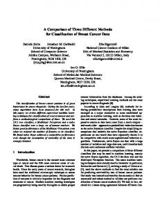
Ill. FUNCTIONAL MODELING METHODOLOGIES The first methodology to be discussed is "Goal Tree Success Tree and Master Plant Logic Diagram", (GTSTMPLD), presented by Modarres [I]. It employs logical connectors to describe the functional hierarchy of the system. TI1e second methodology is "Multilevel Flow Modeling", (MFM). MFM was presented by Lind[2,3] and is based on the flow of material, energy and infonnation in a complex system. TI1e last methodology is "Real-Time Control System", (RCS). RCS is developed by NIST [4,5), for real-time control system. All three methodologies use complex system's goals and function as the basis for modeling. A) Goal Tree Success Tree-Master Plant Logic Diagram GTST-MPLD is a methodology which uses system goals, functions, and component as entities to represent complex systems. As the name of this methodology indicates, it is composed of two part GTST and MPLD. I. GTST
Sensor and Actuators Package: The sensor and actuator package allows the on-board computer system to control the operation of the vehicle and sense its state. There are mechanical actuators attached to the steering, brake, throttle, transmission shift lever, transfer case shift lever, and the park brake. There are sensors that allow the computer to monitor the most of the dash indicators, the
The GTST is divided into two part: the Goal Tree, GT and the Success Tree, ST. The GT is concerned with the goals and functions which must be achieved by the system The GT starts with the system's "objective" at the top. The "objective" is then decomposed into a sufficient set of "subgoal"s, the achievement of which is necessary for the
Conuolling Vehicle
Multilevel Flow Modeling Con c epts Mass lmerprct& Execute Comm:111ds
Prov1dinc Off-boa.rd Coouoller with sensory Oac:i
Movement Co111rolling
~fonuoring
Vehicle Equipmen1
Providing Builc-in Oi:igoosuc
Energy
Colli~1on
Avt>id;ince
Source
Sink
........
8 .... ,, ® ,....., 0 0 0)
I • I