FACS 2007
A Component Model for Trustworthy Real-Time Reactive Systems Development Vasu Alagar1 ,2 Mubarak Mohammad1 ,3 Department of Computer Science and Software Engineering Concordia University Montreal, Quebec, Canada H3G 1M8
Abstract In this paper a formal description of trustworthy real-time reactive components is given. Component templates are defined and components are defined as instances of a template. A template consists of a structure part and a contract part. All components of a template share the structural and contractual properties while differing in their architectural descriptions and implementations. The behavior of a component is behavior of the architecture associated with the component and it is generated dynamically. Safety and security are identified as the two essential elements of trustworthiness. A rule for composing components is formalized. A brief comparison with SOFA 2.0 model and a discussion of our current research directions are included. Keywords: Component, Real-Time Reactive Systems, Safety, Security, Composition
1
Introduction
In this paper we determine safety and security as the two criteria of trustworthiness for RTRS and propose a formal approach to develop a trustworthy system. The development methodology is based on component technology. The goal is to formalize a trustworthy component and define a composition that preserves the requirements of safety and security. Reactive systems belong to the class of computer systems that maintain continuous interaction with their environment through stimulus and response. The class of reactive systems in which the reaction to a stimulus may be strictly regulated by timing constraints is called real-time reactive systems (RTRS). This type of systems has become an essential part of the technological infrastructure of modern societies. It is being used for a long time in safety critical missions, many directly affecting the environment and lives of people. Such systems are required to be trustworthy due to its complexity and the critical contexts in which they operate. 1
This research is supported by a Research Grant from Natural Sciences and Engineering Research Council of Canada.(NSERC) 2 Email:
[email protected] 3 Email: ms
[email protected]
This paper is electronically published in Electronic Notes in Theoretical Computer Science URL: www.elsevier.nl/locate/entcs
Alagar and Mohammad
Trustworthiness is the system property that denotes the degree of user confidence that the system will behave as expected [10,23]. In order to trust the system, the trustworthiness credentials of the system should be examined before granting the trust. The challenge in building provably trustworthy RTRS lies in combining safety and security requirements. Research in verifying safety and security properties have progressed in parallel, due to the finding that safety and security can’t be formally specified and verified together in any one formal method [18,27,16]. We suggest the use of component-based development (CBD)[26] as a basis for a unified formal model for the specification and verification of safety and security properties of RTRS. CBD is the type of software engineering development in which systems are built by constructing units, called components, that perform simple tasks, and assembling them to create composite components that perform complex tasks. Some potential benefits of applying CBD for RTRS include complexity reduction, time and cost savings, predictable behavior, and productivity increase [10]. In the literature, there is an inconsistency in defining components between un-timed and real-time component models. On the one hand, there is a common agreement [10,22,26] that component specification should include both structural and behavioral description. Structural description includes, but not limited to, specifying interfaces, connectors, and composition. These are central concepts in CBD. An interface defines access points to the services provided/requested by components. A connector is a special component that defines the communication between two components. Composition allows building systems by connecting existing components in such a way that preserves their essential properties. On the other hand, in current component-based models for real-time systems, a component is modeled as timed automata [5], duration automata [15], extended finitestate machine [12], and finite-state process [11]. Such modeling techniques focus only on the behavioral aspect and makes no distinction between object-oriented and componentbased models. Other real-time component models [9] define ”flat” components with restrictive execution model as opposed to hierarchical components found in general un-timed component-based models [4,21]. This shows that there is no uniform specification notation yet for describing un-timed and timed systems. Moreover, all the component models presented focus mainly on safety and liveness properties and don’t provide a formal foundation for the specification and verification of secure components. We propose a component model that collectively addresses the requirements of RTRS and credentials of trustworthiness. A central challenge in building trustworthy systems [20,23] using CBD method is composing trustworthy components so that the composed component is trustworthy . The main contributions of this paper are (1) a definition of the requirements of a component model for developing trustworthy RTRS, (2) a formal definition for trustworthy hierarchical RTRS components, and (3) a compositional theory for composing the structure and contract specification of trustworthy components. To the best of our knowledge there seems to be no published work that has combined safety and security in a provably correct manner in the development of trustworthy systems.
2
Requirements of a Component Model for Trustworthy RTRS
In this section, we state the requirements of RTRS, elements of trustworthiness, and elements of a component-model. We discuss how CBD can be used to effectively implement 2
Alagar and Mohammad
the requirements of RTRS and trustworthiness. The stated requirements form the basis for the formal definitions of our model that will be presented in subsequent sections. 2.1
Requirements of RTRS
Designing RTRS components is more complex than designing non-RTRS components. There are four main requirements that must be satisfied by RTRS under all circumstances [10]: 1. Timeliness: The correct behavior of RTRS depends not only on performing the intended functionality but also depends on the time at which certain functions finish. It is essential that system reactions always satisfy both the functional requirements and the timeliness requirements. 2. Simultaneous processing: In RTRS, many events can occur simultaneously. The behavior of the RTRS is not correct if the system reacts to some stimuli and ignores others. 3. Predictability: For every stimulus there is precisely one kind of reaction. This makes the behavior of RTRS predictable. 4. Dependability: When the environment of the RTRS requests a service from the system, it trusts that the system will react as expected by it. The predicted reaction should satisfy the functional and non-functional requirements expected by the environment. Dependability is defined as the ability to deliver trusted services [3]. In the literature [25], the terms dependability and trustworthiness are used interchangeably. 2.2
Elements of trustworthiness
There is a general agreement [3,23,25] that trustworthiness involves achieving availability, reliability, safety, and security. Below we discuss these elements and point out the consequences of the misbehavior of RTRS in their absence. 1. Availability is the quality of operation in which there is no unforeseen or unannounced disruption of service. A temporary outage of service may not cause big problems for a non-RTRS. The required services can be requested at a later point of time when the system becomes available. However, any service outage for RTRS will violate the requirements of timeliness and may lead to catastrophic consequences. 2. Reliability is the quality of continuing to provide correct services [3]. A RTRS is expected to have a high degree of reliability due to the critical contexts it operates in. 3. Safety is the quality of the operational behavior of the system in which no system action that may lead to catastrophic consequences will happen. Safety includes a set of properties that describe the correct behavior of the system. Safety properties are system specific. Failure to satisfy safety properties could directly affect the availability and reliability of the system due to the incorrect behavior. Hence, ensuring safety properties is very critical for RTRS. 4. Security denotes the acceptable quality of the system before, during, and after every operation. Authorization to request (provide) services, integrity of information provided to clients of components, and confidentiality of stored and communicated information are some of the important aspects in ensuring security of the system. Assuring integrity of data within each component, and ensuring confidentiality of data stores within each 3
Alagar and Mohammad
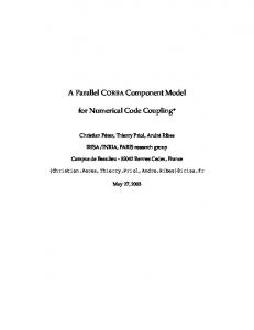
Composite Component Template Component Template Structure
Contract
Data Parameters
Data Constraints
Services
Data Security
Interface Types
Service Security
Frame
User Identity
Architecture Types
Reactivity
Connector Types
Time Constraints
Contract Composition
Structural Composition
Composition
Fig. 1. Composite Component Template
component are issues that we do not address in this paper. Ensuring the integrity of data communicated by a component to its client is part of correctness issue. Enforcing that only authorized clients request and receive services from a component is vital to ensure confidentiality. Authorization in the system is based on user identity [19,23]. A user represents an entity, may be human or system component to whom services are provided and on whose behalf services are requested. Security violations, which in our case is the unauthorized usage of system resources, will directly affect the availability, reliability, and safety of the system. From the above discussion it can be concluded that safety and security are essential prerequisites for ensuring availability and reliability. Therefore we conclude that the essential credentials for ensuring trustworthiness of RTRS are safety and security. This is the justification for focusing only on these two aspects in this paper. 2.3
Elements of a component model
This section is a brief introduction to the elements of a component model. Detailed formal definitions are presented in Section 3. Figure 1 shows a component template composed of a structure part and a contract part. The structure of a template is an abstract external black-box view, called frame, and its internal hierarchical structure, called architecture. The frame consists of the interface types, where each interface type is associated with a set of services. A service may be parameterized with data types. An architecture is a collection of connector types, an abstract view of the tie-ins between interface types. The contract part of the template states the properties required of the system for which the structure is a blue print. A component is an instance of a component template. Every component instantiated from a template has one instance of the structure part defined for the template. The frame of the component is a set of interfaces, where each interface belongs to exactly one interface type in the template frame. An architecture instance corresponding to a component frame is an instance of the architecture corresponding to the frame in the template, having as many 4
Alagar and Mohammad
instances of connector types as are required for linking the interfaces in the component. A component’s contract constrains the communication pattern at its interfaces and is faithful to the contract part in its template. A component frame can contain multiple interfaces of an interface type. This enables a RTRS component to interact in a similar way with several other components, receive/send many interactions at the same time, and perform simultaneous processing. Through contracts we can specify the requirements of timeliness, reactivity, safety, and security at different interfaces of the same type. At each interface of a component frame, stimuli and reactions can be regulated, restricted and filtered. Regulating reactions at an interface ensures timeliness, restricting reactions promotes safety, and filtering services at interfaces can protect the component from unauthorized use. By scrutinizing the nature of a stimulus and the response to it at an interface, a request for service can be either authenticated or denied. The data parameters carried by a response at an interface of the component frame can be validated both for integrity and confidentiality. Moreover, obligations associated with responses can be verified at frame interfaces. Due to space limitation we discuss only the structure and contract formal definitions in this paper. In [2] we discuss the behavior specification of a component, which can be generated automatically from the structure and contract specification.
3
Specifications of Trustworthy Components
In this section we discuss three issues. These are (1) basic definitions that lead to a formal definition, (2) a formal definition of un-timed components, and (3) a formal definition of RTRS components that exhibit safe and secure behavior. 3.1
Basic definitions
We use the template notation [21], although conceptually and semantically our definition of frame and architecture are different. •
A component requests/provides a set of services. We assume a finite non-empty set of services Σ, in which every service is either a stimulus or a response. A service cannot be both a stimulus and a response for a component.
•
An interface type is an enumerated type whose elements are services from Σ. An interface is an instance of an interface type, it inherits the services listed in the type definition. Two interface types P and Q are compatible if and only if for every service s : P there exists exactly one service s : Q such that s and s are complementary. That is, in designing component interaction both s and s will be assigned to occur simultaneously at component interfaces of interacting components. We define the predicate Compatible(P, Q) which is true if and only if P and Q are compatible.
•
A frame is a black-box with a finite (non-empty) set of interface types, such that no two pairs of interface types of the frame are compatible.
•
A Connector type is a tuple (L, M ), where L is a link specification and M is a communication style specification. The link specification L is a tuple (F1 , P, F2 , Q), where P is an interface type of frame F1 , Q is an interface type of frame F2 and (P, Q) are compatible interface types. This abstraction allows us to define composition of frames. 5
Alagar and Mohammad
We use the notation P @ F1 ⊞ Q @ F2 , instead of tuple notation, to introduce a connector type link. The communication style M specifies the type of communication used by the connector to deliver services. There are a number of common communication styles to choose from [24]: procedure call, message passing, remote procedure calls, etc. This paper focuses on the link specification only. •
A frame has an associated architecture, an abstract implementation of it. In general, more than one architecture may correspond to a frame as different implementation versions. If the specification of the architecture of a frame is given by a program implementation then the frame is primitive. A non-primitive component is a composite frame, which includes two or more frames. The architecture specification of a composite frame is a grey-box view of the frame. It includes the black-box definitions of the constituent frames and a specification of connectors used to compose them.
•
A template, also called component type, is a tuple CT = (F, A) where F is a frame and A is an architecture of frame F . We use the notation CTF and CTA to respectively denote the frame and architecture of the component type CT .
•
A component is an instance of a component type. A component instance C of type CT = (F, A) is the tuple C = (F ′ , A′ ), where F ′ , called component frame, has interfaces that are instances of interface types in the definition of F , and A′ , called the component architecture, has connectors that correspond to the connector types in A. We use the notation CF and CA to respectively denote the frame and architecture of the component C. In general, if C is an instance of CT then CF is an instance of CTF , and CA is an instance of CTA . The component frame CF can have one or more interfaces that are instances of an interface type of CTF . The aggregation of all interface instances in CF , hereafter called interfaces of the instantiated component C, provides a black-box view of the component C. If p, an interface of CF , is an instance of the interface type P of frame CTF , the interface p inherits all the services in the type definition of P . That is, in the component C services that are inherited by p are either requests (stimulus) received at p or provides sent out at p.
•
A connector is an instance of a connector type. It implements the communication style specified in the connector type. We use the symbol ⊲⊳ to denote the link part of a connector. As an example, a connector link of type P @ F1 ⊞ Q @ F2 is p @ f1 ⊲⊳ q @ f2 , if f1 is an instance of F1 , P is an interface type in F1 , p is an instance of P , f2 is an instance of F2 , Q is an interface type in F2 , and q is an instance of Q.
The template definition enables the dynamic configuration of components at instantiation time. This is because the frame definition consists only of interface types and the architecture definition consists only of connection types. When a component is instantiated, multiple instances of each interface type and connection types can be created and linked to create different versions of the frame and the architecture. Different notations are given to the type definitions of: frame(CTF ), interface(P ), architecture(CTA ), and connection link(P @ F1 ⊞ Q @ F2 ) than those given to the instances of those entities: CF , p, CA , and p @ f1 ⊲⊳ q @ f2 respectively. This enables the formal specification of dynamic configuration.
6
Alagar and Mohammad
3.2
Un-timed components - a formal definition
An un-timed component requests/provides services without being governed by time restrictions. In the rest of this section we simply refer to an un-timed component as component. Services are modeled as events occurring at the interfaces of a component frame. Therefore, every element of Σ is considered an actual event. A service request (stimulus) is an input event representing an information flow from outside the component to the inside. On the other hand, a service provision is an output event representing an information flow from inside the component to the outside. Input and output events are external events. Internal processing of services inside the component is done using internal events. Therefore, Σ is divided into a set of input events Σinput , a set of output events Σoutput , and a set of internal events Σinternal . Formally, Σ = Σinput ∪ Σoutput ∪ Σinternal and Σinput ∩ Σoutput ∩ Σinternal = ∅. Service requests and responses may include information carried by events. These information are modeled as data parameter values attached to events. We assume a finite set of data parameters Λ, in which every data parameter can be assigned to one or many events. A component should be specified as a black-box entity to enable designers to reuse it without knowledge of its internal structure [10]. From the basics explained in Section 3.1 it is clear that we need to formally specify a component type CT . Definition 3.1 Let CT be a primitive component type. The specification of frame CTF is a tuple < Π, Σ, Λ, Ξ, σ >, where Π is a finite non-empty set of interface-types such that ∀P ∈ Π, ∀Q ∈ Π • ¬Compatible(P, Q), Σ is a finite set of events, Λ is a finite set of data parameters, Ξ : Σ → PΛ is a function that associates with each event a set of data parameters, and σ : Π → PΣ is a function that associates a finite non-empty subset of external events to each interface-type such that ∀P, Q ∈ Π, σ(P ) ∩ σ(Q) = ∅. Definition 3.2 Let CT be a composite component type. The specification of CTF is the specification of its constituent frames, each specified as in Definition 3.1. Compatible interface types of the frames are used to connect the frames and define connector types. Other non-compatible interface types form the set of interface types of CTF . The specification of architecture type CTA is a collection of connector types, where each connector type link is of the form P @ F1 ⊞ Q @ F2 , where F1 and F2 are two frames in defining CTF and the interface type P of F1 is compatible with the interface type Q of F2 . Definition 3.3 A component frame CF is created from the template frame CTF by specifying for each interface type P in CTF the number of interfaces (#P ) of type P required in CF . If #P = n, we let CP = {p1 , . . . , pn } denote the interfaces created. A specification S of CF is < ΠI , Σ, Λ, Ξ, σ >, where ΠI = P ∈ CTF CP . The σ function is extended to interfaces: ∀p ∈ P • σ(p) = σ(P ). A component architecture CA from the template architecture CTA is created by defining n connectors in CA for each connector type in CTA if n interfaces have been created in CF corresponding to the interface type(s) in the connector type. Example 3.4 Let CTF be a composite frame whose constituent frames are F1 =< Π1 , Σ1 , Λ, Ξ1 , σ1 >, and F2 =< Π2 , Σ2 , Λ, Ξ2 , σ2 >, where Π1 = {X, Y }, Π2 = {Z, W }, Σ1 = {e1 , e2 , e3 }, Σ2 = {e1 , e2 , e3 }, Λ = ∅, Ξ1 (e1 ) = Ξ1 (e2 ) = Ξ1 (e3 ) = Ξ2 (e1 ) = Ξ2 (e2 ) = Ξ2 (e3 ) = ∅, σ1 (X) = {e1 }, σ1 (Y ) = {e2 , e3 }, σ2 (Z) = {e1 }, σ2 (W ) = {e2 , e3 }. Interface types X and Z are compatible, as well as interface types Y 7
Alagar and Mohammad
and W are compatible. An architecture type CTA for CTF is defined below: X @ F1 ⊞ Z @ F2 Y @ F1 ⊞ W @ F2 Example 3.5 Let x1 , x2 : X, y1 : Y , z1 : Z, and w1 , w2 : W . Let F1′ and F2′ be instances of F1 and F2 respectively. The specification of the composite component frame is given below: F1′ =< ΠI1 , Σ1 , Λ, Ξ1 , σ1 >, F2′ =< ΠI2 , Σ2 , Λ, Ξ2 , σ2 >, where ΠI1 = {x1 , x2 , y1 }, and ΠI2 = {z1 , w1 , w2 }, σ1 (x1 ) = σ1 (x2 ) = {e1 }, σ1 (y1 ) = {e2 , e3 }, σ2 (z1 ) = {e1 }, σ2 (w1 ) = σ2 (w2 ) = {e2 , e3 }. Two possible instance architectures CA1 and CA2 of CTA , are given below: CA1
CA2
x2 @ F1′ ⊲⊳ z1 @ F2′
x1 @ F1′ ⊲⊳ z1 @ F2′
y1 @ F1′ ⊲⊳ w1 @ F2′
y1 @ F1′ ⊲⊳ w2 @ F2′
the interfaces x1 and w2 are free.
the interfaces x2 and w1 are free.
Free interfaces can be used to connect the component to other components. By a component C we mean the pair (CF , CA ). The architecture CA is an abstract implementation of the component frame CF . The behavior of C is the implementation behavior of CA , and is observed at the interfaces of CF . We define the behavior at an interface p of CF as a set of sequences over σ(p). The behavior of component C is the arbitrary interleaving of sequences at the interfaces of CF . 3.3
Timed reactive components (TRC)- a formal definition
A reactive component is a component that maintains continuous interaction with its environment through stimulus and response (reaction). A stimulus is an input event and a response is either an output or an internal event. In a timed system, timing information is associated with event occurrences. A timed reactive component (TRC) is a reactive component whose responses are governed by constraints of the following two types: (1) time constraints, and (2) data parameter constraints. First, a response e can be constrained to happen, say at time te within a time bound [le , ue ). That is, le ≤ te < ue . Second, a response can be enabled or disabled using data parameter constraints. These constraints are logical expressions that evaluate to boolean values based on the values of data parameters carried by the stimulus. Hence, we extend the formal definition of the un-timed component frame to include reactivity and a finite set of constraints. Definition 3.6 The frame definition of a TRC is obtained by extending the frame definition of un-timed system with the parameters Θ, Γ, Ω as defined below: Θ : Σinput → Σoutput ∪ Σinternal is a total function that associates a set of responses to each stimulus, Γ is a finite set of timing constraints for the events in Σ, where each time constraint Γ(s, r) involves conjuncts of the form (t(r) − t(s)) ◦ n, where t(.) is the time function for event occurrences, s ∈ Σ is a stimulus, r ∈ Σ, r ∈ Θ(s) is a response to s, ◦ ∈ {}, and n : N, and 8
Alagar and Mohammad
Ω is a finite set of constraints for the data parameters associated with the events in Σ, where each data constraint of an event s ∈ Σ is a predicate defined over the values of the data parameters associated with s. If s has n number of responses in Θ(s) than there must be n number of mutually exclusive data constraints defined over the data parameters of s. This ensures that the responses of s are mutually exclusive. A TRC frame CTF is written as < Π, Σ, Λ, Ξ, σ, Θ, Γ, Ω >. Definition 3.7 For a TRC component C with frame CF =< ΠI , Σ, Λ, Ξ, σ, Θ, Γ, Ω > we define the behavior at an interface p as a set S(p) of timed sequences, where each sequence ω ∈ S(p) contains only stimulus and response events belonging to σ(p) ∪ Σinternal , and satisfies the following conditions (safety requirements): •
[S1] for every stimulus s in ω, s ∈ σ(p), there exists exactly one response r ∈ Θ(s). The stimulus s may occur at many different times in ω; let s[i] denote an occurrence of s in ω, then for every s[i] there exists exactly one response r[i] where r[i] ∈ Θ(s), i : N, i < number of events in ω. It is possible to have different responses for different occurrences of the same stimulus (based on data constraints in Ω),
•
[S2] t(r[i]) ≥ t(s[i]), where t(.) is the time function for event occurrences and r[i], s[i] denote an occurrence of s and r in ω. Also, t(s[i]) > t(s[j]) ∧ t(r[i]) > t(r[j]), i, j : N, i > j ∧ i, j < number of events in ω. This means that an event may occur at difference times in the timed sequence where always the time of the later occurrence is greater than the time of the former occurrence of the same event, [S3] for every stimulus s ∈ ω and response r ∈ Θ(s), t(r) conforms to Γ(s, r), and
• •
[S4] for every stimulus s ∈ ω and response r ∈ Θ(s), if there is a data constraint defined over the data parameters of s then the data constraint is satisfied. If there are many data constraints defined on the data parameters of s then one of them is satisfied.
Notice that [S1] assures predictability, [S2] and [S3] assure timeliness, and [S4] asserts that safety requirements are satisfied. Event names in the sequences of S(p) can be qualified by the name of the interface instance p, from which the event originated. Definition 3.8 The behavior of a reactive component is the arbitrary interleaving of the behaviors at the interfaces of the component. 3.4
Secure-TRC (STRC)- a formal definition
A TRC which has no security restriction will respond to every stimulus received by it. The introduction of security properties at the frame of a TRC will enrich its behavior by forcing (1) an analysis of the stimulus received before processing it internally, and (2) an analysis of the response before sending it. In order to enforce security analysis at the interfaces of a component, we use a security mechanism that unifies both access control and interface security models. Access control models restrict access to component services, and validates user requests of authorized users. We apply this restriction at the interfaces of components. The security mechanism defines: (1) user identities, (2) access control matrices, and (3) security access functions. First, in computer security [6] the identity of the entity executing a process is the basis for assigning and checking security access rights. We assume a list of all possible identities defined at the system level. In our discussion, the user identity, 9
Alagar and Mohammad
henceforth called user, is associated with the component at its instantiation time. All access control to system resources assume that the association is correct. Verifying the correctness of the identity and describing how it is associated to components falls outside the scope of this paper. Second, Ensuring security requires an explicit definition of an access control matrices that define the access level of users to both services (events) and information associated with services. Third, security access functions are used to check if the user of the component is authorized to request a service (send a stimulus) and/or receive a service (response) from the TRC. Also, it checks if the user is authorized to view the information carried by the response. If the user is denied access, the stimulus will be ignored. Also, if the user is not authorized to view a data parameter, the parameter will be filtered. Based on the stated security mechanism, the security property of a TRC can be defined in terms of event-security and data-security. Definition 3.9 An interface of a TRC is event-secure if (1) every stimulus event is received from a user who is authorized to trigger the stimulus, and (2) for every response event sent, the user receiving the response is authorized to view the response. An interface of a TRC is data-secure if (1) the TRC user has access rights for the data parameters in every stimulus sent by the user, and (2) for every response sent by the TRC, the user receiving the response has access rights for the data parameters in the response. Definition 3.10 A sequence of events at a component interface is secure if and only if it is event-secure and data-secure. A TRC is secure if and only if all event sequences at all its interfaces are secure. The frame specification of a STRC is defined by extending the frame specification of the TRC with security specifications. We assume that U denotes the set of users. For the sake of simplicity we assume AC = {grant, deny} is the set of access rights for events, and DA = {read, write} is the set of allowed actions on data. Definition 3.11 The frame specification CTF of a STRC is obtained by extending the tuple < Π, Σ, Λ, Ξ, σ, Θ, Γ, Ω > with functions Υ, Ψ, where Υ : U × Σ → AC is the event-security access function that assigns for every pair (user, event) an authorization which is either grant or deny, and Ψ : U × Λ → P DA is a data-security access function that assigns for every pair (user, data) an authorization which is a subset of DA. If Ψ(u, d) = ∅ user u is denied access to data d. A STRC component is thus the tuple < Π, Σ, Λ, Ξ, σ, Θ, Γ, Ω, Υ, Ψ >. In a STRC, we require the behavior S(p) at every interface p of CF to satisfy the following conditions (security requirements): for every sequence ω ∈ S(p), for every stimulus s in ω, s ∈ σ(p) let u denote the user associated with the component injecting s, let u′ denotes the user associated with the component which will receive the response, u, u′ ∈ U : • •
[C1] Υ(u, s) = grant and Υ(u′ , Θ(s)) = grant, and [C2] for every data parameter d ∈ Ξ(s) and d′ ∈ Ξ(Θ(s)), Ψ(u, d) = {read, write} and Ψ(u′ , d′ ) = {read}.
Definition 3.12 A trustworthy component (TTRC) is a STRC whose behavior satisfies the conditions [S1], [S2], [S3], [S4], [C1], [C2]. 10
Alagar and Mohammad
3.5
Specification of security properties
In the literature, safety and security properties are formally specified and verified using different methods. This is due to the common consensus that while safety properties are defined as sets of “safe” sequences, security properties cannot be expressed as sets of sequences[18,27,16]. It is known [1] that safety properties can be preserved in a composition, however some security properties are not preserved by any composition [17]. This implies that different formal methods have to be used for the specification and verification of security independent of safety. We argue that event-security and data-security properties suggested by this paper can be expressed as sets of sequences. Hence, these security properties can be expressed in any mathematical logic in which safety properties are expressed. Therefore, a unified method can be used for the formal specification and verification of safety and security requirements. Definition 3.13 Let S(p) be the set of sequences occurring at an interface p of CF . Each sequence ω ∈ S(p) consists of stimuli and responses satisfying the conditions S[1], S[2], S[3], S[4] in Definition 3.7. Let #ω denote the number of events in a sequence ω, e[i] denote the event at the index i of sequence ω, u denote the identity of the user injecting the stimulus e[i], Θ(e[i]) denote the response of e[i], and u′ denote the identity of the user who will receive the response. The event security property at the interface p is ∀ω ∈ S, 1 ≤ i ≤ #ω • (Υ(u, e[i]) = grant) ∧ (Υ(u′ , Θ(e[i])) = grant) The data security property at the interface p is ∀ω ∈ S, 1 ≤ i ≤ #ω • ∀d ∈ Ξ(e[i]), ∀d′ ∈ Ξ(Θ(e[i])) • (Ψ(u, d) = {read, write}) ∧(Ψ(u′ , d′ ) = {read})
4
Composition of Trustworthy Components
Informally, composition means “gluing together” two or more components to form a new component. A given set of components can be composed in different ways to achieve different results. However, the challenging aspect is to develop a set of rules for a stated requirements of trustworthiness to be preserved in a composition. It should be possible to reason about the properties of the composite component relative to the properties of the constituent components. In this respect composition of components is different from component integration [10]. In this section we propose a composition rule that composes both the structure part and the contract part of components. For example, composing two components C1 and C2 results in a new composite components C such that: (1) the structure part of C results from gluing the compatible interfaces of C1 and C2 , and (2) the contract part of C results from composing the contracts of C1 and C2 . For the composition to be trustworthy, it should preserve the requirements of trustworthiness ([S1], [S2], [S3], [S4], [C1], [C2]). 4.1
Composition of TTRCs
In this section we define the composition of templates CT1 and CT2 . 11
Alagar and Mohammad
Definition 4.1 Let CT1F =< Π1 , Σ1 , Λ1 , Ξ1 , σ1 , Θ1 , Γ1 , Ω1 , Υ1 , Ψ1 > and CT2F =< Π2 , Σ2 , Λ2 , Ξ2 , σ2 , Θ2 , Γ2 , Ω2 , Υ2 , Ψ2 >, their corresponding architectures CT1A and CT2A are hidden. The composition rule defines a unique CTF which can have many architectures CTA . The composition CTF =< Π, Σ, D, Ξ, σ, Θ, Γ, Ω, Υ, Ψ > is given below: Π = {P |(P ∈ Π1 ∧ ∄Q ∈ Π2 • Compatible(P, Q)) ∨ (P ∈ Π2 ∧ ∄Q ∈ Π1 • Compatible(P, Q))} Σ = Σ1 ∪ Σ2 Λ = Λ1 ∪ Λ2 ∀e ∈ Σ, Ξ(e) = {Ξ1 (e) | e ∈ Σ1 } ∪ {Ξ2 (e) | e ∈ Σ2 } ∀P ∈ Π, σ(P ) = {σ1 (P ) | P ∈ Π1 } ∪ {σ2 (P ) | P ∈ Π2 } ∀e ∈ Σ, Θ(e) = {Θ1 (e) | e ∈ Σ1 } ∪ {Θ2 (e) | e ∈ Σ2 } Γ = Γ1 ∪ Γ2 . Notice that we want to retain the constraints at the interfaces that are no more ‘visible’ in order that we can reason about grey-box behavior. Ω = Ω1 ∪ Ω2 if e ∈ Σ1 ∩ Σ2 ∧ Υ1 (u, e) = Υ2 (u, e) = grant; grant, deny, if e ∈ Σ1 ∩ Σ2 ∧ Υ1 (u, e) = deny ∨ Υ2 (u, e) = deny; ∀e ∈ Σ, ∀u ∈ U, Υ(u, e) = / Σ2 ; Υ1 (u, e), if e ∈ Σ1 ∧ e ∈ Υ (u, e), if e ∈ Σ ∧ e ∈ /Σ 2
2
1
Ψ1 (u, d) ∩ Ψ2 (u, d), if d ∈ Λ1 ∩ Λ2 ; ∀e ∈ Σ, ∀d ∈ Ξ(e), ∀u ∈ U, Ψ(u, d) = Ψ1 (u, d), if d ∈ Λ1 ∧ d ∈ / Λ2 ; Ψ2 (u, d), if d ∈ Λ2 ∧ d ∈ / Λ1
∀P ∈ Π1 , ∀Q ∈ Π2 , if Compatible(P, Q) then there exists a connector type P @ CT1F ⊞ Q @ CT2F in CT . There could be many architecture types for CTF because not all the interfaces in the resulting connector types should be linked. Also, different component instances can have a different number of connector and interface instances which enables the component to have different possible dynamic architectures. We assert that the composition rule stated in Definition 4.1 preserves the requirements of safety and security ([S1], [S2], [S3], [S4], [C1], [C2]). Theorem 4.2 The composition of two TTRCs results in a TTRC. The proof is provided in the Appendix.
5
Related Work
We compare our model with the state of the art component model SOFA 2.0 [7,14,8]. A comparison between SOFA 2.0 and the other component models can be found in [13]. SOFA 2.0 is a hierarchical component model that inherits structure from its ancestor SOFA [21]. The main features of SOFA 2.0 include: (1) a meta-model based design of components, (2) support for dynamic reconfiguration of architectures using predefined patterns that allow adding/removing components and connecting to external services, (3) support for different communication styles by defining connectors as first class components, (4) defining the control part of components using micro-components, and (5) providing 12
Alagar and Mohammad
design time and runtime environments for the development and deployment of component based systems. In this paper, we compare the relevant formal and structural aspects of our model with their correspondents in SOFA 2.0. Our work differs from SOFA 2.0 fundamentally in that our model is supporting RTRS. The introduction of time brings sophistication to system design and composition. Also, our model provides formal foundation for the specification and verification of safety and security properties [2] which is not supported by SOFA 2.0. Furthermore, in SOFA, the frame is defined as an aggregation of interfaces, whereas in our model the frame is an aggregation of interface types. Also, the architecture of composite components in SOFA defines connectors while in our model it defines connector types. This allows, in our model, a dynamic configuration of the component’s black-box and internal structure at deployment time benefiting from the available information. This is because it is possible, in our model, to create multiple instances of each interface type and instantiate connectors to each of them at the time of instantiating an architecture from the design time architecture type selected for a frame. However, SOFA 2.0 defines a static deployment model and allows reconfiguration later. The reconfiguration of components in SOFA 2.0 is not suitable for trustworthy RTRS because (1) removing components affects the availability of services which violates an important requirement of RTRS, (2) adding new components may introduce new security threats. In SOFA 2.0, connectors define end points that can be connected to any interface; however, in our model we specify interface types in the link of the connector type. This enables us to enforce and check compatibility between connected interfaces.
6
Conclusion
In this paper, we have presented one part of our ongoing research work on a formal approach to component modeling for the development of trustworthy RTRS. We have presented a formal foundation for defining and composing hierarchical structure and contract for trustworty components. We pointed out that safety and security are the two essential credentials that can assure high degree of trustworthiness. We have shown that using CBD it is possible to formally specify trustworthy components and compose them. This approach leads us to a unified method for the verification of trust using model checking, which has been shown to be a promising method for the verification of safety properties for RTRS. Currently, we are working on the automatic generation of the behavior protocol for trustworthy components from its structure and contract views. We are investigating a model checking approach that first translates the component model to UPPAAL language and uses the model checker in UPPAAL toolset to verify trustworthiness credentials [2].
7
Appendix
In this section we provide proof for Theorem 4.2. Proof. Let C1 and C2 , instances of CT1 and CT2 respectively, be two trustworthy components. Their behavior satisfy the properties [S1],[S2],[S3],[S4],[C1], and [C2]. Let C be an instance of CTF , the composition of CT1F and CT2F according to Definition 4.1. Let S1 and S2 be behaviors representing the set of all possible observed sequences of C1 and C2 respectively, S be the behavior of the composite component C representing the set of all possible observed sequences of C, S(p) be the behavior at an interface p instantiated 13
Alagar and Mohammad
from interface type P ∈ Π in CF . The proof procedure consists of 3 steps: (I) a proof that the behavior of C satisfies the properties [S1],[S2],[S3], and [S4], (II) a proof that if C1 satisfies safety property τ1 and C2 satisfies safety property τ2 then C satisfies both τ1 and τ2 i.e. the composition preserves safety properties, and (III) a proof that the behavior of C satisfies [C1] and [C2] i.e. the composition preserves event security and data security. We use the following properties in the proof. (Prop.1) From Definition 3.1 every event is associated with only one interface type: ∀P, Q ∈ Π, σ(P ) ∩ σ(q) = ∅, (Prop.2) from Definition 3.2 every interface type in the composite frame belongs only to one frame definition CT1F or CT2F : ∀P ∈ Π • (P ∈ Π1 ∨ P ∈ Π2 ) ∧ (P ∈ / Π1 ∩ Π2 ), (Prop.3) from Definition 3.1 there are no two interface types that are compatible in the composite frame definition CF : ∄Q ∈ Π, Compatible(P, Q). Preserving properties [S1],[S2],[S3], and [S4]: from Definition 3.8, S is constructed from the arbitrary interleaving of the behaviors at the interfaces of CF . From Prop.2, every interface p in CF is either an interface at C1F or at C2F . Since the behaviors S1 (p) or S2 (p) for every interface p in C1 and C2 satisfies [S1],[S2],[S3], and [S4] then the behavior S(p) of every interface p at CF satisfies those properties. Preserving Safety: Let τ1 and τ2 be two safety properties, R1 and R2 be the set of all sequences which satisfy τ1 and τ2 respectively. That is, sequences of C1 satisfy τ1 and sequences of C2 satisfy τ2 . Therefore, S1 ⊆ R1 ∧ S2 ⊆ R2 . From Prop.1, Prop.2, and Prop.3 we have ∀p : P, P ∈ Π, ∀ω ∈ S(p), ω ∈ S1 (p) ∨ ω ∈ S2 (p). This means that ∀ω ∈ S(p), ω ∈ R1 ∨ ω ∈ R2 . Hence, ∀ω ∈ S(p), ω ∈ R1 ∪ R2 . Thus, S(p) ⊆ R1 ∪ R2 . Therefore, S ⊆ R1 ∪ R2 , the composition satisfies both τ1 and τ2 . This shows that the composition preserves safety properties. Preserving event security [C1]: Let ω ∈ S, u, u′ ∈ U be users and u[i], u′ [i] denote the user stimulating the event at index i of ω and the user receiving the response respectively. From Prop.1, Prop.2, and Prop.3: ∀P ∈ Π, ∀e ∈ σ(P ), (e ∈ Σ1 ∨ e ∈ Σ2 ) ∧ (e ∈ / Σ1 ∪ Σ2 ). Therefore,∀ω ∈ S, ∀i ∈ N • 1 ≤ i ≤ #ω • (Υ(u[i], e[i]) = Υ1 (e, u), Υ(u[i]′ , Θ(e[i])) = Υ1 (u[i]′ , Θ(e[i])) ∧ e ∈ Σ1 ) ∨ (Υ(u[i], e[i]) = Υ2 (u[i], e[i]), Υ(u[i]′ , Θ(e[i])) = Υ2 (u[i]′ , Θ(e[i])) ∧ e ∈ Σ2 ). Since ∀ω1 ∈ S1 , ∀i ∈ N • 1 ≤ i ≤ #ω1 • Υ1 (e[i], u[i]) = grant ∧ Υ1 (u′ [i], Θ(e[i])) = grant and ∀ω2 ∈ S2 , ∀i ∈ N • 1 ≤ i ≤ #ω2 • Υ2 (e[i], u[i]) = grant ∧ Υ2 (u′ [i], Θ(e[i])) = grant. Thus,∀ω ∈ S, ∀i ∈ N • 1 ≤ i ≤ #ω • Υ(e[i], u[i]) = grant ∧ Υ(u′ [i], Θ(e[i])) = grant. Therefore, the composition preserves the event-security property. Preserving data security [C2]: From Prop.1, Prop.2, and Prop.3: ∀P ∈ Π, ∀e ∈ σ(P ), (Ξ(e) ⊆ Λ1 , Ξ(Θ(e)) ⊆ Λ1 ∨ Ξ(e) ⊆ Λ2 , Ξ(Θ(e)) ⊆ Λ2 ) ∧ (∀d ∈ Ξ(e), ∀d′ ∈ / Λ1 ∩ Λ2 ). Thus, ∀ω ∈ S, ∀i ∈ N • 1 ≤ i ≤ #ω, ∀d ∈ Ξ(Θ(e)) • d, d′ ∈ ′ Ξ(e[i]), ∀d ∈ Ξ(Θ(e[i])) • ( Ψ(u[i], d) = Ψ1 (u, d), Ψ(u′ [i], d′ ) = Ψ1 (u′ [i], d′ ) ∧ e ∈ Σ1 ) ∨ ( Ψ(u[i], d) = Ψ2 (u[i], d), Ψ(u[i]′ , d′ ) = Ψ2 (u′ [i], d′ ) ∧ e ∈ Σ2 ). Since ∀ω1 ∈ S1 , ∀i ∈ N • 1 ≤ i ≤ #ω1 , ∀d ∈ Ξ(e[i]), ∀d′ ∈ Ξ(Θ(e[i])) • Ψ1 (u[i], d) = {read, write} ∧ Ψ1 (u′ [i], d′ ) = {read} and ∀ω2 ∈ S2 , ∀i ∈ N • 1 ≤ i ≤ #ω2 • Ψ2 (u[i], d) = {read, write} ∧ Ψ2 (u′ [i], d′ ) = {read}. Hence,∀ω ∈ S, ∀i ∈ N • 1 ≤ i ≤ #ω • Ψ(u[i], d) = {read, write} ∧ Ψ(u′ [i], d′ ) = {read}. Therefore, the composition preserves the data security property. 2
14
Alagar and Mohammad
References [1] Abadi, M. and L. Lamport, Composing specifications, ACM TOPLAS 15 (1993), pp. 73–132. [2] Alagar, V. and M. Mohammad, Specification and verification of trustworthy component-based real-time reactive systems, in: Proceedings of SAVCBS’07, Dubrovnik, Croatia, 2007. [3] Avizienis, A., J.-C. Laprie and B. Randell, Fundamental concepts of dependability, Research report n01145, laas-cnrs (2001). [4] Barros, T., L. Henrio and E. Madeliane, Behavioural models for hierarchical components, in: Proceedings of the 12th International SPIN Workshop Model Checking Software (2005), pp. 154–168. [5] Bellegarde, F., J. Julliand, H. Mountassir and E. Oudot, On the contribution of a tau-simulation in the incremental modeling of timed systems, in: Proceedings of FACS’05, Macao, 2005, pp. 117–132. [6] Bishop, M., “Computer Security: Art and Science,” Addison Wesley, 2003 pp. 353–360. [7] Bures, T., P. Hnetynka and F. Plasil, Sofa 2.0: Balancing advanced features in a hierarchical component model, in: Proceedings of SERA’6, Seattle, Washington, USA, 2006, pp. 40–48. [8] Bures, T., P. Hnetynka, F. Plasil, J. Klesnil, O. Kmoch, T. Kohan and P. Kotrc, Runtime support for advanced component concepts, in: Proceedings of SERA’07, Busan, Korea, 2007. [9] Carlson, J., J. H˚akansson and P. Pettersson, Saveccm: An analysable component model for real-time systems, in: Proceedings of FACS’05, Macao, 2005, pp. 127–140. [10] Crnkovic, I. and M. Larsson, editors, “building reliable component-based Software Systems,” Artech House Publishers, 2002. [11] Gu, Z. and K. G. Shin, Model-checking of component-based event-driven real-time embedded software, in: Proceedings of IEEE ISORC’05, Washington, DC, USA, 2005, pp. 410–417. [12] Guerrouat, A. and H. Richter, A component-based specification approach for embedded systems using fdts, SIGSOFT Softw. Eng. Notes 31 (2006), pp. 91–95. [13] Hnetynka, P. and T. Bures, Advanced features of hierarchical component models, in: Proceedings of ISIM’07, Hradec nad Moravici, Czech Republic, 2007, pp. 3–10. [14] Hnetynka, P. and F. Plasil, Dynamic reconfiguration and access to services in hierarchical component models, in: Proceedings of CBSE’06, Vsters, Sweden, 2006, pp. 352–359. [15] Hung, D. V. and B. V. Anh, Model checking real-time component based systems with blackbox testing, in: Proceedings of IEEE RTCSA’05, Washington, DC, USA, 2005, pp. 76–79. [16] Mantel, H., On the composition of secure systems, in: Proceedings of the IEEE Symposium on Security and Privacy, Berkeley, California, USA, 2002, pp. 88–101. [17] McCullough, D., Noninterference and the composability of security properties, in: Proceedings of the IEEE Symposium on Security and Privacy, Oakland, California, USA, 1988, pp. 177–186. [18] McLean, J., A general theory of composition for a class of “possibilistic” properties, IEEE Trans. on Software Engineering 22 (1996), pp. 53–67. [19] Mundie, C., P. de Vries, P. Haynes and M. Corwine, Trustworthy computing, Microsoft White Paper (2002). [20] Neumann, P. G., Achieving principled assuredly trustworthy composable systems and networks., in: Proceedings of DISCEX’03, Washington, DC, USA, 2003, pp. 182–187. [21] Plasil, F. and S. Visnovsky, Behavior protocols for software components, IEEE Trans on Software Engineering 28 (2002), pp. 1056–1076. [22] Roshandel, R. and N. Medvidovic, Modeling multiple aspects of software components, in: Proceedings of SAVCBS’03, Helsinki, Finland, 2003, pp. 88–91. [23] Schneider, F. B., S. M. Bellovin and A. S. Inouye, Building trustworthy systems: Lessons from the ptn and internet, IEEE Internet Computing 3 (1999), pp. 64–72. [24] Show, M. and D. Garlan, “Software Architecture: Perspectives on an Emerging Discipline,” Prentice Hall Publishing, 1996. [25] Sommerville, I., “Software Engineering,” Addison Wesley, 2004, 6th edition. [26] Szyperski, C., “Component Software - Beyond Object-Oriented Programming Second Edition,” Addison-Wesley / ACM Press, 2002. [27] Zakinthinos, A., “On the composition of security properties,” Phd thesis, University of Toronto (1996).
15