Abstract- A computational vision approach is presented for the estimation of 2-D translation, rotation, and scale from two partially overlapping images.
IEEE TRANSACTIONS ON IMAGE PROCESSING,
311
VOL. 2, NO. 3, JULY 1993
A Computational Vision Approach to Image Registration Qinfen Zheng, Member, IEEE, and Rama Chellappa, Fellow, IEEE
Abstract- A computational vision approach is presented for the estimation of 2-D translation, rotation, and scale from two partially overlapping images. The approach results in a fast method that produces good results even when large rotation and translation have occurred between the two frames and the images are devoid of significant features. An illuminant direction estimation method is first used to obtain an initial estimate of camera rotation. A small number of feature points are then located based on a Gabor wavelet model for detecting local curvature discontinuities. An initial estimate of scale and translation is obtained by pairwise matching of the feature points detected from both frames. Finally, hierarchical feature matching is performed to obtain an accurate estimate of translation, rotation and scale. A method for error analysis on matching results is also presented. Experiments with synthetic and real images show that this algorithm yields accurate results when the scale of the images differs by up to lo%, the overlap between the two frames is as small as 23%, and the camera rotation between the two frames is significant. Experimental results on several Mojave desert images acquired from a balloon are presented. Applications of the method to texture and stereo image registration, and satellite image mosaicking are presented.
I. INTRODUCTION
A
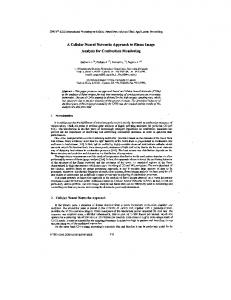
utomatic image registration is an important problem for steropsis, multiplatform remote sensing, motion estimation, moving object detection, etc. Traditional solutions to this problem [l], [4], [9], [lo], [ l l ] , [16] are unreliable when the rotation of the camera and scale change between the two frames are significant. Registration becomes even more difficult if the images are devoid of significant features and/or the overlap between the two frames is small. In the Mars '94 project we have such a challenging problem. One of the goals of the Mars '94 project is to measure the 3-D wind velocity on Mars. It is proposed to use a downlooking camera attached to a balloon to measure the motion of the balloon and hence determine the wind velocity. Fig. 1 schematically illustrates this project; the two successive images are taken at times tl and t 2 . Balloon motion can be determined by measuring the translation, rotation and scale changes between the two images. Due to technical constraints, only two frames will be available for each location, and the rotation and translation Manuscript received June 16, 1992; revised November 4, 1992. This work was supported in part by the Advanced Research Projects Agency under ARPA Order Number 8978, and in part by the U.S. Army Engineer Topographic Laboratories under contract DACA 76-92-C-0024. The associate editor coordinating the review of this paper and approving it for publication was Dr. Michael Unser. R. Chellapa is with the Department of Electrical Engineering and Q. Zheng is with the Center for Automation Research, Univerisity of Maryland, College Park, MD 20742-3275. IEEE Log Number 9208874.
Fig. 1 .
Geometry of a balloon imagery. Images are taken by a downlooking camera at time t l and t z .
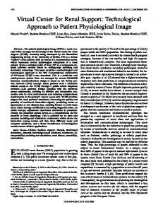
between the images could be significant. Also, there is a scale change due to the vertical motion of the balloon. A simple and robust registration algorithm is required for on-board motion estimation. In this paper, we present a computational vision approach to the estimation of 2-D translation, rotation, and scale from two partially overlapping images. Fig. 2 shows the block
1057-7149/93$03.00 0 1993 IEEE
312
IEEE TRANSACTIONS ON IMAGE PROCESSING, VOL. 2, NO. 3, JULY 1993
Azimuth Estimation Azimuth Estimation
by pairwise matching between the neighbors of feature points detected in both frames. In experiments with several desert balloon images acquired by JPL, our algorithm worked for all the cases tested. A consistency test based on forward and backward motion estimation showed that the estimates are quite accurate, with the discrepancies between forward and backward estimates of rotation, translation and scale being less than 0.13", 0.7 pixel, and 4.2 x lop3, respectively. We further applied our method to stereo pair and texture images registration, and satellite image mosaicking. The experiments are quite successful. The organization of the paper is as follows: Section I1 formulates the balloon motion estimation as an image registration problem; Section I11 discusses the basic steps used in our matching algorithm: first the illuminant azimuth estimator is introduced; then the Gabor wavelet model based feature extraction method is presented; and finally, issues of image transformation, matching criterion, scale estimation, and translation estimation are addressed. Section IV presents the matching algorithm. Section V-A presents experimental results on Mojave desert images taken from a balloon. Applications to texture image matching, stereo image matching, and satellite image mosaicking are presented in Section V-B-V-D. The work is summarized in Section VI.
h Initial Matching
f i I Affine Transform
I
Fig. 2.
Block diagram of image registration algorithm.
diagram of our motion estimation algorithm. A feature of our approach is that the camera rotation is estimated and compensated at the very beginning of the registering process. The illumination on the Martian surface is from the sun and is constant during the time the image pair is taken. By estimating the illuminant direction in each frame, we can compensate the rotation between the two frames and simplify the matching process. To estimate the illuminant azimuth, we use a local voting estimator in which the surface around each pixel is approximated by a local spherical patch and a local estimate is computed by a minimum mean square method. The global estimate of the illuminant azimuth is computed as the arc tangent of the ensemble average of the normalized local estimates. For image matching, since the common area between the two frames can be much smaller than the image field, and in addition, there is scaling between the two frames, spectrum analysis-based correlation and matching would be unreliable. In this work, we use a feature-based matching technique. First, we extract a small number of feature points based on a Gabor wavelet model for detecting local curvature discontinuity [13]. In doing this we compute a local energy measure defined as interaction of Gabor wavelet transforms of different scales, and taking the local maxima of the resulting energy map to be the feature points. The effect of local inhibition of nearby feature points is also considered. A coarse-to-fine correlation matching is performed to obtain an accurate camera motion estimate. In doing this, since no prior knowledge about the translation is available, an initial estimate of scale and translation is obtained
11. BALLOONMOTIONESTIMATION Let ( x t , y t , z t ) be the 3-D coordinates and (X2,Y,) be the image frame coordinates, both measured in the camera coordinates at time t,, for i = 1,2. The relationship between the two camera coordinates can be approximated by
(i;)
cos0 sin0 = (-T.5 co;o
;) (i;) + (;;)
0
(1)
where 0 is the camera rotation angle, (Ax, Ay, Az) is the displacement of the camera in the world coordinate system. Assume the focal length of the camera is f , under the central projection equations
we have X2=f-
='
x2 22
x1 cos0
+ y1 sin0 + Ax z~+Az
r-
313
ZHENG AND CHELLAPPA: A COMPUTATIONAL VISION APPROACH TO IMAGE REGISTRATION
where s is the scaling factor and (AX2, AY2) is the translation measured in the image coordinate system of frame t 2 :
(7)
and 6x1.SUI. 6 x 2 , and SY2 are the coordinate differences of any two points measured in image frames tl and t 2 , respectively. With AX2, AY,, 8 . and s determined, the balloon motion 77 = (Ax, Ay, Az) can be easily determined if the height of the balloon is available' using
Ax = -752. AX2 = S A X 2 f fs
AZ=z2-z1=(1-S)Z2=
(9)
surface normal and the direction toward the light source. L' = (cosrsiny,sin-rsiny,cosy) is the unit vector for the illuminant direction, where T , is 5alled the azimuth of the illuminant, is the angle between L and _the x-y plane. y, the slant angle, is the angle between L and the positive x axis ($ - y is the elevation of the illuminant). N = (N,, Ny, N , ) = (cos a sin p, sin a sin p, cos p) is the surface normal at position ( x , y , z ( x , y ) ) , with a = a ( z , y ) and ,/3 = p(x,y) the azimuth and slant angles of the surface normal at (x,y, ~ ( xy)). , g o is the bias brightness, depending on background illumination, digitizer calibration, and so on. With the Lambertian image model, the illuminant azimuth T can be estimated from the image intensity. Several algorithms [3], [8], [12], [14], [15], [19] are available for estimation of illuminant direction.* In this paper we use the local voting azimuth estimator introduced in [19]. Let us assume that for any point (xo,yo, z(xo,yo)), its neighbors can be locally approximated by a spherical patch:
x = a(xo,yo)+ r ( x o , y 0 ) s i n P c o s a
{
y = b(xo,yo)+r(xo,yo)sin~sina 75 = c(x0,yo) + ~ ( x o , Y o ) C O S P
(13)
where ( a ( x o yo), , b(xo,yo), c ( x o ,yo)) is the center of the sphere, ~ ( x ,yo) , is the radius of the ~ p h e r eand , ~ a and /? are the azimuth and slant angles of the surface normal. From (13) we obtain the following relations: x-a -= sin ,D cos a (14) r
(11) = sinpsina
(15)
111. BASIC STEPS Before discussing the algorithm, some definitions and basic steps are addressed. A. Initial Estimation of Camera Rotation
As shown in Fig. 2, the initial estimate of camera rotation is computed as the difference between the illuminant azimuth angles estimated from the two frames. To estimate the illuminant direction from an image we first need a model relating image intensity to illuminant source. In computer vision research, one of the most commonly used image formation models is the Lambertian model [5], [7]. For the balloon imaging scenario depicted in Fig. 1, the Lambertian model can be written as
= ~ [ C O S ( C U- 7 )sin p sin y
+ cos p cos y]+
-> I
-7 5 5 5 5 12 - 5 5 12
AS
\
0 9801 1019; 0 9849 1012G 0 9983 10059
(c) and (d) of Figs. 4-6 the transformation on (a) is performed by using the estimated motion parameters. The initial rotation estimate 8, and the final motion parameter estimates for the balloon images shown in Figs. 4-6 are listed in Table I. The continuity in the mosaic images and the patterns in the difference images show that the estimates are correct.
18 -1 9 1 G -1 T 43 G -13 7
5 G 2 4 G -1G19 112 -143 185 -191 231
1112 3
-24 6 -121 0 120 5
49 -1G-i 0
Further quantitative error analysis can be performed by checking the consistency between forward and backward motion estimates. For image pair f l ( X 1 , Y l ) and f2(X2,Y2), assume that the estimated parameters of the motion from fl(X1, Yl) to f2(X2,Y2) are SI, 6'1, AX,,and AY,,and the estimated Y2) to fl(X1,Yl) are parameters of the motion from fz(X2,
320
lEEE TRANSACTIONS ON IMAGE PROCESSING, VOL. 2, NO. 3, JULY 1993
TABLE I1 DIFFERENCES BETWEENFORWARD AND BACKWARD MOTIONESTIMATES
B02G B03G B140
BO29 BO38 B143
0 5331 2 751; 11131
3 53 190 1 2 27
0 171 -0 2G4 0 005
0 171 0 457 0 577
0 2G8 0 222 -0 518
0 074 0 053 -0 010
(c) (4 Fig. 7. Motion estimation for synthetic motion of the camera. (a) B036. (b) Transformed B036; (c) Mosaicking of (a) and (b). (d) Difference between BO36 and transformed B036. The transform parameters from (a) to (b) are .s = 0.9. 0 = 90'. AA\- = 50. and A l p = 50. The estimated parameters are .> = 0.901, H = S9.So. AAY = 49.9. and A l r = 50.0. Mosaicking is done after transforming (a) by the estimated motion parameters.
Combining (59) and (60) leads to
32 1
ZHENG AND CHELLAPPA: A COMPUTATIONAL VISION APPROACH TO IMAGE REGISTRATION
(c)
(dl
Fig. 8. Registration of wool pictures, (a) Wool-00. (b) Wool-30. (c) Mosaicking of Wool-00 and Wool-30. (d) Difference between the transformed Wool-00 and Wool-30. The estimated camera motion from Wool-00 to Wool-30 is .5 = 1.000. 0 = -30.2O. A X = 0.6. and AIr = 11.3. The zero of difference is shifted to 128.
cisb = $71(cos &AX2
O1
sin O1
s:)
) (E:) +(
(62) The differences between the forward and backward estimates of (s.0. AX. A Y ) can be defined as
+ sin 0lAY2) + AX1
= sl(-sin01AX2 +cos01AY2) + A Y , .
(67) (68)
Table I1 lists the results of the consistency tests on the forward and backward estimates. As shown in Table 11, for the images tested, the differences between the forward and backward estimates are bounded by7
< 4.2 x < 0.13' E A < 0.7 pixel. &e
elsf
= s2((;osQ2AX1 + sill (j2AY1) + AX2
€AI>
= S 2 ( - sin 02Ax1
+
COS
:!2Ay1)
+ AY,
(65) (66)
'The error bounds are obtained based on results of all tested balloon images, although only a few typical experimental results are given in this paper due to space limitation. Results on other experiments are reported in [IS].
IEEE TRANSACTIONS ON IMAGE PROCESSING, VOL. 2, NO. 3, JULY 1993
(c) Fig. 9. Registration of two robot arm images (first and seventh frames of a robot arm image sequence) (a) First frame. (b) Seventh frame. (c) Difference between the first and seventh frames, In (c) the first frame is first transformed using the estimated motion parameters: .z = 1.007. H = 21.S0. A X = -1.4. and 1 1 - = -31.6.
For experiments on image pair BO36 and B038, there are relative large errors in the difference image shown in Fig. 5 and the discrepancy between the forward and backward motion estimates is larger than in the other cases. This may be due to the balloon motion being over a mountain ridge leading to large elevation changes and errors in the orthogonal projection approximation. In Fig. 7, we test the algorithm on asynthetic motion of the camera. Fig. 7(a) is the central 256 x 256 section of B036. Fig. 7(b) is obtained by first transforming the image BO36 using parameters s = 0.9, 6' = go', A X = 50, and AY = 50 and retaining the central 256 x 256 portion. The estimated parameters of motion for Fig. 7(a)-Fig. 7(b) are s = 0.901. 6' = 89.8'. AX = 49.9. and AY = 50.0. The mosaic and difference of Figs. 7(a) and 7(b) are shown
in Figs. 7(c) and 7(d), respectively. The differences between the forward and backward motion estimates are E , = 2.2 x 10⁻³. Fti = 0.020, = -0.04, tAri = -0.09, = -0.17. and = -0.09. The errors in the motion parameter = 0.1 estimates are E , = 1.38 x 1 v 3 , € 0 = 0.19'. pixel, and = 0.0 pixel. B. Texture Image Registration Registration of texture images is a difficult problem in image processing. We have tested our algorithm on images of grass, leather, pigskin, sand, wood, and wool. In these experiments, the input images are 512 x 512, obtained by digitizing photographs [ 2 ] , [17] and their rotated version. The
323
ZHENG AND CHELLAPPA. A COMPUTATIONAL VISION APPROACH TO IMAGE REGISTRATION
(c) Fig. 10. Registration of two chemical plant images (the first and the last frames of the close viewed chemical plant image sequence). (a) The first frame. ( b ) The 32nd frame. (c) Difference between the first and 32nd frames. In (c) the first frame is first transformed using the estimated motion parameters: s = 1.OG3. H = 0 . 2 " . A X = -0.8. and A17 = -2S.G.
angles of rotation are about 30" as measured by a goniometer. Thus the transformation between the texture image pairs is expected to have a rotation of about 30", a scale close to 1, and a small amount of translation. In the implementation of our registration algorithm, we used the same set of parameters as for the experiments of balloon image registration, i.e., the image size for the lowest resolution layer is 128 x 128 and the window parameters of the matching window and the search space are set to UI,, = 8 and w, = 3 respectively. A typical result is presented in Fig. 8. In Fig. 8, (a) and (b) are the input wool images. (c) is the mosaicking of the transformed (a) and (b), and (d) is the difference between the transformed 0" picture and the 30" picture. The transformation is done by the estimated motion parameters. In Fig. 8(d), there are noticeable error rings in the central area. These are errors generated by the multireflection happened in the digitizer. In spite of the digitization error, our algorithm produces correct matches. The
estimated parameters of the motion from wool-00 to wool-30 are s = 1.000. 0 = -30.2". AX = 0.8. and AY = 11.3. The differences between the forward and backward motion estimates are c5 = 1.7 x lop3, t g = o.o~", C A S , = ~ and ~ 1 1 ,=~ -0.2. In -0.1, CAS, = -0.1, 6 1 =~-0.1, our experiments on texture image registration, the differences between the forward and backward estimates are bounded by
< 2 x lop3 < 0.07" €1< 0.5 pixel. tg
C. Matching of Stereo Images
Most stereo algorithms assume that the input images have already been aligned so that the epipolar line is parallel to
IEEE TRANSACTIONS ON IMAGE PROCESSING, VOL. 2, NO. 3, JULY 1993
Fig. 1 1 . Registration of the San Francisco images. (a) SF3212. (b) SF3222. (c) Mosaicking of SF3212 and SF3222. (d) Difference between the transformed SF3212 and SF3222. The estimated transform parameters are ,$ = 0.984. H = 56.3'. A S = - 3 . 2 . and 11' = ->7.8. The zero of difference is shifted to 128.
the scanning direction; also the images are roughly registered and the scaling between the images is adjusted. In many situations, this initial matching is performed by manually choosing control points and aligning the images using a stereoscopic platform. Our registration algorithm is useful for obtaining the initial matching and the direction of the epipolar lines. Experimental results on two different stereo image pairs are presented here. Fig. 9 gives results on two robot arm images (the first and seventh frames of a robot arm image sequence). (a) and (b) show the input image pair, and (c) shows the difference between the transformed (a) and (b). The estimated transform parameters are s = 1.007, 0 = 23.8'. A X = -1.3. and A Y = -31.6. Note that there are large disparities for objects which are close to the camera and
the disparities for features corresponding to distant objects are much smaller, the rotation of camera has been compensated, and the scale computed is greater than 1. These are consistent with the true motion of the robot arm. Fig. 10 shows an experiment on matching two chemical plant images (the first and the last (32nd) frames of the close view chemical plant image sequence [17]). (a) and (b) show the input images, and (c) shows the difference between the motion compensated (a) and (b). The estimated motion parameters are s = 1.069, 0 = 0.2", A X = -0.8, and A Y = -28.6. Note that the field of the last frame is smaller than the field of the first frame; the translation between the two frames is mainly in the vertical direction; and the disparities of features such as roof ridges are in the vertical direction. These
ZHENG AND CHELLAPPA: A COMPUTATIONAL VISION APPROACH TO IMAGE REGISTRATION
are consistent with the fact that the camera is approaching the chemical plant. D. Matching of Satellite Images Automatic image registration is an important issue in remote sensing applications. Fig. 11 shows the results of using the registration algorithm for registering two San Francisco images with significant differences in image orientation and intensity. SF3212 and SF3222, shown in (a) and (b), are the input images. The mosaicking of the transformed SF3212 and SF3222 is shown in (c). Fig. l l ( d ) shows the difference between the transformed SF3212 and SF3222. The estimated transform parameters are s = 0.984. 0 = 56.3”, AX = -3.2. and AY = -57.8. In Fig. l l ( c ) inspection of the continuity of features in the mosaicked image shows that the registration is correct. Also notice that the differences in the water are detected. This illustrates a potential application of our algorithm to change detection. VI. CONCLUSION A fast and robust 2-D translation, rotation, and scaling estimation algorithm has been presented. We have illustrated the performance of the algorithm on a variety of aerial images obtained from a camera attached to a balloon. The images often have significant amounts of rotation, translation, and scaling. Despite this, we have been able to obtain satisfactory correspondence for all the images acquired. Currently, we are working on extending the method to include camera swing compensation. Some additional applications of the registration algorithm are also demonstrated. Registration of texture images with significant rotation illustrates the potential application to microscope image analysis. Also the algorithm can be used for preprocessing of stereo pairs, image mosaicking, and change detection.
325
P. Brodatz, Textures: A Photographic Album for Artists and Designers. New York: Dover, 1966. M . J . Brooks and B.K.P. Horn, “Shape and source from shading,” in Proc. Int. Joint Conf Artificial Intell., Los Angeles, 1985, pp. 932-936. R. T. Frankot, “SAR image registration by multi-resolution correlation,” in Proc. SPIE, vol. 220, pp. 195-203, 1983. B. K. P. Horn, Shape from Shading: A Method for Obtaining the Shape of a Smooth Opaque Object from One View, Ph.D. dissertation, Department of Electrical Engineering, MIT, 1970. B. K. P. Horn, “Obtaining shape from shading information,” in The Psychology of Machine Vision, P. H. Winston, Ed., New York: McGrawHill, 1975, pp. 115-155. B. K. P. Horn, “Height and gradient from shading,” Int. J. Computer Vision, vol. 5, pp. 584-595, Aug. 1990. B. K. P. Horn and M. J. Brooks, Shape From Shading. Cambridge, MA: MIT Press, 1989. T. S . Huang, Image Sequence Ana4ysis. BerliniHeidelberg: SpringerVerlag, 1981. C. D. Kuglin, et al., “Map matching techniques for terminal guidance using Fourier phase information,” in Proc. SHE, vol. 186, 1979. C.D. Kuglin and D.C. Hines, “The phase correlation image alignment method,” in IEEE Int. Conf on Cybernetics and Society 1975, pp. 163-165. C.H. Lee and A. Rosenfeld, “Improved methods of estimating shape from shading using the light source coordinate system,” in Shape from Shading, B. K. P. Horn and M. J. Brooks, Eds., pp. 323-569, Cambridge, MA: MIT Press, 1989. B.S. Manjunath, R. Chellappa, and C. Malsburg, “A feature based approach to face recognition,” in Proc. IEEE Conf Comput. Vision Pattern Recognition, Champaign, Illinois, 1992, pp. 373-378. A. Pentland, “Shape information from shading: A theory about human perception,” in Proc. Int. Conf Comput. Vision, Tarpon Springs, FL, 1988, pp. 404-413. A. P. Pentland, “Local shading analysis,” IEEE Trans. Patt. Anal. Machine Intell., vol. PAMI-16, pp. 170-187, Mar. 1984. Q. Tian and M. N. Huhns, “Algorithms for subpixel registration,” Comput. Vision, Graphics, Image Processing, vol. 35, pp. 220-233, 1986. A. G. Weber, “Image Data Base,” University of Southern California, Los Angeles, CA, Tech. Rep. USC-SIP1 101, 1989. Q. Zheng and R. Chellappa, “A computational vision approach to image registration,” Center for Automation Research, University of Maryland, College Park, MD, Tech. Rep. CAR-TR-583, Sept. 1991. Also in Proc. I Ith Int. Cont Pattern Recognition, The Hague, The Netherlands, Aug. 1992, pp. 193-197. Q. Zheng and R. Chellappa, “Estimation of illuminant direction, albedo and shape from shading,” IEEE Trans. Patt. Anal. Machine Intell., vol. PAMI-13, pp, 680-702, 1991.
ACKNOWLEDGMENT
The authors are grateful to Professor Azriel Rosenfeld of the Unversity of Maryland for his comments which significantly improved the style and readability of this paper. Thanks are due to Dr. Peter M. Kroger and Dr. Gregory A. Lyzenga of Jet Propulsion Laboratory for their helpful comments on the balloon motion estimation experiments. Thanks are also due to Professor B. S. Manjunath of Unversity of California at Santa Barbara for letting us use his feature extraction program. The authors are thankful to anonymous referees for several useful comments. The balloon images were available through the courtesty of the Jet Propulsion Laboratory, California Institute of Technology, Pasadena, California. The robot arm images were available through the courtesy of the University of Massachusetts, Department of Computer and Information Sciences.
REFERENCES [ 11 P. E. Anuta, “Spatial registration of multispectral and multitemporal digital imagery using FFT techniques,” IEEE Trans. Geoscience and Electronics, vol. GE-8, pp. 353-368, Oct. 1970.
Qinfen Zheng (S’91-M’92) received the B.S. and M.S. degrees in electrical engineering from the University of Science and Technology of China, in 1981 and 1984, respectively. He received the Ph.D. degree in electrical engineering from the University of Southern California, Los Angeles in 1992. During 1984-1986, he was a lecturer in the Department of Electronics, University of Science and Technology of China. During 1987-1992, he was research assistant at the Signal and Image Processina Institute at USC. Now he is an assistant research scientist at the Center for Automation Research, University of Maryland, College Park, MD. His current research interests include image processing, computer vision, and remote sensing. Dr. Zheng received the 1984 Guo MO-Ruo Gold Medal from the University of Science and Technology of China. He is a co-recipient of the first best industry-related paper award given by the International Association of Pattern Recognition in 1992.
IEEE TRANSACTIONS ON IMAGE PROCESSING, VOL. 2, NO. 3, JULY 1993
326
Rama Chellappa (S’75-M’79-F’92)
was born in Tanlore, Madras, hdid in 1953 He received BS (with honors) in electronics and communication engineering from the University of Madras in 1975 and MS (with distinction) in electrical communicdtion engineering from the Indidn Institute of Science, Bdngaiore, in 1977 He received M S dnd Ph D degrees in electricdl engineering from Purdue University in 1978 dnd 1981, respectively From 1979 to 1981, he wds faculty research assistant at the Computer Viqion Laboratory, University of Maryland From 1981 to 1991, he was a faculty member in the Department of Electrical Engineering-Systems, University of Southern Cdlifornid From 1988 to 1990, he wds also the Director of Signal and Image Processing Institute at USC Effective August 1, 1991, he is a professor i n the Department of Electrical Engineering at the University of Maryldnd, where he is dlso affiliated with the Institute for Advanced Computer Studies, the Center for Automation Resedrch (Associate Director) dnd Computer Science Depdrtment Dr Chelldppa has duthored fifteen book chapters and over a hundred dnd thirty peer reviewed journal dnd conference papers Many of his papers have been reprinted in collected works published by IEEE Press, IEEE Computer Society Press and MIT Press Dr Chellappd’s current research interests dre In Signdl and imdge processing, computer vision, and pattern recognition During the period from 1969-1975, he received d nationdl scholarship from the Government of India, and he received the IY75 JdWdharldl Nehru Memorial Awdrd from the Department of Educdtion, Government of hdid He received the 1985 NdtiOnal Science Foundation (NSF) Presidentidl Young lnvestigdtor Award and the 198s IBM Faculty Development Awdrd In 1990, he received the Excellence in Tedching Awdrd from the School of Engineering at USC He is a co-recipient of four NASA certificates for his work (with E J Rignot) on synthctic dperture rddar imdge segmentdtion He is dlso a co-recipient (with Q Zheng) of the best paper award, presented d t the 1992 lnterndtional Conference on Pattern Recognition Dr Chellappd was the general chairman of the IEEE Computer Society Conference on Computer Vision and Pattern Recognition and of the IEEE Computer Society Workshop on ArtifiCidl Intelligence for Computer Vision, both held in San Diego i n June 1989 He was a program cochdlrman for the NSF-sponsored Workshop on Markov Rdndom Fields, also held in Sdn Diego in June 1989 He is a member of American AsSOCidtioII for Artificidl Intelligence, the Opticdl Society of America, dnd Internationdl Neurdl Network Society