mentation of the technique is presented tI10fII with a con- sideration of programming a computer to recover the recorded data. Various extensions andlimitations ...
COMPUTER TECHNOLOGY A computer-compatible technique for recording binary events In real time JOHN R. PLATT AND PETER C. SENKOWSIO,DEPARTMENT OF PSYCHOLOGY, UNIVERSITY OF IOWA, 10M City. lowtl
A techNiq~ is described for recording bm.y stimulus IIIId response eJlt1ItI on computer-comptltible medltl IUcIt .. puItCIIedpaper ttlPe and incremental marnetic tlIpe. A JP«tIfc imp1ementation of the technique is presented tI10fII with a consideration of programming a computer to recover the recorded data. Various extensions andlimitations ofthe technique arealso included. The tremendous technological advances which have been made with respect to the automated control of behavioral situations has created a serious imbalance in many areas of experimental psychology. The imbalance stems from the fact that automated control adds little to the efficiency of an experiment when data acquisition and processing are not equally automatized. A number of instruments such as the multipen strip-chart recorder and the time-based printing counter provide for automated recording of binary events in real time. These techniques however, suffer from the shortcoming that their records must later be prepared for data processing by being punched onto IBM cards, or some equivalent medium. As the quantities of data generated by automated situations become large, such operations become extremely time consumming and expensive. These problems of data acquisition and processing can of course be dealt with by placing one's experiment on-line with a real-time computer. However if immediate processing and feedback of results is not necessary, the expense of on-line operation is frequently difficult to justify. Thus there exists a real need for inexpensive, flexible, techniques by which data can be directly recorded onto a computer-compatible medium for later processing at a central installation. This paper reports a general technique for the computer-compatible recording of binary events in real time, along with a detailed example of one possible implementation of the technique. Also included is a general indication of the software necessary for processing data recorded by this method and a discussion of possible modifications and extensions of the example, The Technique In selecting a computer-compatible medium for recording, three possibilities currently exist: punched cards, punched paper tape, and continuous or incremental magnetic tape. For present purposes, punched cards may be eliminated from consideration for several reasons. Card punches are relatively expensive either to buy, or to rent over long periods of time. The use of BCD codes in commercially available punches considerably increases the complexity of interfacing, and punching rates are typically very slow (about 18 cps). The speed problem can, of course, be
Dehav. Res. Meth. & Instru., 1968, Vol. 1 (2)
overcome by using a paral1el-entry gang punch, but this alternative drastically increases the cost of both the punch and interface. Finally, many smaller or older computers do not have facilities for reading punched cards, although newer IBM systems often have card input facilities but no paper tape reader. Continuous magnetic tape may also be e1iminated from consideration on the basis of complexity of interface and cost. One is left with punched paper tape, or incremental magnetic tape, as the most likely selection of media. The present discussion will be in terms of punched paper tape, but no essential changes are necessary for applying the technique to incremental magnetic tape. Magnetic tape would increase the cost of any system by approximately $2500, but would allow recording rates up to 10 times that of the paper tape system described here. With a recording medium in mind, the recording problem needs to be carefully stated. Some number of unique binary stimulus and response events (E 1, E2 ..., En) occur in an experimental situation, and each event is represented as a step voltage such as a switch closure, saturated transistor, or activated silicon controlled rectifier. It is desired to record, uniquely, the occurrences of each event along a real time dimension (t). This record may then be entered into a computer which will yield the time between any two event occurrences by subtracting the time of occurrence of the first from that of the second. From this information, the computer can be programmed to construct essentially any reduction concerning the number, sequence, or temporal properties of any events occurring in the experimental situation. For example, if the events E 1 , ... En represent the lever presses of N different rats, the computer may be programmed to find the inter-response times (IRTs) for each rat by subtracting the time of the ith occurrence from its ith + I occurrence. The machine might then he further programmed to construct a frequency histogram of these inter-response time values for each rat. Of course much more complex examples are possible. Ellen & Wilson (1964) have proposed a paper tape recording system which fulfills the requirements just set forth. Their system punches a representation of the status (occurrence or nonoccurrence) of each event at regular intervals of time (lit). A computer may then be programmed to find the interval between two event occurrences by counting the number of intervening punch cycles and multiplying by a factor corresponding to the punch cycle time (lit). The major problem with this technique arises in the amount of tape produced as the number of events monitored increases, or as event density or lit decreases. Further, since a single line of paper tape can only represent eight unique events and still allow for the possibility of simultaneous occurrence, the maximum number of events which can be monitored is given by N =8(C) (L'lt) where 6t is the desired time resolution and C is the maximum cycle rate of the punch. A typical punch with a rate of 50 cps could thus monitor a maximum of 40 events if
79
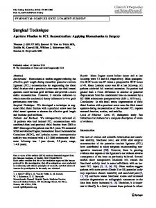
the time resolution were 0.1 sec. Under these conditions 1,500 ft of tape would be produced in every hour of operation and the life-expectancy of the punch would be seriously shortened. A more reasonable approach in some cases is to record the status of the events only if one of them has changed state during the immediately preceding L\t. This of course necessitates that a representation of real time be included on the record each time the event set is recorded. The increase in tape required to record the time will in most cases be more than offset by a reduction in the number of times the event set must be recorded. One of the major problems that arises with this technique is the number of bits required to represent elapsed time since system start-up. This becomes particularly acute with long experimental sessions or small L\ts. The problem is sometimes resolved by establishing a separate time register for each inter-event interval of interest. This avoids the necessity of the large number of bits required to reference all times to system start up, but involves a great increase in the number of time registers and the complexity of the logic necessary to get their contents onto tape. A more reasonable solution in most cases is to work with a single, small time register whose overflow is one of the events to be recorded. A block diagram of the subsystems of the data recorder which has just been described is shown in Fig. I. At system start-up, the Time Register begins to count time pulses from the Clock. Events from the experimental situation are loaded into the Event Register along with indications of overflows of the Time Register. At each L\t the System Interrupt examines the Event Register and Time Overflow. If this register has been incremented, the Timing Control executes a punch cycle. The line Scanner places event and time information on successive lines of the paper tape and clears the Event Register and Time Overflow. A record mark is also punched on the tape to identify the beginning of each recording cycle.
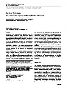
Fig. 1. A block diagram of the proposed recording technique. An Implementation of the Technique A specific implementation of the system in Fig. I is shown in Fig. 2. This system was constructed using a tape punch system and logic modules marketed by BRS Electronics. The cost of the system, less power supplies, was under $1,900. Construction time was less than a day, and the system has been performing without failure for over 1,000 h. This particular system monitors six events, such as lever presses in six Skinner boxes, either continuously or during defined observation intervals, with resolution of up to 0.05 sec. At time zero the run switch is closed, initializing the ring counters, clearing the Time Register, and starting a tuning fork-controlled, astable multivibrator. These timing pulses are counted by seven flip-flops in a binary-counter configuration. When this counter overflows or one of the switches in the experimental situation is closed, a corresponding flip-flop in the Event Register is set up. As soon as the Time Register has been incremented by -the next time pulse, an AND-gate begins a punch
Punch
TPS - 3
TAPE PUNCH SYSTEM
Resistors .a 3.9 K, 1/2 watt Capacitors' .05 mfd .•15 vec
Fig. 2. A schematic diagram of an implementation of the proposed recording technique with solid-state logic modules.
80
Behav. Res. Meth. & Instru., 1968, Vol. 1 (2)
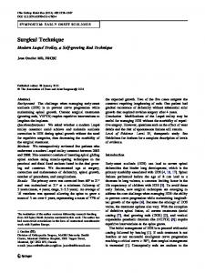
cycle. The three flip-flops in a ring-counter configuration are incremented thus enabling a set of AND-gates to enter the contents of the Event Register and Time Overflow into the Punch Buffer contained in the tape punch system. A "punch" command is then given by the delay output of the one-shot which advanced the ring counter, and the Event and Overflow Register is cleared by the delay output of the one-shot which scanned the contents of this register into the Punch Buffer. A record mark is provided by feeding the scan pulse for this line into the eighth bit of the Punch Buffer. When the punch has completed punching this first line, it supplies a feedback which again increments the ring counter, thus scanning the contents of the Time Register into the Punch Buffer and punching another line of tape. The next feedback from the punch returns the ring counter to its original position. The Time Register then continues to count time pulses until the next event or time overflow occurs, at which point the recording cycle is repeated. Computer Analysisof Output Tapes A gross flow chart for a computer program which recovers IRTs from tapes generated by the system just described is shown in Fig. 3. Elapsed time and a series of variables representing the last time of occurrence of each of the six recorded events are first initialized. A line of tape is then read and, provided the end of tape has not been detected, is examined for a record mark. If a record mark is not found, another line of tape is read, otherwise the line is decoded. Ifthe line indicates a Time Register overflow,
ELAPSED TIME
·0
TIME (,) TIME (2) TIME (3) TIME (4) TIME (5) TIME (6)
·0
·0 ·0
·0
·0 ·0
Fig. 3. A gross flow chart for computer recovery of IRT's from tapes generated by the recording system. Behav.Res. Meth. & Instru., 1968, Vol. 1 (2)
elapsed time is incremented by the capacity of the Time Register (27). The six event bits are then stored for later use and the next line of tape is read. If this line contains a record mark, an error routine is entered which either terminates the run or requests an operator command. Otherwise, the current time is computed as the sum of elapsed time and the current value of the Time Register. The six event bits are then recalled from storage and the IRT of any event which has occurred is computed as the difference between the current time and the time of last occurrence of that event. The time of last occurrence of the event is then updated to the current time and the IRTs are stored. At this point a new record is obtained from the tape and the decoding process is repeated until the end of the input tape terminates the program. This example should suffice to demonstrate the ease of recovery of data from the output tapes produced by the data recording system. Of course many other examples are possible. One important such example would be that in which some of the recorded events are stimuli and some responses, so that response latencies rather than IRTs would be desired. This would be accomplished by subtracting the last time of occurrence of the stimulus from the time of occurrence of its corresponding response. Extensions and Limitations of the Technique The most obvious extensions of the present system involve increasing the size of the time and event registers, and hence the number of tape lines punched in each data recording cycle. Such extensions could be used to increase the resolution of time, or to increase the number of events monitored. However, such extensions soon bring one to the limitations of this technique. In order to insure that the desired time resolution is maintained, a complete recording cycle must occupy less than tH. The number of tape lines that can be punched in one recording cycle is thus given by N = (C) lit, where C is the maximum cycle rate of the punch. For example, the system implemented in an earlier section of this paper could only be extended to 35 events with a 50 cps punch and lit =0.1 sec. With a 500 cps incremental magnetic tape however, about the same number of events could be monitored with a lit of 0.01 sec. In any case, the major advantage of the present technique over that proposed by Ellen and Wilsonlies in the reduction in amount of tape produced when event density is either low or highly variable relative to flt. Essentially the same limitations exist for both systems in respect to the maximum number of events which can be monitored with a given lit and punch cycle rate. One other major extension of the present technique is possible in situations where some or all of the events being monitored cannot occur within the same flt. An example of such a situation would be one in which the events were mutually exclusive alternatives in some multiple-choice task. Under such circumstances, any events which are mutually exclusive within a single flt should be grouped and represented by a 1248 binary code. By so doing, a line of paper tape could represent up to 255 events rather than the 8 events possible under conditions of simultaneous occurrences. REFERENCE ELLEN, P., & WILSON, A. S. Digital recording of simultaneous events in multiple operant chambers. J. expo Awl. Bebav., 1964,7,425-429. NOTE 1. Construction of the system proposed in this paper and computer time for analysis of tapes generated by the system were supported by the Graduate College of the University of Iowa.
81