Behavior Research Methods, Instruments, & Computers 1999,31 (2), 370-375
A computer-controlled olfactometer for fMRI and electrophysiological studies of olfaction TYLER S, LORIG and DAVID G. ELMES Washington and Lee University, Lexington, Virginia and DAVID H. ZALD and JOSE V. PARDO University ojMinnesota, Minneapolis, Minnesota and Minneapolis Veterans Administration Hospital, Minneapolis, Minnesota A design for an inexpensive and reliable olfactometer is presented. The design has several advantages for fMRI and electrophysiology investigators. These advantages include relatively rapid odorant rise times, computer control, multiple odor administration, and no ferrous materials near the subjects. In addition, the device is contamination resistant, and, because the air is neither warmed nor humidified, it is unlikely to become an incubator for bacteria. The olfactometer is constructed of off-the-shelf chromatography parts that require little modification. A variety of instruments have been developed over the past 100 years for the accurate and metered presentation of odors (for a review, see Prah, Sears, & Walker, 1995). Most of these instruments have been developed to meet the demands ofparticular situations or unique experimental settings, with each new need generating changes to existing devices. For instance, Kobal and Hummel (1988) developed an olfactometer with very rapid rise times in order to produce chemosensory event-related potentials. Laing (1986) also produced a unique olfactometer, for behavioral work with odor mixtures, that allowed odors to be introduced in very rapid succession. The advent of fMRI studies of olfactory and chemosensory processes presents a new set of needs, and the olfactometer described here has been developed to meet these needs in a simple and cost-effective manner. The fMRI laboratory presents several important and new demands on an olfactometer. The most obvious and essential is the absence of ferrous metal near the magnet. Ideally, the instrument should have the following features: (1) computer control; (2) effective delivery ofa variety of odors, in series or randomly; (3) production of an odor stimulus ofselectable and reliable duration in a constant airstream, without any additional type of ancillary stimulation (e.g., tactile, auditory); (4) resistance to contamination; (5) durability; (6) ease of operation, refilling, and cleaning; and (7) low cost. The olfactometer described here meets these needs and is relatively easy to construct. With the exception of excluding ferrous metals, The authors thank M. L. Tarpley for his assistance in obtaining the glass balls and A. Livermore for his comments on a draft of this manuscript. We also thank K. Theus, L. Salerno, and S. McGeorge, who were instrumental in the collection ofthe CSERP data. Correspondence concerning this should be addressed to T. S. Lorig, Department ofPsychology, Washington and Lee University, Lexington, VA 24450-0303 (e-mail:
[email protected]).
Copyright 1999 Psychonomic Society, Inc.
these needs are also common to laboratories studying chemosensory event-related potentials (CSERPs) and, in some cases, laboratories that study behavioral responses to odors. Thus, this olfactometer may have applications in a variety of experimental settings.
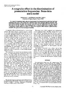
OPERATION The olfactometer is based on a series of computercontrolled Teflon solenoid valves with switching times of 15 msec (Cole-Parmer, Chicago, IL). The arrangement of the valves and flowmeters can be seen in Figure I. Air from a compressor used for home respiratory care (Bunn BA/400A) provides the air supply for the olfactometer's operation. This air is filtered to remove odors and particulates and then enters a series of flowmeters. The constant flow channel goes directly to the subject and provides a carrier airstream that adds to the odorant stream. In addition, the flow through this channel continuously washes the common odor-bearing portions of the olfactometer with clean air. In the nonactive state, the constant flow is combined with the flow through the control channel. During odor administration, the control channel is vented outside the olfactometer, and the flow through one of the odor channels is briefly directed to the subject. After the stimulation interval has ended, the control flow is redirected to the subject. These two flows (constant + control or constant + odor) make up the total amount of air that reaches the subject. If, for instance, one wished to administer a total of 3 Llmin of air, I Llmin might be used in the constant flow channel and 2 Llmin in the control channel. This would mean that the total flow in each ofthe odor channels should also be set to 2 Llmin. Each odor channel (identified in Figure 1 by Roman numerals) consists oftwo flowmeters and an odor vessel.
370
COMPUTER-CONTROLLED OLFACTOMETER
371
Teflon odorant Vessels/Valves
Housing Teflon solenoid NO Valves NC
."""uSI
NC
NC NO - Normally Open
2.0 Umin
NC - Normally Closed
1.0 Umin
Figure 1. Schematic diagram of the olfactometer. Roman numerals refer to the individual channels. Note that the valve for the control flow is normally open.
Only one of the flowmeters is directly connected to the odor vessel. That meter controls the amount of air that actually passes over the odorant. The other flowmeter is used to dilute the airstream. If one wished to reduce by half the concentration of the odor presented to the subject and wished to maintain a total air flow of2 L/min in the odor channel, each flowmeter would be set to deliver 1 L/min. Ifa 75% odor dilution was sought, the flowmeter connected to the odor would be set to 1.5 L/min, and the diluting channel set to 0.5 L/min. If 100% of the air was to be directed through the odorant, that flowmeter would be set to 2 L/min, and the diluting channel to 0 L/min. The total flow in these two odor channels should always match that in the control channel. If this matching is not maintained, differences in flow will result, and the subject may perceive a tactile cue from the flow change. The odor vessels in this design are constructed of small (16 X 50 mm) Teflon cylinders with fittings at each end.
These vessels have been modified to contain two glass ball valves on either side of the odor. The odorant, in solution, is placed on filter paper inside the cylinder. When the computer initiates a stimulation, a solenoid valve opens that passes the air from the flowmeter connected to the cylinder over the odorant and into a Teflon manifold connected to a nosepiece. The positive pressure provided by the solenoid opening causes the ball valves in the odor cylinder to open. The air from the constant channel and the diluent channel also enters the manifold and mixes with the odorized air to dilute the sample before entering the subject's nose. The ball valves in other odor cylinders block the odorized and diluent air from entering any of the other cylinders and force it to be evacuated through the nosepiece. Because the cylinders have no ferrous parts, they can be placed close to the subject when inside the fMRI magnet. This means that the distance from the odorant to the subject is short, and lit-
372
LORIG, ELMES, ZALD, AND PARDO
tle adhesion or contamination can occur in the olfactometer. It also means that the onset of the odor will be faster and more square-wave-like because of decreased diffusion of the odor bolus into the surrounding air inside the tubing. Because the odors are contained near the subject, the tubing supplying the cylinders can be long, and thus, the ferrous elements-such as the solenoids, flowmeters, pump, and chassis of the olfactometer-ean be some distance from the subject and magnet. In our device, the tubing is 7 m long.
CONSTRUCTION With only one exception, the olfactometer is constructed of off-the-shelfparts used primarily in gas chromatography. The only portion ofthe device that requires adaptation is the odor cylinders. These Teflon cylinders are sold as one-way or check valves for chromatography applications (Cole-Parmer) and contain a spring-loaded silicone valve. By unscrewing the cylinder, the valve assembly is easily removed, leaving a 6 X 10 mm cylindrical opening (see Figure 2). This is the area that will contain the odor-saturated filter paper. The ends ofthe Teflon cylinder are OmniFit fittings. A cross-section through this valve reveals that the interior of the fittings is an inverted cone. Because of this configuration, a 4-mm glass ball (Hoover Precision Products, Sault Ste. Marie, MI) placed inside the cone creates a ball valve. In operation, this ball valve prevents the odor from escaping into the nosepiece as long as the odor cylinder is upright in orientation and no positive pressure is present. Because, during high flow administration, the ball may be pushed so far upward that it occludes the exit tubing, a C-shaped ring is placed inside this fitting (see Figure 2). This Cshaped piece is created by cutting a 1.5-mm-Iong arc section from a ring used in the OmniFit fittings. This ensures that the ball is stopped before it closes the exit and leaves sufficient room for outward air flow. To prevent the odor from diffusing down the long section of tubing (toward the flow controller), a second ball valve is needed upstream of the odor. This is accomplished by drilling a cone-shaped opening in the Teflon and inserting a 4-mm glass ball. Since the Teflon is rather soft and easily machined, a sharp spade-type drill bit (0.25 in.) can be used. Although this is a straightforward process, the conical opening must be symmetrical and smooth to ensure that the ball will perfectly occlude the opening. The other portions of the olfactometer are easily assembled, using compression, flange, and hose barb fittings. Tygon tubing (7-mm inner diam) is used to carry air from the air pump to the filter and then to the flow valves. At this point in the system, an activated charcoalfilled canister may be used to wash the incoming air, in order to remove room air odors. The investigator should take care, however, to include several graded particulate filters downstream of the charcoal, to eliminate the associated charcoal dust. The flowmeters chosen for this application were directreading 150-mm glass float flowmeters (2 Llmin maxi-
mum flow) with built-in flow valves (Cole Parmer). These meters offer good precision and are factory calibrated. Mass flow controllers would increase the precision ofthe flow and could easily be substituted, if the investigator's budget permits. At the output ofthe flow valves, Teflon tubing (1.6-mm inner diam) and fittings are used. The flow valves are connected to the three-way Teflon solenoid valves (12 V de; Cole Parmer), which provide the switched airstreams to the odor cylinders. All of the flowmeters and solenoids are housed inside a metal chassis (54 X 40 X 35 em, width X height X depth). The long tubing (7 m in this model) leaving the metal chassis is placed inside a 32-mm outer diameter hose. This hose leads to the four odor cylinders and the Teflon manifold, which are housed in a cylindrical plastic container (85 mm in diameter) placed near the subject's nose. Because of the mechanical ball valves, this cylinder must always be oriented in an upright position. The output of the manifold may be transmitted to the subject in a number of ways, depending on the demands of the experiment. A single tube may be used as a nasal cannula, or a Y adapter may be used for dirhinic administration. The effluent may also be fitted with a lightweight oxygen mask. The solenoid valves are controlled by a computercontrolled 12-VDC relay driver and relays (KeithleyMetrabyte, Staunton, MA, PIO-12 and ERA-8). During normal operation (no stimulation), air from the flowmeters associated with an odor channel enters two different solenoids and is vented into the room air. Air from the control flowmeter enters a single solenoid and is transmitted into the long tubing leading to the subject. During stimulation, all three solenoids are turned on. This causes the control flow to be vented into the room and the odor channels to be transmitted through the odor chambers and to the subject. Because the control flow equals the odor flow, no change in flow is present at the subject. Software for this system will depend on the controller but is exceedingly simple for the PC-based KeithleyMetrabyte boards. In order to set the board for control of the relays, data is written to the control register memory locations that the board occupies in the computer. This initialization sequence can be implemented by sending two lines of BASIC code (other languages that allow direct memory addressing may also be used); the investigator need only send additional data to the memory location corresponding to the channels (port) to turn on and offvarious channels. We use a BASIC OUT statement to turn on the channel and then to turn it off after the administration interval. For instance, the following code fragment turns on odor channel 2 for 1 sec: OUT port, 10 SLEEP 1 OUT port, 0 where port is the address of the relay driver board control port. The argument of 10 for port in the first line turns
COMPUTER-CONTROLLED OLFACTOMETER
373
C shaped ring
4.0mm Glass Balls
_.-I--