MARTIN et al.
SYNTHETIC AUDITORY SPACES – PT. II
A COMPUTER SYSTEM FOR INVESTIGATING AND BUILDING SYNTHETIC AUDITORY SPACES - PART II Geoff Martin1, Jason Corey2, Wieslaw Woszczyk3, and René Quesnel4 Multichannel Audio Research Laboratory (MARLab), McGill University Faculty of Music, Montreal, Canada 1
[email protected] [email protected] 3
[email protected] 4
[email protected] 2
Part 1 of this paper [1] described a preliminary system topology for the creation of auditory “scenes” – two- and three-dimensional synthetic acoustic environments using a MIDI-controlled collection of parallel hardware-based DSP devices. This paper describes Version 2 of this system which includes custom DSP components based on Max/MSP. The system topology, implementation and usage are described.
1 INTRODUCTION For the past four years, a team comprising the Multichannel Audio Research Laboratory (MARLab) at McGill University has been developing a real-time dynamic multichannel acoustics synthesizer dubbed “SceneBuilder” [1]. The mandate of this initiative is the development of a multichannel reverberator with controllers based on perceptual rather than physical attributes of a simulated acoustic environment. Initially comprised of an assembly of off-the-shelf digital mixers and reverb processors controlled using MIDI by a central proprietary software package, the system has grown to include custom digital signal processing (DSP) modules as required. The initial goal of the MARLab was to use SceneBuilder to create virtual acoustic environments called “Scenes” using various parameter configurations based almost exclusively on aesthetic decisions, thus constructing empirical models [2] of various rooms and enclosures. Using relatively simple processes such as delay and equalization in addition to 8 parallel uncorrelated stereo reverberation streams applied to a monophonic anechoic recording, a number of environments were created by combining multiple components of each Scene. These individual components typically corresponded to locations in a concert hall such as the stage and audience areas, although they grew to include more nebulous perceptual components such as the “texture” of sound sources. Although these efforts met with some success, the task proved decidedly monumental. In response to this, the system was modified to Version 2 which included a number of physical model components [2],
AES 19
TH
INTERNATIONAL CONFERENCE
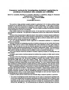
providing the user with a group of parameter settings calculated from known physical laws and principles based on chosen physical attributes. These calculated parameters could then be used as a base set which could be subsequently modified according to aesthetic considerations. The topology of this system permitted the user to modify attributes such as sound source position as well as the location and absorptive characteristics of walls. These variables were used in the automatic calculation and update of various parameters such as the length and spectral balance of reverberation. In addition, the spatial positions of the sound source and individual first- and second-order reflections were correctly located around the listening position using a custom panning algorithm [3]. Appropriate delay times and resulting Doppler shifts were implemented using multiple interpolated delay lines. These settings were subsequently fine-tuned using proprietary perceptual controllers designed for the system to control simultaneously multiple parameters, as well as to adjust them individually. It is this second version of the system which is described in this paper. 1.1 Loudspeaker configuration The loudspeakers are configured in an eight-channel, radially symmetrical system. Each loudspeaker is located at an equal distance to the listener at every 45° starting at front-centre as is shown in Figure 1. The loudspeakers are all full-range systems using matched two-way self-powered speakers, each with a dedicated custom low-frequency extension driver.
1
MARTIN et al.
SYNTHETIC AUDITORY SPACES – PT. II
2.35
sources used for the development and use of SceneBuilder must not contain any reflections or reverberant characteristics of the original recording space. Top ensure a high quality for critical evaluation, monophonic anechoic recordings of real instruments are used, particularly those originally made for the Archimedes project on the Music for Archimedes compact disc [4].
1.14 1.70
1.70
4.35
2 GRAPHIC USER INTERFACE
1.60
1.63
2.39
1.73
Figure 1: Configuration of loudspeakers in the MARLab. The heavy dotted line denotes a heavy black velour curtain. The lighter dotted line inside the loudspeakers is an acoustically transparent but visually opaque curtain. Dimensions are in metres.
Although the SceneBuilder system is used with this loudspeaker configuration, it can be easily modified for other, more standard arrangements. 1.2 Equipment configuration The system makes use of both standard, commercially available hardware signal processing devices as well as custom DSP algorithms, all in various parallel and series arrangements. The DSP itself is performed by a number of devices, including two 350 MHz Macintosh G3’s running Cycling 74’s Max/MSP each with multichannel audio I/O. In addition, a number of standard commercially available effects processors are used. There is a third Macintosh acting as a central MIDI controller for the entire system, using an upgraded version of SceneBuilder Version 1 [1]. 1.3 Sound sources Since the system is used to simulate acoustic spaces through the synthesis and manipulation of various reflections and diffuse field components, the sound
AES 19
TH
INTERNATIONAL CONFERENCE
As was outlined in the introduction, the intention of the development of the SceneBuilder system is to create a real-time synthetic acoustics processor that presents the user with an intuitive interface relating to physical and perceptual characteristics of the room and reverberation. Almost all commercially available room acoustics simulators presently offer control over reverberation characteristics in the frequency and time domains, however, these qualities are not those which are typically used to describe acoustic spaces. The development of SceneBuilder is contingent on the use of the system itself. As a research tool, the system is used to establish the perceptual significance and correlations between various temporal and frequency characteristics of the early reflection components and reverberation tail. These correlations are then implemented as part of the system with the inclusion of a new controller on the graphic user interface. In this manner, the system is used as the principal tool in furthering its development. The user interface is divided into two windows. The first, the Room Window is used to control the size of the enclosure as well as the location of the sound source within its boundaries. The second is the Parameter Control Window which is used to detail various components of the room and reverberation characteristics. 2.1 Room Window The Room Window is used to alter the ratio of the room’s size in two dimensions and the location of the sound source within the enclosure. Figure 2 shows a screen shot of the window in a typical usage. The listener is assumed to be positioned in the virtual room at the location of the crosshairs in the centre of the window. Although this version of SceneBuilder does not permit the user to modify this location, all other components of the space can be altered, thus providing an equivalent, if less intuitive method of 2
MARTIN et al.
SYNTHETIC AUDITORY SPACES – PT. II
moving in the space. The small circle surrounding this point on the screen is for reference purposes only and corresponds to the diameter of the loudspeaker circle in the real monitoring room shown in Figure 1. As will be discussed below, the scale of the room dimensions can be altered using a controller in the Parameter Control Window. Consequently, the circle is included simply to assist the user in visualizing the approximate dimensions of the virtual space, using the real space as a reference. Figure 3: Screen shot of the Parameter Control Window.
2.2.1 Master control area The master control area contains a number of general controls for rapid comparison and balance of the various components of the acoustic environment. The system permits synchronous playback of two multichannel sound files. It is therefore possible to directly compare a recording made in a real reverberant space with an anechoic recording with a synthetic reverberation generated by the system by selecting the Real or Synthetic toggle switches. Figure 2: Screen shot of the Room Window.
The location of the sound source is denoted on the window as a red dot. This is a dynamic location which can be modified using the mouse. The system uses this location to update DSP parameters at an adjustable control rate, typically set at 3 to 10 Hz, depending on the desired response of the system. Although this version of SceneBuilder is implemented for only one sound source, version 3, presently in development, is designed for a number of sources limited only by the DSP capabilities of the processors. The ratio of the room’s size in two dimensions can also be altered using the Room Window. This is accomplished by simply using the mouse to “drag” a wall to a different location. This resolution of the window is 500 x 500 pixels, corresponding to various degrees of resolution in the spatial domain of the virtual space, according to a scaling factor determined in the Parameter Control Window. 2.2 Parameter Control Window The Parameter Control Window provides users with control over a number of characteristics of the synthetic room and its reverberation. The available controls are grouped in the window under six general headings each of which are discussed below. AES 19
TH
INTERNATIONAL CONFERENCE
Figure 4: Close up of the Master control area.
The relative levels of the various components in the synthetic reverberant tail can be adjusted using the output level controllers. Note that, in addition to the Master output control, there are four faders provided, corresponding to the direct sound, early reflections, as well as two different reverberation tails – one for the Stage area and the other for the Room. The distinction between these two will be discussed in Section 3. In addition, toggle switches are provided for muting and soloing various components. 2.2.2 Room construction The physical characteristics of the virtual room are determined using the Room construction area of the window. This section contains two faders which 3
MARTIN et al.
SYNTHETIC AUDITORY SPACES – PT. II
permit the user to adjust the physical dimensions of the space. The Height fader is used to change the ratio of the ceiling height to the width and length of the enclosure, both of which are adjusted in the Room Window. These three dimensions are scaled in unison using the Size Scaling fader. The exact dimensions of the space are listed in metres on the right of the window. Figure 6: Close up of the Early Reflections control area.
2.2.5 Reverberation As will be discussed below, the reverberation times in various frequency bands are calculated using the physical characteristics of the virtual room. These times can be globally scaled using a Time Scaling factor controlled by a fader in the Reverberation control area. This fader can be used independently or it can be linked to the diffusion level controller. Figure 5: Close up of the Room Construction area.
In addition to the room dimensions, the construction materials of the six room boundaries can be individually selected using pop-up menus listing a total of seven different materials: unpainted concrete, tile, wood parquet, drywall, carpet on foam rubber, medium velour and anechoic. This list is essentially arbitrary but was chosen to provide a wide range of frequency dependent absorption characteristics, used in various components of the audio processing as discussed below. 2.2.3 Motion Jitter The system provides the option to apply a simulation of motion to the direct sound component, the details of which are discussed in Section 3.3. The range of this motion is scaled by the user with the Motion Jitter fader. 2.2.4 Early reflections The Early Reflection area of the window permits the user to independently mute the first and second-order reflections using toggle switches. In addition, the amount of simulated diffusion can be scaled using a fader. It is possible to link this diffusion coefficient with a fader used to scale the calculated reverberation time. This is used to simulate the inversely proportional relationship between the level of diffusion of reflections and the reverberation time in a real enclosure [5].
AES 19
TH
INTERNATIONAL CONFERENCE
Figure 7: Close up of the Motion Jitter fader.
Various components of the room’s reverberation tail including the interaural cross correlation are controlled by the Spaciousness Controller. The details of this processing are outlined below in Section 5.2. 2.2.6 Stage width As was discussed earlier, the system provides two discrete reverberant fields for the “stage” and “room” areas. The width of the former is altered using a stage width fader on the control window. The details of this processing are discussed below in Section 5.1. 3 DIRECT SOUND SceneBuilder is a modular collection of different, if occasionally linked, processing functions dedicated to various components of the signal. Separation of these modules is divided along lines in both the
4
MARTIN et al.
SYNTHETIC AUDITORY SPACES – PT. II
spatial and temporal domains, however, for organizational purposes, the former will be used in order to organize this discussion of the system. The direct sound undergoes a minimum of treatment, all of which is determined by its distance and angular location in the system. 3.1 Delay and gain
π π G n = cos(ϑ − φ n ), − ≤ (ϑ − φ n ) ≤ 2 2
(3)
where Gn is the gain of channel n, ϑ is the desired angle to the phantom image and φn is the angular location of loudspeaker n in the listening space. Note π π and the curve matches a that, between − 2 2 simple cosine. At all other locations, the gain value is set to 0.
The delay and gain of the direct sound is determined by the distance (in metres) between the sound source and the listener. The delay is calculated using Equation 1. Delay =
D c
(1)
where D is the distance to the source in metres and c is the speed of sound in m/s. In order to avoid discontinuities in the signal with a moving source, this delay is implemented using an interpolated delay. As has been mentioned in numerous other sources [6], a fortunate advantage of this implementation is that it automatically results in Doppler shifts for sources whose distance to the listener is changing over time. The gain of the system is based on the assumption that a “standard” level for the instrument would be measured at a distance of 1 m. This results in a simple relationship between the distance to the source and the gain applied to the direct sound as is shown in Equation 2. Gain =
1 D
(2)
3.2 Panning The panning of the direct sound is accomplished using a custom panning algorithm described by the authors in a previous paper [3]. This function, labelled “polarity restricted cosine” panning was chosen for two of its characteristics. Firstly, it provides a very small image spread, thus resulting in accurate localization of the direct sound. Secondly, it produces fewer changes in timbre than traditional power panning with dynamic sources, thus smooth changes in source location are achieved. This panning function is described in Equation 3 and shown in Figure 8 AES 19
TH
INTERNATIONAL CONFERENCE
Figure 8: Panning function used for direct sound
3.3 Motion Jitter In preliminary listening tests using the system, it was found that the spatial characteristics of sound sources in real recordings was lost in the SceneBuilder simulation. One reason for this deficiency was the result of the lack of small movements of the sound source. As a result, a function was added to provide a simulation of this movement with a user-controllable scaling coefficient. This movement is a dynamic location change which affects only the angular position of the source. A number of different algorithms were tested in order to achieve the most “natural” sounding source movement including various low-frequency oscillators and random function generators. It was finally decided to use a measurement of the peak value of the audio signal as the continuously updating controller. The audio signal sent to the level detector is processed using a low-pass filter with an adjustable cutoff frequency typically set at 100 Hz. The output of this filter is measured at a rate of 40 Hz and is multiplied by a user-defined scalar determined by the “Motion Jitter” controller
5
MARTIN et al.
The result is a continuously updating dynamic angle which is added to the angular location of the direct sound. Since the peak value of the signal is used as the primary controller, the signal appears to move both right and left of the source position assigned in the Room Window. In order to achieve a more realistic sensation of distance, the range of this angle is scaled to be inversely proportional to the distance to the sound source This function assures that the angular movement is reduced with increasing distance. It is anticipated that the use of multichannel anechoic recordings of sound sources planned for SceneBuilder version 3 will reduce the necessity of this component, however, this hypothesis remains to be evaluated at present. 4 EARLY REFLECTIONS In addition to a dynamically updating direct sound, the system provides a number of continuously variable discrete early reflections whose temporal and frequency characteristics are calculated in real time using the sound source location and the physical characteristics of the enclosure. Due to limitations of the processing system, only eight discrete reflections are calculated. These are all confined to a two-dimensional model of the room (height is not included in this component) and are comprised of the four first-order reflections and the four second-order reflections from parallel wall pairs. This module is designed to include higher-order reflections as faster processors become available. 4.1 Delay and gain The propagation distance of each early reflection is determined using the image method [7]. Each individual delay is subsequently implemented using an interpolated delay following Equation 1, similar to the direct sound. Similarly the basic gain of each reflection is implemented using Equation 2, however there is an additional gain applied to each reflection according to the characteristic of the reflecting surface. 4.2 Simulation of absorptive characteristics In an ideal situation, the particular absorptive characteristics of a reflecting surface could be applied to the reflected signal by convolution through either a calculated filter or a measured impulse response of a reflection from a real example of the material. Again, AES 19
TH
INTERNATIONAL CONFERENCE
SYNTHETIC AUDITORY SPACES – PT. II
due to processing limitations of the present system, this is not possible. Consequently, simulation of the absorptive characteristics of the surfaces are simplified to a single gain factor for full-band absorption and a first-order low-pass filter for additional high-frequency attenuation. The particular characteristics for these two parameters correspond to the seven surfaces materials selected from the pop-up menus in the Parameter Control Window. In the case of the second-order reflections, the characteristics of both surfaces are included in the processing applied to the signal. 4.3 Panning Each early reflection is treated as a discrete signal and is panned using the same algorithm as the direct sound (shown in Figure 8) with an appropriately calculated angle. It should be noted, however, that the Motion Jitter applied to the direct sound has no effect on the early reflections. This decision was made for a number of reasons following a series of preliminary listening tests to determine the benefits of the Motion Jitter system. Note that the variations in the location of the direct sound are in angle only, therefore there is no apparent Doppler shift in the signal since the distance to the listener does not change. However if the varying location were used to update the early reflections the Doppler shift in these components becomes an audible and undesirable artifact of the system. 4.4 Diffusion One primary deficiency of the system is the small number of calculated early reflections. This problem is compounded by the fact that all surfaces are modelled as perfectly specular reflectors. The result of this varies according to the characteristics of the room and the sound source location. In larger spaces with reflective surfaces and the sound source located in the middle of the room, the reflections are audible as discrete delays. In smaller spaces, or where the sound source is located near a reflecting surface, the effect is one of a comb filter. In order to alleviate this problem, a basic simulation of diffused reflections was included. This required a “smearing” of the time response and spatial distribution of the reflections. A configuration of parallel allpass filters to achieve this effect in a system similar to the “filters on specular paths” outlined in Dalenbäck [8]. The difference in the system implemented in SceneBuilder is that the 6
MARTIN et al.
SYNTHETIC AUDITORY SPACES – PT. II
filtering is applied to the output channel after the panning algorithm rather than being applied directly to the reflection before the panning. There are advantages and disadvantages to this system. The primary advantage is that, unlike a filter on a specular path, it simulates the spatial distribution of the reflection. The main disadvantage of the system is that the diffusion characteristics are not applied to a particular surface, rather to the entire collection of reflections. As a result, an impression of a more diffuse field is simulated, but it is not possible to simulate a reflection resulting from a second order reflection from a combination of specular and diffusing surfaces. All allpass filters in the diffusion module have fixed delay times and gain relationships according to predetermined scalars. The user controls a single diffusion coefficient which is multiplied by each individual gain scalar to produce the effect. The particular values of the scalars were chosen to provide a static interaural cross correlation (IACC) value regardless of the direction in which the listener is facing in the monitoring room.
unsatisfactory in that there was a perceived sense of “disembodiment” of the sound source. Despite of the inclusion of appropriately placed early reflected energy, instruments appeared to be unrelated to the surrounding space, a situation rarely encountered in the real world. It was decided that one component which was missing was the sensation of a “halo” of reverberation surrounding the sound source. This is a perceived rather than a physically measurable effect and is labelled the “stage reverb” in the system. The stage reverberation originates from a single channel of an IIR-based digital reverberation unit. The reverberation times of the four frequency bands on this device are assigned using a variable relationship to the reverberation times of the room, typically set to a value of one half. This relationship was chosen based on a series of preliminary listening tests in the MARLab. The output is processed in parallel using two allpass filters in MSP following the form in Equation 5 and resulting in two output channels. y[n] = (-g * x[n]) + x[n-d] + (g * y[n-d])
(5)
5 REVERBERATION The calculation of the RT60 reverberation time is performed using the Sabine equation shown in Equation 4. [5] T = 0.163
V Sα + 4mV
(4)
where T is the reverberation time in seconds, V is the room volume, S is the surface area of the room’s boundaries, α is the average absorption coefficient of all surfaces, and m is the attenuation constant of air. These characteristics are calculated for four independent frequency bands at centres ranging from 125 Hz to 8 kHz using the values and selections in the Parameter Control Window. As was discussed earlier in Section 2.2.5, the four reverberation times can be globally scaled by the user either directly by using a scaling fader, or indirectly through the link with the diffusion scalar. 5.1 Stage reverberation The initial development of this version of SceneBuilder followed the traditional model of direct sound, early reflection cluster and reverberant tail. In initial listening tests, this system proved
AES 19
TH
INTERNATIONAL CONFERENCE
where g is a gain value between 0 and 1 applied to the filter and d is the delay time. The delay time for both filters is set to a constant 30 msec whereas the gains are varied by a user-adjustable coefficient between 0 and 0.75. The gain coefficient is used as the gain for one of the two filters whereas the second filter is fed the same value multiplied by -1. Consequently, this adjustment determines the correlation between the two components from completely correlated when g = 0 to a frequencydependent maximum negative correlation when g = 0.75. Since the intention of the stage reverb is to provide a reverberant field surrounding the sound source, the two channels output from the allpass filters are panned to locations ±45° relative to the direct sound. The absolute angular location is dynamically updated with movements of the sound source in the virtual space. This panning is performed using the function shown in Equation 6 and Figure 9. Gn = 0.5 + 0.5 cos(ϑ − φ n ± 45° )
(6)
This function was chosen as a result of an evaluation by the authors [3] which showed that it produces a wider image spread than either pair-wise power panning or the polarity-restricted cosine function used for the direct sound.
7
MARTIN et al.
SYNTHETIC AUDITORY SPACES – PT. II
the left and right sides. The overall gain of the room reverb processing is controlled by the user with a fader called “Spaciousness”. One reason behind the modulation of the room reverb is to create a reverb that has a constant subtle sense of motion. Because the modulator is derived from the original input signal it is less noticeable as a separate effect, and more successful at integrating with the music being processed. This is partly due to the fact that changes in the spatial characteristics of the reverberation are synchronous with changes in the amplitude of the musical program material.
Figure 9: Panning function used for left channel of stage reverberation. The right channel is symmetrical to this curve around 0°.
5.2 Room reverberation The room reverberation is generated from a single channel of a second IIR-based reverberation unit. The direct anechoic signal is fed to the reverb unit and returned to a second Macintosh G3 for additional processing and routing to the eight loudspeakers. Each reverb send to the eight loudspeakers is processed through an individual allpass filter. The reason for choosing to use only one channel of reverberation was to have complete control over the amount of correlation between the feeds to the eight channels. The feedback gain of each allpass filter is modulated differently according to the RMS of the musical input signal. To calculate the RMS the signal is first squared and subsequently lowpass filtered with a cutoff frequency of 8Hz. The output of the lowpass filter is sampled at a rate of 50Hz. The square root of the sampled output is then lowpass filtered with a cut-off frequency of 4Hz. This signal serves as a modulator for the feedback gain of each of the eight allpass filters. Reverb signals that are fed to the left channels (i.e., left front, left side, and left surround) receive a modulation signal between –0.75 and 0, whereas those modulating the right channels (i.e., right front, right side, and right surround) receive a modulation signal between 0 and 0.75. The centre front and rear channels have a constant feedback gain of 0. The allpass filters alter the phase component of the left and right signals in opposing polarities. The result of this processing is an increase in perceived reverb width as the level of the musical signal increases, due to the decrease in correlation between AES 19
TH
INTERNATIONAL CONFERENCE
The eight individual levels of the room reverberation are adjusted in real time according to the location of the direct sound. Equation 7 and Figure 10 illustrate the gain function of one channel of the room reverb relative to the angular separation of the direct sound. This gain function serves to reduce the level of the room reverberation at the angle of the direct sound and stage reverb, thereby situating the room reverberation at 180° relative to the source location. Gn = 0.75 + 0.25 cos(ϑ − φ n + 180° )
(7)
Figure 10: Gain function used for room reverberation
6 CONCLUSION The SceneBuilder system is in a state of continual development and evolution. This paper describes the addition of physical model components to the processing system permitting the rapid construction of synthetic acoustic spaces. This enhances the capabilities of the system as a research tool used in the investigation of subjective vs. objective relationships in multichannel audio, in developing spatial ear training programs, and in testing different 8
MARTIN et al.
enhancements and strategies for spatial synthesis. In addition, the ability to dynamically alter room and sound source characteristics in real time permit the comparison of various physical and perceptual components. These are tested using direct comparison of recordings made in existing spaces against the same space modelled using SceneBuilder. Repeatability of test signals and the precise composition of their various components can be fully controlled and used to provide additional data for future experimental design.
SYNTHETIC AUDITORY SPACES – PT. II
[8] Dalenbäck, B.-I., Kleiner, M., & Svensson, P. (1994) “A Macroscopic View of Diffuse Reflection,” Journal of the Audio Engineering Society, 42(10): 793-805, October.
7 ACKNOWLEDGEMENTS The authors would like to thank the following people and affiliates for making this research possible. NSERC – the National Sciences and Engineering Research Council of Canada. Dr. Søren Bech, Poul Praestgaard and Bang & Olufsen A/S. Kim Rishøj, Morten Lave, Thomas Lund and t.c. electronic A/S. Dr. Takeo Yamamoto and Pioneer Corporation. 8 BIBLIOGRAPHY [1] Quesnel, R., Woszczyk; W., Corey, J.; & Martin, G. (1999) “A Computer System for Investigating and Building Synthetic Auditory Spaces – Part 1,” 107th Conference of the Audio Engineering Society, preprint no. 4992, New York, 24-27 September. [2] Edwards, D., & Hamson, M. (1989) Guide to Mathematical Modelling, CRC Press, Boca Raton, Florida. [3] Martin, G., Woszczyk; W., Corey, J.; & Quesnel, R. (1999) “Controlling Phantom Image Focus in a Multichannel Reproduction System,” 107th Conference of the Audio Engineering Society, preprint no. 4996, New York, 24-27 September. [4] Bang & Olufsen (1992) Music for Archimedes, CD B&O 101 [5] Kutruff, K. H. (1991) Room Acoustics, Elsevier Science Publishers, Essex. [6] Roads, C., ed. (1996) The Computer Music Tutorial, MIT Press, Cambridge. [7] Allen, J.B., & Berkley, D.A. (1979) “Image Method for Efficiently Simulating Small-Room Acoustics,” Journal of the Acoustical Society of America, 65(4): 943-950, April.
AES 19
TH
INTERNATIONAL CONFERENCE
9