A conceptual framework for component-based system metrics definition Camelia S¸erban and Andreea Vescan and Horia F. Pop Babes¸-Bolyai University, Department of Computer Science 1 Kogalniceanu St., 400084, Cluj-Napoca, Romania Email: camelia, avescan,
[email protected] Abstract—The lack of standard formalism for defining software metrics has led to ambiguity in their definitions which hampers their applicability, comparison and implementation. In this paper we propose a conceptual framework for defining metrics for component-based systems. The proposed approach defines a metamodel of the corresponding context where metrics are applied. The use of algebraic sets and relations allows us to formally define metrics, thus providing clear and precise definitions.
I. I NTRODUCTION As today’s software applications are more complex and software failure is more critical, a means of effectively measuring the quality of software products is needed. Due to this reason, software metrics started to be part of any software development process. It becomes easier to estimate and plan new activities based on measurement, to control the progress and to improve the process, making it more cost-effective in the future. Software metrics can help to fully understand both the design and architecture information of the software system, aiding to discover design flaws by relevant evaluation throughout the software development life cycle. They can also assist the task of software test. And last but not least, software metrics, especially reusability metrics based on object-oriented metrics, can assess the quality and reusability of software components. Efficiently extracting potentially useful or reusable modules or components in legacy system may be assisted by the use of software metrics. Although a large number of metrics have been proposed by researchers to assess software systems, they pose some problems, the most important being that metrics definitions are imprecise, incomplete, lacking a formality degree used to define them. When metrics are informally expressed, using natural language, people using metrics can interpret them in several ways, two distinct teams can obtain completely different results when applying a particular metric to the same system. Without clear and precise definitions of metrics, it may be impossible to consistently develop tools to collect those metrics, or to discuss their properties in a mathematically sound way. For example, consider the following natural language definitions, borrowed from [13]: “Component Resource Utilization Metric (CRUM): Resource utilization metric should measure the utilization of target computer resources as a
percentage of total capacity.” The metric is defined as a ratio between used and available resources. It completely omits which resources should be measured and how they could be measured. The lack of formal definition of metrics is due to the following reasons. Their definitions are often presented without the corresponding context. The underlying metamodel upon which the concepts and their interrelationships are defined is missing. Finally, metrics definitions are performed without a formal approach that uses the previously mentioned metamodel as contextual input. Therefore, in order to overcome these problems, we strive to define a conceptual framework that defines metrics for component-based systems. The metrics definitions are drawn from the context delineated for the meta-model presented in Section II. They rely on the accurate formalism of algebraic sets and relations, knowledge assumed as familiar since the first stages of our studies. Thus, the definitions of the metrics which can be expressed through our framework are unambiguous, straightforward and language independent. Section III provides as a proof of concept, some metrics definitions examples using the proposed approach. Related work on formal definition of metrics are stated in Section IV. II. A META MODEL FOR C OMPONENT-BASED S YSTEM As we have mentioned before, in order to formally define metrics we have to specify the corresponding context where they are applied, defining a meta-model as the contextual input. A meta-model is a model of a model describing a software system [1], [7]. It defines the language used to model a software system. The following definition defines a metamodel for a component-based software system. Definition 1: (A meta-model for Component-Based System) The 3-tuple (E, P rop(E), Rel(E)) is called a meta-model for Component Based System, where: • E represents the set of system entities; • P rop(E) defines the properties of the elements from E; • Rel(E) represents the relations between the entities set E. The elements E, P rop(E), Rel(E), mentioned in Definition 1 will be next described in detail, using terms of algebraic sets and relations.
A. System entities.
•
P aram(CR) =
S
P aramc - the set of all pa-
c∈Comp(S)
Consider a repository of components CR, CR = {c1 , c2 , ..., cnoCR }. A subset of components Comp(S) = {c′1 , c′2 , ..., c′noComp }, Comp(S) ⊆ CR, are selected in order to construct a software system S that has to provide a set of services Serv(S) = {s1 , s2 , ..., snoServ }. According to Szyperski [15], “a software component is a unit of composition with a contractually specified interface and explicit context dependencies only.” Furthermore, it “can be deployed independently and is subject to composition by the third parties.” Therefore, components internal design and implementation are strongly encapsulated and the component exclusively communicates with other components through its interfaces, leading to inter-component dependencies. Interfaces provide inputs/outputs as parameters. These parameters define the signature of an interface. In addition to interfaces, a software component may have a number of configurable parameters or properties externally observable. A common use of component parameters is for component customization and configuration at the time of use. It should be noted that certain component parameters can only be observed, but not changed. Therefore, each component c ∈ CR is specified as a set of provided interfaces (functionalities, services) P Ic = {pic,1 , pic,2 , ..., pic,noP Ic }, a set of required interfaces RIc = {ric,1 , ric,2 , ..., ric,noRIc } and the dependencies (context) between its interfaces provided and required. Consider the following notations: S • Ic = P Ic RIc -the set of interfaces of component c ∈ CR; S • P I(CR) = P Ic - the set of all provided interfaces c∈CR
•
from CR; S RI(CR) = RIc - the set of all required interfaces c∈CR
•
from CR; S I(CR) = P I(CR) RI(CR) - the set of all interfaces from CR; S P Ic - the set of all provided interP I(S) =
•
faces from S, S Serv(S) ⊆ P I(S); RIc - the set of all required services RI(S) =
•
c∈Comp(S)
c∈Comp(S)
•
from S; I(S) = P I(S) ∪ RI(S) - the set of all interfaces from S; P aramc (i) = {pc,1 , pc,2 , ..., pc,N oP aramci } - the set of all parameters that appear in the signature of interface i, i ∈ Ic ; EPc = {epc,1 , epc,2 , ..., epc,noEPc } - the set of external parameters of S the componentSc; P aramc = P aramc (i) EPc - the set of all pa-
•
rameters of component S c; P aramc ,- the set of all paramP aram(S) =
•
•
•
i∈Ic
c∈Comp(S)
eters from the system S;
rameters from repository CR; Based on the above notations, the system entities set is defined as in equation 1: E = Comp(CR) ∪ I(CR) ∪ P aram(CR).
(1)
B. Properties of system entities. As we have mentioned before, the second element of our meta-model is the set of properties of the system’s entities. We denote this set by P rop(E). Because current approach refers to three types of system entities (component, interface, parameter), each type having its own set of properties, we define a model in order to specify the properties of entities of a generic type T . Properties of generic type entities. Formal specification. • Let us consider a set of entities A = {a1 , a2 , ..., ak } of a generic type T and a set of properties defined on this type, P ropT = {P1 , P2 , ...PnoPT }; • Each property Pi from P rop(T ), 1 ≤ i ≤ noPT , have a set of values Pi = {vi1 , vi2 , ...viN oVi }; • Each entity ai from A, 1 ≤ i ≤ k, will be assigned to a value from the cartesian product, P1 × P2 × ... × PnoPT , assignment that will be formally expressed as follows: P ropV alT : A → P1 × P2 × ... × PnoPT . With the above mentioned notations and remarks, we introduce the following definitions: Definition 2: An element vi of the vector P ropV alT (aj ) = (v1 , v2 , ..., vnoPT ) is called the value of property Pi corresponding to entity aj , shortly denoted as vi = aj .Pi . Definition 3: P ropV alT (A) = {P ropV alT (aj )|i = 1, k} is called the set of properties values corresponding to entities set A of type T . Definition 4: The 4-tuple P ropT,A = [T, A, P ropT , P ropV alT (A)] is called properties specification corresponding to a set of entities A of type T . In what follows, we apply this model in order to specify the properties for each type of system entities from our metamodel: component, interface, parameter. In Table I we describe the abbreviations used for the above mentioned entities type. Entity type Abbreviation
component C
interface I
parameter P
TABLE I A BBREVIATION OF SYSTEM ENTITIES TYPE
As we have mentioned before, interfaces are fundamental for a component because they characterize component functionality. Beside the functional properties, there are other features of a software component, its non-functional properties like cost, CMM Level, quality attributes, such as reusability, functionality, security, performance and reliability. We argue
that quality attributes of a component are most often not a constant property. Muchmore, the quality of a component heavily depends on the specific usage context. Therefore, the quality attributes of a component is quantified by the user of the component, according to his system requirements and context. Taking all these into account, we next give the specification for entity of type component. Definition 5: (Specification of properties for entities of type “component”) The 4-tuple, P ropC,CR = [C, CR, P ropC , P ropV alC (CR)] is called specification of properties for entities of type“component”, where: • P ropC = {V endorCM M Level, Cost, V ersion}; • CM M Level = {Initial, M anaged, Def ined, Quantitatively, Optimized}; • Cost = [a1 , b1 ], cost values range; • V ersion = {vi |i = 1, noV }. It is important to point out that the set of component properties, P ropC , is incomplete. Other data, such as those regarding the environment in which the component is used, can be added later on in the process. These statements argue that the proposed model has the scalability property. As we have mentioned before, interfaces are fundamental for a component because they characterize component functionality. The interface signature of a component comprises operations and events. The operations capture the dynamic behavioral capability of the component, and represent the service/functionality that the component provides. Besides proactive control (usually in the form of explicit operation invocation or message passing), another form of control used to realize system behavior is reactive control (usually in the form of event-driven implicit operation invocation or message passing). It is often the case that certain aspects of a system are better captured through proactive control via operations, while other aspects of the system are better captured in the form of reactive control via events. To facilitate reactive control, a component may generate events from time to time, which other components in the system may choose to respond to. In this type of event-based component interactions, there may be none or many responses to an event, and they may change as time goes on. As such, this model of interaction allows communication channels to be established dynamically, and gives the system the capability of dynamic configuration. Taking these into account, we can give the formalization for entities of type “interface” and “parameter”. Definition 6: (Specification of properties for entities of type “interface”) The 4-tuple,
Definition 7: (Specification of properties for entities of type “parameter”) The 4-tuple, P ropP,P aram(CR) = [P, P aram(CR), P ropP , P ropV alP (P aram(CR))] is called specification of properties for entities of type“parameter”, where: • • • • •
P ropP = {Kind, T ype, Aggregation, Access}, Kind = {external, return − value, argument} T ype = {predef ined, user − def ined, library}, Aggregation = {simple, array, f ile}. Access = {read − only, write − only, read − write}
C. Relations between system entities. In this section we specify two type of relations that exist between the entities of the meta-model defined before. Dependency relations. In order to specify components dependencies we introduce the following definitions. Definition 8: A dependency for a component c, c ∈ CR, is a pair (p, r), p ∈ P Ic and r ∈ RIc , with the meaning that in order to provide interface p, component c requires an interface r from other component, we shortly denote this relation as p DRc r. Definition 9: The set of all dependencies of a component c, c ∈ CR, is a binary relation DRc ⊆ P Ic × RIc , defined as (p, r) ∈ DRc ⇐⇒ p DRc r. It is important to mention that there are interfaces without dependencies. The services of these interfaces are the services that handle input data. Additional notations are needed: •
•
DRc (p) = {(p, r)|r ∈ RIc ∧ p DRc r}, p ∈ P Ic the dependencies setSof the provided interface p, p ∈ P Ic ; DR(CR) = DRc is the set of all dependencies c∈CR
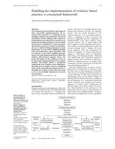
from the repository CR; Figure 1 describes the dependency relations for a component c with the provided services P Ic = {pu , pv , pt } and required services RIc = {ri , rj , rk }. The dependencies between the provided and required interfaces (the contexts) are also graphically presented: different type of line is used for each requiredprovided dependency. DRc ri pu
rj
√
rk √
pv
√
pt
√
√
Component c ri rj rk
pu pv pt
P ropI,I(CR) = [I, I(CR), P ropI , P ropV alI (I(CR))] is called specification of properties for entities of type “interface”, where: • P ropI = {Kind, F unctionality}, • Kind = {operation, event}, • F unctionality = {provided, required}.
Fig. 1. Specification Table of the Component Dependencies Requirements for component c with the DRc (pu ) = {(pu , ri ), (pu , rk )},DRc (pv ) = {(pv , rj ), (pv , rk )} and DRc (pt ) = {(pt , rj )} (left side of the figure) and the graphical representation of the contexts (right side of the figure).
Connection relations. The connection happens when a component provides an interface and other component uses it. We define two kind of connection relations for a component c: in–connection relations, when component c uses an interface from other component, and out-connection relations, when component c provide an interface for other component. It is important to mention that the connection relations are identifiable as the Comp(S) set is constructed. Next, we formally define these connection relations. Definition 10: Consider c, d ∈ Comp(S). We say that c is in–connected with d within the system S, if (∃) r ∈ RIc such that r ∈ P Id and component c uses the required interface r from component d. We briefly denote this relation as c CRin,r d. Definition 11: Let CRin,c = {(r, d)|(r ∈ RIc , d ∈ Comp(S)) ∧ c CRin,r d} be the set of all in–connections of component c, c ∈ Comp(S). Definition 12: Let CRin,c (p) = {(r, d)|(r ∈ RIc , d ∈ Comp(S)) ∧ c CRin,r d ∧ (p, r) ∈ DRc }, c ∈ Comp(S), p ∈ P Ic be the set of all in–connections of component c regarding with provided interface p. Definition 13: Consider c, d ∈ Comp(S). We say that c is out–connected with d within the system S if (∃) p ∈ P Ic such that p ∈ RId and component d uses r from component c. We shortly denote this relation as c CROut,p d. Definition 14: Let CRout,c = {(p, d)|(p ∈ P Ic , d ∈ Comp(S)) ∧ c CRout,p d} be the set of all out–connections of component c, c ∈ Comp(S). S CRin,c be the set Definition 15: Let CR(S) = c∈Comp(S)
of all connections of the software system S. There are four types of connection using provided and required interfaces: provided operation to required operation, provided operation to required event, provided event to required operation, and provided event to required event. See Figure 2.
III. F ORMAL DEFINITION OF METRICS Throughout the following lines, we exemplify the definition of some metrics proposed by Hoek et al. [14], and by Narasimhan and Hendradjaya [16]. Overall, they aim to assess the fitness of components in a specific architecture. These metrics are context specific, in the sense that the same component will have a different metric value depending on the assembly where it is being integrated. Consider the following notations: • OCRout,c = {e|e ∈ CRout,c ∧ e.Kind = operation}the set of out - connection operation relations of component c; • OCRin,c = {e|e ∈ CRin,c ∧ e.Kind = operation}-the set of in - connection operation relations of component c; • OP Ic = {e|e ∈ P Ic ∧ e.Kind = operation -the set of provided operation of component c; • ORIc = {e|e ∈ RIc ∧ e.Kind = operation -the set of required operation of component c. In what follows we have formally specified some metrics using our framework. Additional comments have been added to best explain differences between informal and formal definitions. Metric Name Informal definition
Provided Service Utilization (PSU) [14]
Formal definition Comments
P SU (c) =
PSU metric represents the ratio of services provided by the component which are actually used.
•
•
card(OCRout,c ) , card(OP Ic )
c ∈ Comp(S)
PSU denotes the extent to which the assembly uses the services provided by the component. Although a low value of PSU may occur if a component was built for reuse, it also means that the component carries a large amount of extra functionality that is not required by the assembly; In our formalization we assume operation interfaces as services that a component can provide, or require. TABLE II PSU M ETRIC D EFINITION
Component d Component c
Component d Component c
Component c
Component d
Metric Name Informal definition
Required Service Utilization (RSU) [14]
Formal definition Comments
RSU (c) =
PSU metric represents the ratio of services required by the component which are actually used.
•
Component d Component c
•
Fig. 2. The four types of connections: provided operation to required operation, provided operation to required event, provided event to required operation, and provided event to required event.
card(OCRin,c ) , card(ORIc )
c ∈ Comp(S)
RSU denotes the extent to which a component requires services that are available in the component assembly. Ideally, RSUs value should be 1; In our formalization we assume operation interfaces as services that a component can provide, or require. TABLE III RSU M ETRIC D EFINITION
Metric Name Informal definition
The Compound Provided Service Utilization (CPSU) [14] The Compound Provided Service Utilization (CPSU) represents the ratio of services provided by the components in the assembly which are actually used. P
Formal definition Comments
CP SU (S) =
Metric Name Informal definition
Average Interaction Density of Software Components (AIDC) [16] The Average Interaction Density of Software Components (AIDC) represents the sum of IDC for each component divided P by the number of components.
Formal definition Comments
AIDC(S) =
IDC(c)
card(OCRout,c )
c∈Comp(S)
P
card(OP Ic )
c∈Comp(S)
Low values of CPSU may indicate an unbalanced architecture, particularly when combined with high values of CRSU, as this implies that the assembly is larger than needed.
Compound Required Service Utilization (CRSU) [14] The Compound Required Service Utilization (CPSU) represents the ratio of services required by the components in the assembly which are actually used. P card(OCRin,c )
Formal definition Comments
CP SU (S) =
c∈Comp(S)
P
card(ORIc )
c∈Comp(S)
A low value for CRSU suggests that the assembly is not self-sufficient, as more components would are required to provide the remaining functionality. TABLE V CRSU M ETRIC D EFINITION
Metric Name Informal definition Formal definition Comments
Interaction Density of a Component (IDC) [16] The Interaction Density of a Component (IDC) is defined as a ratio of actual interactions over potential ones S IDC(c) =
card(CRin,c CRout,c ) , card(Ic )
c ∈ Comp(S)
IDC is somewhat similar to a combination of PSU with RSU but Narasimhan and Hendradjaya consider the usage of both operations and events as interactions. TABLE VI IDC M ETRIC D EFINITION
Metric Name Informal definition
Incoming Interaction Density of a Component (IIDC) [16] The Incoming Interaction Density of a Component (IIDC) is defined as a ratio of actual incoming interactions over potential ones
Formal definition
IIDC(c) =
card(CRin,c ) , card(RIc )
c ∈ Comp(S)
TABLE VII IIDC M ETRIC D EFINITION Metric Name Informal definition
Outgoing Interaction Density of a Component (OIDC) [16] The Outgoing Interaction Density of a Component (OIDC) is defined as a ratio of actual outgoing interactions over potential ones
Formal definition
OIDC(c) =
card(CRout,c ) , card(P Ic )
c ∈ Comp(S)
TABLE VIII OIDC M ETRIC D EFINITION
card(Comp(S)
Narashiman and Hendrajaya suggest that AIDC can be used as an explanatory variable for assembly complexity, so that a lower value may indicate that less effort can be committed to software risk analysis. TABLE IX IDC M ETRIC D EFINITION
TABLE IV CPSU M ETRIC D EFINITION Metric Name Informal definition
c∈Comp(S)
IV. R ELATED WORK ON FORMAL DEFINITION OF METRICS Several authors have attempted to address the problem of imprecise metric definitions, most of these approaches deals with metrics for object oriented design. Briand et al. [11], [12] propose two extensive frameworks for software measurement, one for measuring coupling and the other for measuring cohesion in object-oriented systems. While this framework allows for the unambiguous definition of coupling and cohesion metrics, new frameworks must be developed for other types of metrics. Therefore their scalability is hampered. Another approach put forward by Reiβing [10] involved the proposal of a formal model on which to base metric definitions. This model is called ODEM (Object-oriented DEsign Model) and consists of an abstraction layer built upon the UML meta-model. However, this model can only be used for the definition of design metrics and does not solve the ambiguity problem as the abstraction layer consists of natural language expressions. Baroni et al. [8] propose the use of the OCL and the UML meta-model as a mechanism for defining UML-based metrics. They have built a library called FLAME (Formal Library for Aiding Metrics Extraction) [9] which is a library of metrics definitions formulated as OCL expressions over the UML 1.3 meta-model. Regarding the formalization of metrics definition for component-based system, a suite of three papers have presented a formalization of metrics for CBSE, using OCL language. The papers [18], [19] focus on metrics applicable to components in isolation, using different metamodels (CCM and UML 2.0, respectively), to illustrate the expressiveness of the formalization approach. In [17] the authors present a similar formalization focused on component assemblies, using the CCM metamodel. We believe that this approach provides a useful mechanism for the precise definition, but the majority of software designers may not have the required background to understand the OCL formalism. Some limitations of this metamodel are those that it does not include abstractions for representing component assemblies, it can not support to be scalable in order to define any type of metric for componentbased system. In order to overcome these limitations a new
model have to be defined. In this paper, we start from the approach proposed by Briand et al. We extend this approach and integrate it within a corresponding meta-model for component-based systems. The proposed approach is general and scalable in order to define any metric for component based system, its constituent elements – the system entities, their properties and relations– are formally specified, in terms of algebraic sets and relations, knowledge considered known since the first stages of our studies. The metrics that can be expressed using our metamodel have definitions that are unambiguous, simple and language independent. V. C ONCLUSION AND F UTURE W ORK We have presented in this paper a new approach that address the issue of formal definition of metrics for componentbased systems. The main advantage of our framework is its scalability, new entities can be added or new properties for the existing entities, for example new properties for components. Further work can be done in the following directions: • to extend the approach in order to define any metric found in literature for component-based systems; • to define a library for component-based systems metrics definitions; • to integrate this approach as a component, into a model for component-based systems assessment; ACKNOWLEDGMENT This research has been supported by the Romanian CNCSIS through the PNII-IDEI research grant ID 550/2007. R EFERENCES [1] J. Warmer, A. Kleppe, and W. Bast,: MDA Explained: The Model Driven ArchitecturePractice and Promise. Addison-Wesley, 2003. [2] C. Serban, A. Vescan, and H.F. Pop. Component selection based on fuzzy clustering analysis. Creative Mathematics and Informatics, 17 (3), pp. 505 – 510, 2008. [3] A. Vescan, A Metrics-based Evolutionary Approach for the Component Selection Problem. Proceedings of the 11th International Conference on Computer Modelling and Simulation, 25 - 27 March, Cambridge, England, ISBN: 978-0-7695-3593-7, pp. 83 – 88, 2009. [4] C. Serban, A. Vescan, H. F. Pop, A new Component Selection Algorithm Based on Metrics and Fuzzy Clustering Analysis. Proceedings of the 4th International Conference on Hybrid Artificial Intelligence Systems, 10 12 June, Salamanca, Spain, LNCS Vol. 5572, ISBN: 978-3-642-02318-7, pp. 621 – 628, (2009). [5] W. Li and S. Henry, Object-oriented metrics that predict maintainability. Journal of Systems and Software, 23(2), 111–122, 1993. [6] T.J. McCabe, A Complexity Measure. IEEE Transactions on Software Engineering, 2(4), 308–320, 1976. [7] R. Marinescu, Measurement and quality in object-oriented design. Ph.D. thesis in the Faculty of Automatics and Computer Science of the Politehnica University of Timisoara, 2003. [8] A. Baroni, S. Braz and F. Brito e Abreu , Using OCL to formalize objectoriented design metrics definitions. Proceedings of ECOOP Workshop on Quantitative Approaches in Object-Oriented Software Engineering, Spain, 2003. [9] A. Baroni, S. Braz and F. Brito e Abreu , A formal library for aiding metrics extraction. Proceedings of ECOOP Workshop on Object-Oriented Re-Engineering, Darmstadt, Germany, 2003. [10] R. Reiβing, Towards a model for object-oriented design measurement. Proceedings of ECOOP Workshop on Quantative Approaches in ObjectOriented Software Engineering, 2001.
[11] L. Briand, J. Daly and J. Wust, A Unified Framework for Coupling Measurement in Object-Oriented Systems. IEEE Transactions on Softw. Engineering, 25(1), 91-121, 1999. [12] J. Wust, L. Briand, J. Daly, A Unified Framework for Cohesion Measurement in Object-Oriented Systems. Empirical Software Engineering: An International Journal, 3(2), 65-117, 1998. [13] N. S. Gill and P. S. Grover, Component-Based Measurement: Few Useful Guidelines. ACM SIGSOFT Software Engineering Notes, vol. 28, pp. 4– 4, 2003. [14] A. v.d. Hoek, E. Dincel, and N. Medvidovic, Using Service Utilization Metrics to Assess and Improve Product Line Architectures. 9th IEEE International Software Metrics Symposium (Metrics’2003), Sydney, Australia, 2003. [15] C. Szyperski, Component Software, Beyond Object-Oriented Programming. ACM Press, Addison-Wesley, 1998. [16] V. L., Narasimhan, and B. Hendradjaya, A New Suite of Metrics for the Integration of Software Components The First International Workshop on Object Systems and Software Architectures (WOSSA’2004), South Australia, Australia, 2004. [17] M. Goulao, and F.B. Abreu, Composition Assessment Metrics for CBSE. In Proceedings of the 31st Euromicro Conference - Component-Based Software Engineering Track. Porto, Portugal: IEEE Computer Society. (2005) [18] M. Goulao, and F.B. Abreu, Formal Definition of Metrics upon the CORBA Component Model. First International Conference on the Quality of Software Architectures (QoSA2005). [19] M. Goulao, and F.B. Abreu, Validao Cruzada de Mtricas para Componentes. IEEE Transactions Latin America, vol. 3, no. 1, 2005.