that consists of two parts: a Gaussian pyramid generator and a correlation-based ... pyramids for 512 Ã 512 images at 30 frames per second, and performs a ...
A Configurable Computing Approach Towards Real-time Target Tracking Bharadwaj Pudipeddi, A. Lynn Abbott, and Peter M. Athanas The Bradley Department of Electrical and Computer Engineering Virginia Tech Blacksburg, Virginia 24061-0111, USA Abstract. Traditionally, tracking systems require dedicated hardware to handle the computational demands and input/output rates imposed by real-time video sources. An alternative presented in this paper uses configurable computing machines, which use interconnected FPGAs to provide fine-grain parallelism and reconfigurability so that high-speed performance is possible for many different applications. The efficacy of such architectures to image-based computing is illustrated here through the implementation of a tracking system that consists of two parts: a Gaussian pyramid generator and a correlation-based tracker. The pyramid generator converts each input image to a hierarchy of images, each representing the original image at a different resolution. An object is tracked on successive frames by a coarse-to-fine search through this image hierarchy, using the sum of absolute differences as the matching criterion. Splash 2 performs these operations at rates of 15 or 30 frames per second. Its performance therefore rivals that of application-specific systems, although the architecture is inherently general-purpose in nature.
1. Introduction The purpose of a visual tracking system is to follow a moving object through a sequence of images. Visual tracking is needed in many applications, including surveillance, autonomous vehicle navigation, robotic gaze control, and missile guidance. Unfortunately, most of these tasks require large amounts of image data to be processed at high speeds. Because typical general-purpose computing platforms are not capable of meeting these demands, system designers have traditionally developed special-purpose hardware that is carefully tailored to meet the needs of a specific task. The problems associated with the use of application-specific hardware are well known, however: lengthy design cycles, high cost, and inability to accommodate problems that are not specifically addressed in the design. Configurable computing machines (CCMs) have emerged as an attractive alternative to high-performance embedded computing. CCMs retain a general-purpose nature, yet can be configured to offer performance that rivals application-specific hardware. A single CCM platform can be quickly reconfigured to implement such vastly different operations as median filtering [Abbo95], genetic database search, the
two-dimensional Fourier transform, or even control-driven processing. CCMs are typically characterized by high-capacity data paths and programmable interconnects between processing elements (PEs). Example CCMs are Splash 2 [Atha95], and Spyder [Isel95]. This paper describes the implementation of a real-time visual tracking system using the Splash 2 configurable computing machine. The system generates image pyramids for 512 × 512 images at 30 frames per second, and performs a coarse-to-fine search to track the movement of an object in the field of view. The implementation combines pipelining, data recirculation, and SIMD operation to demonstrate the utility of the configurable computing approach on data-intensive image-analysis tasks.
2. Coarse-to-fine tracking The visual tracking problem may be stated as follows: given an image I n obtained at time n, and given the row and column location (r, c) for a target of interest in that image, determine the new row and column location for the same target in the subsequent image. Typically, this requires a search within I n+1 that begins near location (r, c), and this process repeats for each successive image using the most recent knowledge of target position to select the starting point for the new search. For the implementation described here, a simple area-based matching method is used for searching. A sub-image S of size w × w (here, w = 16) is extracted from the reference image I n , and is compared with w × w windows within I n +1 . For each window that is chosen, the sum of absolute differences (SAD) of pixel values are computed, and the window minimizing this criterion indicates the new target location within. This may be represented as w−1 w−1
d (x, y ) = ∑ ∑ S (r , c ) − I n +1 (r − x , c − y ) r =0 c =0
where the offset (x, y) that minimizes d determines the best-match location. In this implementation, x and y are both constrained to lie in a small range which yields a total search window in I n+1 of size 32 × 32. A problem with this simple matching method is that false matches may result because of noise, rapid object movement, or a host of other problems. To combat this, a common approach is to employ a hierarchical search method that begins with an initial search over the entire image at very coarse resolution, and then progresses through increasingly finer levels of resolution (but over smaller extent) for the same image. This coarse-to-fine approach is well known in the computer vision community (e.g., see [Hall76, Tani78]), but is often prohibitively expensive from a computational perspective. For the implementation presented here, we use the popular Gaussian pyramid decomposition to obtain a hierarchy of images at different resolutions [Burt83]. Briefly, the original image is taken to be the base of the pyramid. The next higher level of the pyramid is an image with half the spatial resolution in both directions. Each pixel value for this level is computed as a weighted average of pixels from a 5 × 5 neighborhood of the previous level. Each higher level of the pyramid is computed in the same way form the previous level, resulting in increasingly coarse levels of resolution. An example pyramid, as computed by Splash 2, is given in Figure 2.
The system described in this paper performs both Gaussian pyramid generation and coarse-to-fine search through successive image pyramids. The following is a summary of the complete algorithm. More details are provided in [Abbo94, Pudi96]. 1. Extract the reference subimage S from the current image I n . 2. Capture the next image
I n +1 and compute its 5-level Gaussian pyramid.
3. For each level of the pyramid, beginning at the coarsest level, compute the sum of absolute differences over a 32 × 32 search area. At the coarsest level, in this implementation, this implies a search over the entire image. At finer levels, the search is conducted only near the best match that was detected at the previous (coarser) level. 4. Report (r-x, c-y) as the target location in the full-resolution image I n+1 . 5. Increment n, and repeat from Step 1.
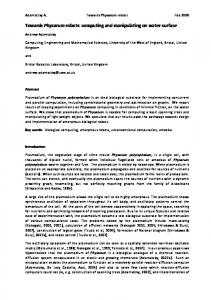
3. Hierarchical image matching on Splash 2 Figure 1 illustrates a complete pyramid generation and tracking system that has been implemented on Splash 2. This design utilizes all 17 FPGAs on one Splash processor board, which are designated X0 to X16 and are colloquially referred to as PEs. The main duty of X0 is to accept and format input pixels, and to control crossbar interconnections between the PEs. The upper half of the figure represents the portion of the system that generates Gaussian pyramids, and the lower half performs tracking using those image pyramids. This design generates 5-level Gaussian pyramids at a rate of 30 per second. It is also possible to use a single 4-chip recirculating block to generate 5-level pyramids at a rate of 15 per second. Details on pyramid formation can be found in [Abbo95]. The lower half of Figure 1 represents the tracking system, which is subdivided into four separate stages. For the system discussed here, only levels 256 × 256 and smaller are processed, performing the tracking operation at a rate of 30 images per second. A second design, which is not discussed here in detail, performs tracking also using the full-resolution 512 × 512 images, but at the slower rate of 15 images per second. The first stage of the tracking system, comprising X9 only, receives each incoming pyramid from X4 and X8. It passes the 256 × 256 image to stage 4, and simultaneously sends the lower-resolution levels to stage 2. Stage 2, consisting of PEs X10-X11, stores the pyramids in its memory and furnishes image data to stage 3 for processing. It sends both reference-window pixels and search-window pixels to stage 3 as needed. Stage 3 (X12-X13) performs the SAD computation and transfers the row/column locations of the winning matches to stages 2 and 4. Stage 4 (X14-X15) computes the final target position within the 256 × 256 image, highlights the target location, and transfers the resulting image to X16 for final formatting and display. Because image matching begins at the coarsest level, tracking computations do not commence until a complete pyramid has been received. To accommodate this, 2 chips each within stages 2 and 4 store and process alternate image pyramids in the sequence. Using the convention that image frames are numbered beginning with 0 at system initialization, the first chip (X10 and X14) stores all odd-numbered pyramids while the second chip (X11 and X15) stores all even-numbered pyramids. As one pyramid is being stored, the other PE in these blocks facilitates image matching on the
other pyramid. The actual matching computations performed in stage 3 are compute-intensive, and utilize two FPGA chips in an SIMD mode to achieve real-time operation. The first chip (X12) performs computations for 16 × 16 image windows that begin on even columns, and the second chip (X13) simultaneously performs the same computations for windows that begin on odd columns. This is a form of SIMD computing because the same operations occur on different PEs, but with different data.
4. Results This system has been tested at full speed on Splash 2, and at slower speeds to aid in design verification. Sample results are shown in Figure 3, and are identical to results obtained using a software implementation on a Sun workstation. A timing analysis, as performed by the Xilinx design tools, indicates a worstcase maximum clock frequency for the FPGAs of the tracking stages of 8.7 MHz for the XC4010-5 parts. This is higher than the minimum 7.86 MHz clock frequency required to transfer 512 × 512 images at a rate of 30 images/second. The current Splash implementation operates at a clock frequency of 10 MHz, however, and the design of two of the chips will need to be improved before correct operation can be guaranteed at this frequency. However, no speed-related problems were observed at this higher clock frequency.
5. Conclusion This paper has described the design and implementation of a real-time visual tracking system on the Splash 2 architecture. The use of Splash 2 (or other CCMs) for such image-based tasks is attractive because dedicated hardware is not needed, although the system delivers performance approaching fully custom hardware (such as that described in [Burt88, vand92, Zhan93]). This is possible because the fine-grain configurability of the system permits designs that utilize high-level pipelining coupled with lower-level data recirculation and SIMD-like processing. A drawback of this approach is that the designer faces a fairly steep learning curve, although this may be due largely to the limitations of current design tools. Based on the lessons learned using Splash, some newer CCMs are under development that incorporate such helpful features as a mixture of local and global memory, dual-port access to some of the memory elements, and increased I/O capability on the FPGAs. Without great difficulty, the tracking system can be scaled to work for pyramids constructed from images of very large sizes. For larger images, the number of chips used for correlation can be increased to reduce the number of processing cycles for this operation. For instance, correlation has been partitioned such that all search blocks beginning on even columns of the search window are processed by one chip while simultaneously, all the search blocks beginning on odd columns are processed by another pyramid. This can be extended to four chips by letting a pair of chips process all search blocks that begin on even rows and another pair of chips process all search blocks that begin on odd rows so that the time taken for performing correlation will be reduced by half.
References [Abbo94] A. L. Abbott, P. M. Athanas, L. Chen, and R. L. Elliott: "Finding Lines and Building Pyramids with Splash 2," Proceedings: IEEE Workshop on FPGAs for Custom Computing Machines, Napa, CA, April 1994, pp. 155-163. [Atha95] P. M. Athanas and A. L. Abbott: "Real-Time Image Processing on a Custom Computing Platform," IEEE Computer, vol. 28, no. 2, Feb. 1995, pp. 16-25. [Burt83] P. J. Burt and E. H. Adelson: "The Laplacian Pyramid as a Compact Image Code," IEEE Transactions on Communications, vol. COM-31, pp. 532-540, 1983. [Hall76] E. L. Hall, J. Rouge, and R. Y. Wong: "Hierarchical Search for Image Matching," Proceedings: IEEE Conference on Decision and Control, Dec. 1976, pp. 791-796. [Isel95] C. Iseli and E. Sanchez, "Spyder, a SURE, SUperscalar and REconfigurable, Processor," Journal of Supercomputing, vol. 9, pp. 231-252, 1995. [Pudi96] B. Pudipeddi: "Implementation of Coarse-to-Fine Visual Tracking on a Custom Computing Machine," M. S. Thesis, Bradley Dept. of Electrical Engineering, Virginia Tech, 1996. [Tani78] S. L. Tanimoto, "A Comparison of Some Image Searching Methods," Proceedings: IEEE Conference on Pattern Recognition and Image Processing, June 1978, pp. 280-286. [vand92] G. S. van der Wal and P. J. Burt, "A VLSI Pyramid Chip for Multiresolution Image Analysis," International Journal of Computer Vision, vol. 8, no. 3, 1992, pp. 177-189. [Zhan93] Z.-Y. Zhang and B.-Z. Yuan, "Multiresolution Target Detection and Tracking through a parallel Coarse-to-Fine Search Approach," Proceedings: IEEE TENCON '93, Beijing, P. R. China, 1993, pp. 1198-1202. Filter by Gx
Input image X0
Filter by Gy
Store
Filter by Gx
Filter by Gy
Combine
X1
X2
X3
X4
X5
X6
X7
X8
X16
X15
X14
X13
X12
X11
X10
X9
Output image
Format output
Tracking stage 4
Tracking stage 3
Tracking stage 2
Tracking stage 1
Fig. 1. Block diagram of a tracking system on Splash 2. Chips X0 - X16 represent the XC4010 FPGAs of one processor board, and they are connected as a linear array. The other connections are made though a crossbar switch. The top half of the figure is the Gaussian pyramid generator, and the bottom half performs image matching.
Fig. 2. Four levels of a Gaussian pyramid. These were computed by Splash 2 from a 512 × 512 image which is not shown. The image sizes here are 256 × 256, 128 × 128, 64 × 64, and finally 32 × 32, which serves as the coarsest level in this implementation.
Fig. 3. Three frames of a test image sequence, in which a taxi is seen turning a corner at an intersection. The target to be tracked was taken from the center of the first frame (not shown). White rectangles of size 16×16 represent the best matches found in each image, relative to the target's appearance in the previous image.