7-7 A Consistent Dynamic MOSFET Model for Low-Voltage Applications G. Schrom, A. Stach, and S. Selberherr Institute for Microelectronics, TU Vienna, Gusshausstrasse 27-29, A-1040 Vienna, Austria Phone +43/1/58801-3750, FAX +43/1/5059224, e-mail
[email protected] The development towards lower voltages and even ultra-low-power (ULP) technologies [l,2, 31 makes ever higher demands on compact device model accuracy. We present a new approach to dynamic MOSFET modeling, which is especially suited for the simulation of low-voltage mixed analog digital circuits. The model is based on terminal charges and conductive currents which are determined from transient current/voltage data which can be easily obtained through measurement or simulation of the devices.
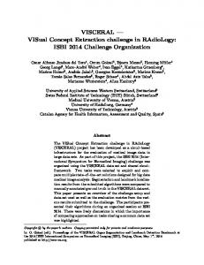
Model Function and Simulation Environment. The model function is based on a physically motivated interpolation of the terminal currents and charges of the device. The interpolation also supplies the derivatives, i.e., the conductance and capacitance matrices of the device. These data are directly interfaced to a new circuit simulator, MINISIM [4], which uses charge conservative capacitance modeling. The interpolation uses piecewise polynomial and/or exponential splines to account for the physical nature of the quantities (especially the exponential dependence of the currents). This approach rules out common problems like, e.g., discrepancies between the AC-model conductance parameters and the derivatives of the DC-model currents. Device Characterization. The input data to the model can be obtained either by measurements or by process and device simulations. For this work we used VISTA with MINIMOS [5] to obtain the data by coupled process and device simulation. All conductive currents can be obtained directly from DC measurements. The charge data are computed from transient simulations as shown in Fig. 1 for the case of a two-pole: the device is modeled as a quasi static black box which is equivalent to a nonlinear conductance parallel to a nonlinear capacitance C(w) = dq/dw. Applying a symmetrical trapezoidal voltage v ( t ) to the device will result in a current i ( t ) which can be separated into a conductive current i c o n d ( w ) = (i(tl(v)) i(tl(v)))/2 and a capacitive current i c a p ( v )= ( i ( t l ( w ) )- i(tl(v)))/2 which relates to the charge as i c a p ( w ) = dq/dt = (dq/dw). ( d v / d t ) . Thus, the charge can be determined as q(v) = qo icap(v)dw.The charge offset qo can be determined from q(0) = 0. In the case of the MOSFET we have a three-pole (assuming the source always grounded), one of the other terminals is ramped, and the currents at all terminals (including the ramped one) are measured and subsequently converted to i/q-data. To obtain a complete field of charge data, including the charge offset, a series of transient measurements/simulations is required as shown in Fig. 2. According to the desired ranges and step sizes of vbs, V,, , and Vds, one transient in 'Vbs-direction', n transients in 'V,,-direction', and n x m transients in 'Vd,-direction' are measured or simulated. Of these, the first 1 + n are required for the charge offset computation. The steepness of the ramp determines the accuracy of the charge data and the influence of non-quasi-stat.ic effects accordingly. Both can be verified with single transient measurements, using the i/q-extraction software (cf. Fig. 3). For the simulation with MINIMOS the input decks are generated automatically according to the range settings which also control the computation of the current/charge data.
+
+ suu12
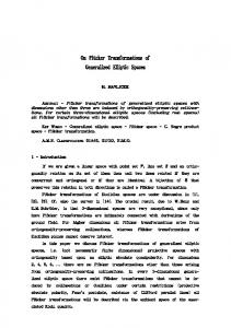
Applications. Example applications are shown in Figs. 4-6. Fig. 4 shows the simulated switching transients of an RS flip-flop designed in a 0.5V ultra-low-power technology [3]. The same technology can be used to build OPAMPs, operating at even lower supply voltages. Due to its inherent accuracy, our new model could show the feasibility of ultra-low-power OPAMPs working at supply voltages well below 1V. Fig. 6 shows the simulated large-signal step response of the two-stage OPAMP shown in Fig. 5 operating as a follower at VDD= 0.4V. The frequency compensation is accomplished by wider output transistors (M7, M8), utilizing their internal capacitances rather than a separate capacitor (Cl). The OPAMP is biased for medium speed, consuming a total of 4.0pW. Conclusion. Our new low-voltage MOSFET modeling approach, together with the supporting software enables the accurate simulation of modern mixed analog digital circuits directly from measured or simulated data. This can be profitably used for process evaluation and optimization on the circuit level without intermediate parameter fitting. [1] J.B. Burr. Stanford Ultra Low Power CMOS. In Symposium Record, Hot Chips V , pp. 7.4.1-7.4.12, 1993. [2] D. Liu and Ch. Svensson. Trading Speed for Low Power by Choice of Supply and Threshold Voltages. IEEE J.Solid-State Circuits, 28( 1):lO-17, 1993. 131 G. Schrom, D. Liu, Ch. Pichler, Ch. Sverisson, and S. Selberherr. Analysis of Ultra-Low-Power CMOS with Process and Device Simulation. In C. Hill and P. Ashburn, editors, 24th European Solid State Device Research Conference - ESSDERC'94, pp. 679-682, Gif-sur-Yvette Cedex, France, 1994. Editions Frontieres. [4] A. Stach. Simulation von MOSFET-Schaltungen. Diplomarbeit, Technische Universitat Wien, 1995. [5] Ch. Pichler and S. Selberherr. Process Flow Representation within the VISTA Framework. In S. Selberherr, H . Stippel, and E. Strasser, editors, Simulation of Semiconductor Devices a n d Processes, volume 5, pp. 2528. Springer, 1993.
177
Vd
I
tlj
I
i
I l
I l
:
t21
I I
;
c
i,cond
v
i,cap
I
I
1
I
t
Figure 2: Transient MOSFET simulations / measurements
Figure 1: Quasi static black-box model of a two-pole
4.0
I
I
I
I
transient -
I
I
I
I
i
I
3.5
-
3.0
-
_________-----.
0.5 n
L 0.4 0.3 -9P 0.2 UY
+a
2.5
-20
-
2.0
0.1
'
0.0
1.5 I -2.0 -1.5 -1.0 -0.5 0.0 0.5 I
I
I
I
I
I
I
I
-0.1
0.0
1.0 1.5 2.0
1
I
I
I
1
2.0
4.0
6.0
8.0
10.0
time [ns]
gate voltage [VI
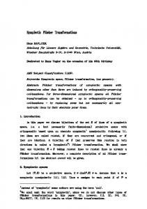
Figure 4: Switching transients of an ULP RS flip(VDD= 0.5V) flop
Figure 3: Gate capacitance of an ULP n-channel MOSFET (Vds = &., = 0 ) . - - - : computed through accurate gate charge integration using MINIMOS's 'GCHC' option. -: transient method (tP = 3ns).
L
0.25
c
+in out (a) -----
,-. ;1-1
out (b)
......
2
2
r,
0.20
>
-2
2
0.15
L
I
I
200
300
400
0.10
I
I
1
500 600 700 time [ns]
I 1 800 900
Figure 6: Large-signal step response of an ULP VDD= 0.4V OPAMP operating as a follower at with (a) CL = OpF and (b) CL = 1pF.
Figure 5: ULP OPAMP with a self-compensating output stage
Acknowledgment. Our work is significantly supported by Austria Mikro Systeme AG, Unterpremstatten, Austria; Christian Doppler Gesellschaft, Vienna, Austria; and Siemens Corporation at Munich, Germany. 178