This paper presents how a continuous mission verification process similar than in soft ... alongside the Concurrent Engineering process helps to mature both, the ...
A Continuous Verification Process in Concurrent Engineering Volker Schaus∗, Michael Tiede†, Philipp M. Fischer†, Daniel L¨ udtke†, and Andreas Gerndt‡ German Aerospace Center, Simulation and Software Technology, 38108 Braunschweig, Germany
This paper presents how a continuous mission verification process similar than in software engineering can be applied in early spacecraft design and Concurrent Engineering. Following the Model-based Systems Engineering paradigm, all engineers contribute to one single centralized data model of the system. The data model is enriched with some extra information to create an executable representation of the spacecraft and its mission. That executable scenario allows for verifications against requirements that have been formalized using appropriate techniques from the field of formal verification. The paper focuses on a current approach of integrating this verification mechanism into our Concurrent Engineering environment. In an example study, we explain how basic mission requirements are created at the beginning of the spacecraft design. After each iteration and change, the integrated verification will be executed. This instantly highlights the effects of the modification and points out potential problems in the design. Using the continuous verification process alongside the Concurrent Engineering process helps to mature both, the requirements and the design itself.
I.
Introduction
pacecraft are commonly considered to be complex systems. Verification is an inevitable part of space S mission design and the projects use practices like the V-model where verification is an essential principal. From a Systems Engineering point of view, it is important to know as much as possible about the system as 1
early as possible. The decisions made at the beginning of the projects define up to 85% of the overall cost of the project.2 This frontloading of information requires that verification is also included right from the start. Concurrent Engineering (CE) has evolved into a successful methodology to elaborate early spacecraft system designs and decide on the feasibility of a space mission. The CE process follows the principle of bringing stakeholders together in one room at the same time, thus increasing communication and joint understanding of the design on system level. Within some weeks only, the engineers can pin down the baseline requirements as well as delivering a fundamental design covering aspects like the mass summary, power consumption and costs.3 However, in this agile process with many design iterations, it remains difficult to track changes. In particular, it is difficult to see the implications on the overall behavior of the system caused by changes to one subsystem. Therefore, it is desirable to have a verification process that runs after each design change and analyzes the spacecraft design with respect to its mission goals. Other disciplines, for example software engineering, experience similar difficulties. Some of the open source projects or large enterprise software products are considerably complex and hundreds of engineers and computer scientists contribute to the final software system. The community has addressed that issue and implemented a process called continuous integration. It is based on the idea that every change to the software system is fully integrated and automatically tested against specifications. This demands that every engineer is not only delivering productive source code, but tests for it as well. The continuous integration server reacts on every change on the source code and rebuilds the software. It executes the tests and informs all engineers about the results, if tests are failing or not. The automated execution of the builds and tests ∗ Research
Scientist, New Member Scientist ‡ Head of Department Software for Space Systems and Interactive Visualization † Research
1 of 11 American Institute of Aeronautics and Astronautics
ensures that the quality is kept on a high level. This frees engineering time spent on repetitive and dull tasks and allows the engineers to focus on the design rather than on manual verification.4 The motivation for the work presented in this paper grew even more by participating in one week CE studies.5 We noticed that verification is addressed mainly on subsystem level. Many domain experts have adequate means to verify the part of the design which they are responsible for, e.g. doing a structural or a thermal analysis of the satellite. However, the evaluation of the design on system level remains difficult, especially considering a dynamic behavior. The systems engineer has little means to analyze the complex interactions and contributions of individual designs with respect to the overall mission objectives. One common way of doing verification of the complete system is setting up a dynamic simulation, an approach currently carried out in later design phases when detailed models of the subsystem are available. ESA tries to involve a simulation expert already during their CE activity using a tailored simulation environment.6,7 Our approach postulates to add a verification expert to the CE core team. The purpose of this new role is set up an executable verification model which takes advantage of the information of the central system model. This verification model covers the functional and temporal behavior the spacecraft and respects mission objectives and constraints. A special mission checking framework analyzes the design after each design change. With this, the verification expert produces quick results which can be directly used in the following design session. The remainder of the paper is organized as follows: The next section gives an overview of the Systems Engineering methodology in spacecraft design as it is currently used at the German Aerospace Center. Section III explains the technologies behind the mission verification framework. Section IV introduces an example space mission and explains in detail how mission verification can be used in the Concurrent Engineering process. This section also includes a short evaluation of the characteristic parameters for the mission verification. Then, the paper concludes and mentions some future ideas.
II.
Model-based Systems Engineering applied in Concurrent Engineering
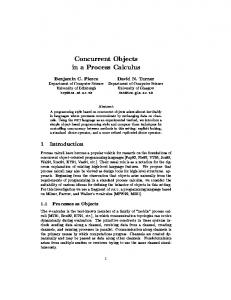
The Virtual Satellite initiative of the German Aerospace Center (DLR) promotes Model-based Systems Engineering (MBSE) methodologies starting at the very beginning of space mission design. In this project we developed a software to support the space mission design process. The software has reached a productive state and was used successfully in several CE studies. One field of application is DLR’s Concurrent Engineering Facility at the Institute for Space Systems. Here, the various stakeholders come together for initial mission designs and feasibility studies. CE is a structured design process that has some important characteristics. Typically, the design is evolving fast and since all involved personnel is available at the same time, quick iterations are common. At the beginning of the design the uncertainty is quite high, because many values are based on estimations or assumption. In order to compensate for the uncertainty, the design team applies margins of up to 30% to their values. The Virtual Satellite software fully covers the Concurrent Engineering work methodology as shown in Figure 1. All members of the design team work on a central repository, thus following the model-based paradigm of having a system model as single point of truth. They commit their design information through a special client and make it available for others. In return, they can receive the updates of others and use it as input for their own design. The software has a role management to assign certain people to their responsibility. This assures that the team members can only modify a part of the design, typically a subsystem like power or thermal. On the other hand, everyone can see the designs of others. This increases transparency and makes it easy for the team leader or systems engineer to monitor the progress of the study. The Virtual Satellite is based on a flexible and extensible data model covering many required features of the CE design. The data model allows child-parent relations to define a hierarchy and a (functional) decomposition of the design. Further, it provides means to define subsystems or components with parameters and calculations. The data model also offers the possibility to introduce so called modes of operation. They are used to split the mission in time periods where certain activities are performed. For instance, an Earth observation mission would have a camera mode, where certain equipment is turned on and requires a certain amount of energy. The power consumptions can vary dependent on the modes. Defining modes is one task of CE and mode dependent parameters are a first attempt to describe dynamic behavior of the system. The domain experts are usually responsible for one subsystem. They come up with a design, enter their values and calculations and share the information with the team. They are also doing subsystem analysis and evaluation which is often performed in established domain specific tools. The systems engineer has
2 of 11 American Institute of Aeronautics and Astronautics
VirSat
VirSat
Systems engineer System model Central repository
Domain experts
Customer VirSat
VirSat
Verification expert
Team leader
Figure 1. Concurrent Engineering with the software Virtual Satellite
different tasks, e.g. monitoring the mass and power budget of the spacecraft. The two other important actors are the team leader and the customer. The team leader guides the study, triggers and assigns tasks to certain people, raises questions, and generally has the overview. The customer should be involved as much as possible so that his needs are understood and hopefully satisfied in the end.
III.
Mission verification
We instigated the work on verification for Concurrent Engineering over a year ago. We first looked at formal verification techniques used in software and hardware designs. We particularly decided to use model checkers because they potentially do a fully automated verification of a system against a given specification. In a first paper we examined the information which is typically available at the beginning of a spacecraft design and transferred it into a state machine. The state machine was used as input for an existing model checker. We found that this is generally possible, but experienced the state explosion problem very quickly. An exhaustive coverage of the state space becomes impossible because of memory and computational limits. This is especially true for the nature of a space missions where state transitions are often calculated by data and time continuous simulation models.8 One idea to avoid the state explosion was to replace the model checker and use informed search algorithms instead. The advantage of this approach is that the search algorithms do not have to examine all possible state transitions. Instead they are driven by a cost function and try to find a way (or the best way) through the state space to reach the mission goal. It is also possible to define constraints, e.g. the physical size of the on-board memory or discharging the battery below the safety criteria which potentially harms the spacecraft. The search algorithm treats these as hard limits and eliminates any state transitions that violate such a constraint. This reduces the state space, too. We implemented several algorithms, most importantly the A* algorithm and looked at heuristics to define the cost functions. The results were promising: the computations were fast and we were able to connect simulation models directly to the state machine to increase the level of detail. Another important aspect is that most of this work was directly implemented as a new part of the Virtual Satellite software, a part which is now called mission checking framework.9,10 The workflow and integration in the CE process of the verification framework is explained in Figure 2. The system model as it is defined by the CE team is the input for the framework. It is transformed into an executable state machine model. The verification expert can edit the definition of the state machine model with a textual editor. Here, it is possible to select different search algorithm or connect simulation models 3 of 11 American Institute of Aeronautics and Astronautics
Mission checking framework
System model
Verification model
Search algorithms
Evaluation of results
g. ..
Verification expert
Algorithm finds state space transitions to reach mission goals
Se ar ch in
Domain specific language editor
Simulation models
Figure 2. Workflow of the verification with the mission checking framework in Concurrent Engineering
to the state machine. The editor is based on a domain specific language, a spacecraft description language in this case, which provide user friendly features such as keyword completion and syntax highlighting. Once the scenario of the mission is fully described, the verification expert can start a run of the search algorithm. When the algorithm is successful, it gives the sequence of state transitions leading to a result. In the opposite case, when it cannot find a way through the state space that reaches the goal, the software notifies the user.
IV. IV.A.
Example: A technology demonstrator mission
Maturing the requirements
As an example to demonstrate the possibilities of continuous verification in CE, we use a scenario which is derived from the TET-1 space mission, a German technology demonstration microsatellite launched in 2012. The main goal of this mission is to provide a low cost platform for on orbit validation of new space technology. TET-1 carries a total of eleven experiments as payloads.11 On the basis of the TET-1 mission, we derive a simplified example, yet considering realistic design information and requirements from the original mission. The satellite shall be on a low Earth, sun synchronous orbit at a high inclination of 97.5◦ , a period of 95 minutes and an altitude of 520 km. Instead of considering all eleven experiments we use only three in our simplified scenario namely an infra-red camera for detecting fires on Earth, a GPS experiment, and a small satellite propulsion system. All experiments gather science data and the overall mission objective is to gather 10 Gigabytes of experiment data and the mission should not take longer than one year. These are typical initial requirements that are used as a starting point for a first design in a CE process. The team then decides for certain concepts which are promising to fulfill the mission goal. In our example we are interested to have the experiment data back on the ground, so we need a concept to retrieve it. Rather than doing a re-entry mission, let us assume we decide for first storing the data on an on-board mass memory and then downlink it to the ground. This triggers the data handling expert who will provide first estimates for downlink bandwidth and mass memory size. At the same time the experiment specialists come up with the amount of data their experiments produce in a certain period of time and how much power they will use. The power domain considers all on-board consumers and lays out a battery and solar cells to generate power. From a system level point of view we define certain modes of operation for our mission. We assume that the experiments run separately so they are each represented by an individual mode. Additionally, we define separate modes for charging the satellite, downlinking the data and idle time. Each mode is associated with a duration and this allows us to define parameters changes over time, thus adding information about the dynamic behavior of the system. Table 1 gives an overview of the requirements and the design after the first CE iteration. The members of the design team enter all this information into the central system model. The team leader and systems engineer monitor the design and assure that all necessary design information
4 of 11 American Institute of Aeronautics and Astronautics
appears in the central repository. Table 1. Requirements subsystem constraints as initial input for the mission verification framework
Requirement/Constraint Mission objective Orbit Mass memory size Downlink bandwidth Battery capacity Modes of operation
Value 10 GB of data in one year Low Earth, sun synchronous orbit* 512 MB* 2.2Mbit/s* 4320W h = 240Ah · 18V * 6 modes (three experiment modes, charge, downlink and idle)
* Actual
value of the TET-1 mission: https://directory.eoportal.org/web/eoportal/satellite-missions/t/tet-1 [last accessed: 08/06/2013]
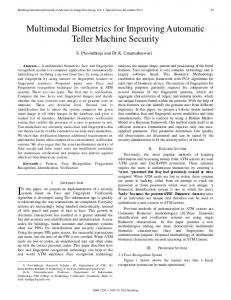
After this first iteration, the mission verification expert can start setting up the executable state machine model. We transform the system model in an input file for the verification framework. This means, we define state variables, initial values, constraints, goals and the state changes in accordance with the information contained in the system model. Of course, not all information is directly usable or available at this early stage. For instance, so far we have no information about contact times to a ground station. Therefore, it is unknown how much data we can actually send to the ground. We overcome this lack of information by using assumptions or simplifications and integrate them directly in the state machine definition. In this particular case, the simplification is, we allow downlink at any time and assume a very low bandwidth. Now we run the mission checker. The search algorithm tries to find a sequence of state changes that fulfill our goal of downlinking 10 Gigabyte of data in one year. In case it does, it returns a list of all state changes including the state parameter changes leading to the successful mission for further analysis. Otherwise it states that it can not find a solution for the given mission scenario. The result of the first run is depicted in Figure 3 on the left hand side. Here, the amount of data is plotted over the mission time. We see that the search algorithm found a sequence of state transitions which reaches the goal; the required 10 Gigabytes of data are downlinked in 16 days. But only the camera experiment was selected and produced data. The other two experiments were not executed and produced no data in result. The mission verification expert takes the results and discusses them with the design team and initiates the next iteration. Now, considering the requirements, the graphs make sense, because the only statement for mission success was the amount of downlinked data in one year. We did not state the requirement that each experiment has to run at least once during the mission or give individual data requirements for each payload. Let us consider the team leader decides to define individual goals for each experiment. He assigns the task to the experiment specialists and they come up with values for required amount of data for each experiment. They commit their numbers to the system model and they are added as goals to the mission verification framework which analyzes the modified mission directly. The result of the second mission verification run is given in Figure 3 on the right hand side. We are still acquiring 10 Gigabytes of data overall, and additionally all three experiments are now scheduled one after the other. The camera and the propulsion experiment reach their required amount of data and are not executed any more. The GPS experiment is collecting the rest of the data until the overall 10 Gigabytes are reached. The mission time has increased to 42 days. This first evolution of the design shows how the result of the verification model can help to mature the requirements. In this particular case we found a deficiency in our requirements. We defined individual required data for the three on-board experiments as additional goals that more precisely describe what we want to achieve in our mission. The result can directly be seen by analyzing the state transitions. IV.B.
Increasing the level of detail with simulation models
So far, the model still allows selecting the downlink mode at all times. This is not possible in reality of course, because we can only send data down to the ground if we have contact to a ground station. In a first refinement we include a simple communication simulation to our state machine. From previous missions we know that on similar orbits we have an average of one hour connection to the ground per day. This information is put into a very simple simulation model which, based on the mission time, sets a flag indicating whether there is 5 of 11 American Institute of Aeronautics and Astronautics
Goal
8
6 4 2 0
Goal
10 Amount of data [GB]
Amount of data [GB]
10
8 Downlinked
6
Exp. Camera 4
Exp. GPS
2
Exp. Propulsion
0
2
4 6 8 10 12 Mission Time [days]
14
10 20 30 Mission time [days]
40
Figure 3. Results of the first and second run of the mission verification showing the improvement of adding goals for the three on-board experiments
contact or not. In consequence, the mission checker can only select the downlink mode if the downlink flag is set. This simulation model is called in a special section of the state machine description. The results of this refined mission with a simulation model are depicted in Figure 4 in the left column. As before, we can see the collected amount of data of the experiments and the downlinked data in the first plot. Additionally, we are also plotting the development of the mass memory capacity utilization. Starting at the top left, we see that we can still reach our goal. The behavior is similar to the one we observed in the previous run. The camera experiment is selected first and produced the majority of the downlinked data. The other two experiments are executed thereafter. The mission time is at 82 days which is almost twice as long as in the last run. Looking closer at the graph we see a step-like development where over a period of a couple of days no downlink is possible. This is also clearly resembled in the second graph on the left hand side showing the utilization of the on-board mass memory. The mass memory is quickly filled with experiment data. Then, there is a recurring pattern of downlinking the data and running the camera experiment. In the ground station contact simulation model we allowed downlink every day, but the period of the pattern is longer than one day. The reason for this is the step sizes of our simulation model and the state durations of the state machine that represents the duration of the modes of operation. In other words, when the duration of a mode is longer than the one hour downlink window, we simply miss the option of sending data to the ground. So here, we are running into step-size problems as they are common in simulations. The general rule that the step-size has to match the resolution of the underlying problem applies here as well. In the next step, we adjust the step size of our state duration and the simulation model. We set it to 1.44 minutes (1/1000 of a day). Also, we improve the downlink connection model. We replace the simple model of setting the downlink flag with a SGP4§ orbit propagator and a ground station model which checks if a downlink is possible based on the position of the satellite. The results of detailed analysis are depicted in the right column of Figure 4. We clearly see the effect of the smaller step size. We have frequent contact to the ground. The propulsion experiment is starting earlier and is scheduled alternating with the camera experiment. In comparison to the previous results, the time to reach the mission objective dropped to 64 days. IV.C.
Identifying and exploring trade-off scenarios
In the second graph on the right hand side of Figure 4, we see that mass memory is used to capacity over a very long period of the mission. The mission verification expert can use this information to point out potential trade off scenarios for the next CE session. In this particular case he could propose to the team to look into using a larger on-board mass memory system. This is a task for data handling to check for other available equipment, or in case a totally new component has to be developed, how much does it cost. The mission verification expert can easily adjust the model, e.g. double the size of the mass memory, run the verification and look at the results again. We could also explore in another direction. We noticed that the mass memory is very full: data is available, but it cannot be transmitted to the ground. So we might want to explore the effect of adding another ground station to our scenario. Again, we do this in the similar fashion § The SGP4 algorithm calculates the orbital state vector for low Earth orbits and uses simplified perturbation models for The Earth’s shape, atmospheric drag, and gravitation effects from Sun and Moon.
6 of 11 American Institute of Aeronautics and Astronautics
Goal
8 6 4 2
8
Downlinked
6
Exp. Camera
4
Exp. GPS
2
Exp. Propulsion
0
0 0
10
20 30 40 50 60 Mission time [days]
70
0
80
500
Amount of data [MB]
Amount of data [MB]
Goal
10 Amount of data [GB]
Amount of data [GB]
10
400 300 200 100 0
10
20 30 40 50 Mission time [days]
60
500 400 300 Mass memory capacity utilization
200 100 0
0
10
20 30 40 50 60 Mission time [days]
70
80
0
10
20 30 40 50 Mission time [days]
60
Figure 4. Results of the mission verification with simulation models; simple communication model on the left and orbit propagation model on the right hand side. The first row shows the accumulated data of each on-board experiment and the total amount of downlinked data. The second row shows the capacity utilization of the mass memory on the spacecraft.
as before when we increased the mass memory. We add a second and potentially a third and fourth ground station to our model, run the mission verification and look at the results. Using more ground stations also means higher cost for the mission. Last but not least, the payload specialist for the camera system has to look into the possibilities of reducing the amount of data that the camera is producing. Maybe pre-processing is an option, but it adds complexity and another computer to the satellite, therefore has other implications on the design. The mission verification framework makes it very easy to explore in multiple directions. We can set up different scenarios to explore the trade space quickly and then use it to make informed decisions in the design process. The result of our analysis for the example was that the increase of the mass memory has only a small positive effect. It reduced the mission time by some days, yet the mass memory reached its capacity of now one Gigabyte very quickly and stayed high as long as the camera experiment was active. Adding more ground stations had the desired effect of significantly cutting down the mission time. Three well distributed ground stations allowed us to downlink the data in just 24 days. The detailed graphs of this trade exploration are given in the Appendix. IV.D.
Applicability in Concurrent Engineering
We found that the performance of the mission verification part of Virtual Satellite is well suited for the Concurrent Engineering process. The presented example shows the flexibility of the approach which is necessary for the early stages of a mission design. It is possible to quickly adapt the input for the mission checking framework and to give feedback to the design team by evaluating the results. The framework is also easily extensible. Extension points offer a fast way to connect new simulation models. New language elements for describing the satellites state machine can be added during an ongoing Concurrent Engineering session if required. In Table 2 we present some characteristic parameters of the state machine description of the above example to give an idea of the complexity and size of the problem. The first column shows the values of the initial design of the technology demonstrator mission. This was just a state machine with no simulation model attached. The second column is the simple ground communication simulation model. The third 7 of 11 American Institute of Aeronautics and Astronautics
Table 2. Characteristics of the mission verification runs
Initial design: No simulation State variables Modes of operations Step size of state transition Step size of simulation Evaluated state changes Computation time
7 6 0.1 422 0.05s
First refinement: Simple ground station communication simulation 8 6 0.01 0.01 1466 1.00s
Second refinement: Orbit propagation with ground station positions 14 6 0.001 0.001 26281 11.97s
column presents the most complex set up in the example, the orbit propagation model in conjunction with ground station locations. At first, we are looking at the number of state variables, which increases as we describe the space mission in more detail. At the beginning, we defined variables for the amount of data of the three experiments and the downlinked data. We also have a parameter for the mission time, the mass memory capacity and the battery charge. The number of state variables doubles as we add more details. For instance, the orbit propagation algorithm needs to store the position and velocity of the satellite as state parameters. The modes of operation, respectively the number of states remains constant throughout the example. The defined states are: Idle, Charge, Downlink, and one state for each experiment on board. Further, the table shows the minimal step size, the number of state transitions needed to fulfill the mission objective and the computational time needed. The step size is relatively long in the initial design, therefore the number of state transitions is quite low and the computational time is short. As the level of detail increases and we connect the simulation models, the number of state transition and computation time both grow. The worst case took just under twelve seconds to find a matching sequence of state transitions which is still relatively short and can very well be used in Concurrent Engineering. All these models were executed on a standard notebook with a Core i7 processor. The available memory was limited to one Gigabyte by the size of the Java Virtual Machine. Of course, the presented example does not have the same complexity and number of parameters as a typical Concurrent Engineering spacecraft study. However, the results are promising that this kind of mission verification can successfully support the Concurrent Engineering process.
V.
Conclusion
In this paper, we propose to add a verification expert as a separate domain to the Concurrent Engineering core team in order to check the feasibility of the planned mission. The integrated mission checking framework of the software Virtual Satellite takes the information of the system model directly and turns it into a state machine model representing the dynamic behavior and the mission goals. The verification expert analyzes this model with informed search algorithms and uses the results as direct feedback for the design team. The example of space mission explains in detail how this feedback matures requirements, increases the level of detail of the design and supports fast trade-off studies. In the future, we plan to do a field test of the framework in an actual CE study to get first hand user experiences and apply it to a large scale study. This helps to further enhance the implementation and improve the usability. We would also like to integrate the analysis of the results into Virtual Satellite which is currently done in external tools. The driving element of the mission checking process is the cost function of the search algorithm. Here, further research is necessary to find heuristics for defining the cost functions for certain algorithms.
8 of 11 American Institute of Aeronautics and Astronautics
Appendix Figure 5 gives the results of the two modifications that we explained in IV to explore the trade space. The plots on the left hand side show the mission with an increased mass memory (1024 MB). On the right hand side are the resulting missions with additional ground stations. Goal
8 6 4 2 0
8 Downlinked 6
Exp. Camera
4
Exp. GPS
2
Exp. Propulsion
0 0
10
20 30 40 50 Mission time [days]
1000
0
Amount of data [MB]
Amount of data [MB]
Goal
10 Amount of data [GB]
Amount of data [GB]
10
800 600 400 200 0
5 10 15 Mission time [days]
20
500 400 300 Mass memory capacity utilization
200 100 0
0
10
20 30 40 50 Mission time [days]
0
5 10 15 Mission time [days]
20
Figure 5. Results of the mission verification to support the trade space analysis
The following listing is a complete file of the domain specific language for the verification model. The verification expert uses this file to describe the state machine, the goals and constraints, attaches simulations models and defines which search algorithm should be used. 1 2 3 4 5 6 7 8 9 10 11 12 13 14 15 16 17 18 19 20 21 22 23 24 25 26 27 28 29 30 31 32
Describe Satellite Set Solver de . dlr . virsat . mission . modeling . c h e c k i n g a l g o r i t h m . A S t a r D e f a u l t C h e c k e r A l g o r i t h m End Describe State Parameters Parameter missionTime ; Parameter e x p e r i m e n t D a t a C a m e r a ; Parameter e x p e r i m e n t D a t a G P S ; Parameter e x p e r i m e n t D a t a P r o p u l s i o n ; Parameter massStorage ; Parameter batteryCharge ; Parameter T o t a l D o w n l i n k D a t a ; Parameter D o w n l i n k C o n n e c t i o n ; Parameter SatPositionX ; Parameter SatPositionY ; Parameter SatPositionZ ; Parameter VelocityX ; Parameter VelocityY ; Parameter VelocityZ ; End Describe Initial Parameter Values Parameter missionTime Set Value 2456268.0 ; Parameter e x p e r i m e n t D a t a C a m e r a Set Value 0.0 ; Parameter e x p e r i m e n t D a t a G P S Set Value 0.0 ; Parameter e x p e r i m e n t D a t a P r o p u l s i o n Set Value 0.0 ; Parameter massStorage Set Value 0.0 ; Parameter batteryCharge Set Value 200.0 ; Parameter T o t a l D o w n l i n k D a t a Set Value 0.0 ; Parameter D o w n l i n k C o n n e c t i o n Set Value 0.0 ; Parameter SatPositionX Set Value 0.0 ;
9 of 11 American Institute of Aeronautics and Astronautics
33 34 35 36 37 38 39 40 41 42 43 44 45 46 47 48 49 50 51 52 53 54 55 56 57 58 59 60 61 62 63 64 65 66 67 68 69 70 71 72 73 74 75 76 77 78 79 80 81 82 83 84 85 86 87 88 89 90 91 92 93 94 95 96 97 98 99 100 101 102 103 104 105 106 107 108 109 110 111 112 113 114 115
Parameter SatPositionY Set Value 0.0 ; Parameter SatPositionZ Set Value 0.0 ; End Describe Operational States State Idle ; State Downlink ; State Charge ; State Exp eriment _GPS ; State E x p e r i m e n t _ P r o p u l s i o n ; State E x p e r i m e n t _ C a m e r a ; End Describe Starting State Idle End Describe Operational State Changes State Idle Changes Parameter missionTime by 0.01 ; Changes Parameter batteryCharge by -0.1 ; End State Downlink Changes Parameter missionTime by 0.001 ; Changes Parameter batteryCharge by -0.024 ; Changes Parameter massStorage by -23.76 do not exceed 0.0 and shift inverted Value to Parameter T o t a l D o w n l i n k D a t a ; End State Charge Changes Parameter missionTime by 0.001 ; Changes Parameter batteryCharge by 0.24 do not exceed 200.0 ; End State Exp eriment _GPS Changes Parameter missionTime by 0.001 ; Changes Parameter batteryCharge by -0.024 ; Changes Parameter e x p e r i m e n t D a t a G P S by 0.2 do not exceed 1200.0 and shift effective Value to Parameter massStorage ; End State E x p e r i m e n t _ P r o p u l s i o n Changes Parameter missionTime by 0.001 ; Changes Parameter batteryCharge by -0.024 ; Changes Parameter e x p e r i m e n t D a t a P r o p u l s i o n by 0.2 do not exceed 2200.0 and shift effective Value to Parameter massStorage ; End State E x p e r i m e n t _ C a m e r a Changes Parameter missionTime by 0.001 ; Changes Parameter batteryCharge by -0.024 ; Changes Parameter e x p e r i m e n t D a t a C a m e r a by 4.0 do not exceed 7200.0 and shift effective Value to Parameter massStorage ; End End Describe Operational Constraints Constraint B a t t e r y C h a r g e C o n s t r a i n t for Parameter batteryCharge Between 40.0 And 200.0 ; Constraint m a s s S t o r a g e C o n s t r a i n t for Parameter massStorage Between 0.0 And 512.0 ; Constraint D o w n L i n k P o s s i b l e for Parameter D o w n l i n k C o n n e c t i o n Above 0.5 Accounts For State Downlink ; Constraint m i s s i o n T i m e C o n s t r a i n t for Parameter missionTime Below 2456632.0 ; // one year from start date End Describe Operational Goals Parameter T o t a l D o w n l i n k D a t a Above 10000.0 ; End Describe Simulation Modules Executing Time missionTime with StepSize 0.001 ; // 0.001 days = 1.44 min Describe Module ID de . dlr . virsat . mission . modeling . simulation . SGP4Model Initialize TLE1 with " 1 38710 U 12039 D 13217. 58194267 .00003276 00000 -0 14211 -3 0 340 " ; Initialize TLE2 with " 2 38710 97.4787 129.5105 0001914 158.0258 202.1061 15.23066867 57660 " ; End Describe Module ID de . dlr . virsat . mission . modeling . simulation . StationModel Initialize Station1 with " N 5 3 1 9 .66866 , E 1 3 4 .409178 " ; // N e u s t r e l i t z Initialize Station2 with " N 6 7 5 1 .427512 , E 2 0 5 7 .860501 " ; // Kiruna Initialize Station3 with " S 6 3 1 9 .253520 , W 5 7 5 4 .057420 " ; // O ’ Higgins End End End
10 of 11 American Institute of Aeronautics and Astronautics
References 1 European Cooperation for Space Standardization (ECSS), “Space Project Management - Project Planning and Implementation,” ECSS-M-ST-10C, 2009. 2 International Council on Systems Engineering, “Systems Engineering Handbook,” INCOSE-TP-2003-002-03.2.2, 2011. 3 Fortescue, P., Swinerd, G., and Stark, J., Spacecraft Systems Engineering, Aerospace Series, Wiley, 4th ed., 2011. 4 Fowler, M., “Continuous Integration,” http://www.martinfowler.com/articles/continuousIntegration.html, 2006, [cited 13 August 2013]. 5 Braukhane, A. and Romberg, O., “Lessons Learned from One-Week Concurrent Engineering Study Approach,” 17th International Conference on Concurrent Enterprising (ICE), 2011, pp. 1–10. 6 ESA/ESTEC, “Concurrent Design Facility Information Package,” http://esamultimedia.esa.int/docs/cdf/CDF-INFOPACK-2013v2.pdf, 2013, [cited 13 August 2013]. 7 Kalden, O., “SimVis A Concurrent Engineering Tool for Rapid Simulation Development,” Recent Advances in Space Technologies, 2007. RAST ’07. 3rd International Conference on, 2007, pp. 417–422. 8 Fischer, P. M., L¨ udtke, D., Schaus, V., Maibaum, O., and Gerndt, A., “Formal Verification in Early Mission Planning,” Simulation and EGSE facilities for Space Programmes, 2012. 9 Fischer, P. M., L¨ udtke, D., Schaus, V., and Gerndt, A., “A Formal Method for Early Spacecraft Design Verification,” IEEE Aerospace Conference, 2013, pp. 1–8. 10 Tiede, M., “Evaluation of Search Algorithms for Formal Verification of Space Missions,” Bachelor’s thesis, Ostfalia University of Applied Sciences, 2013, [in German language]. 11 Foeckersperger, S., Lattner, K., Kaiser, C., Eckert, S., B¨ arwald, W., Ritzmann, S., M¨ uhlbauer, P., Turk, M., and Willemsen, P., “The Modular German Microsatellite TET-1 for Technology On-Orbit Verification,” Proceedings of the IAA Symposium on Small Satellite Systems and Services, 2008.
11 of 11 American Institute of Aeronautics and Astronautics