Brazilian Journal of Operations & Production Management 5 Volume 4, Number 1, 2007, pp. 5-21
A control-monitoring-maintenance framework based on Petri net with objects in flexible manufacturing system. Application to a robot-driven flexible cell. Eduardo Rocha Loures Industrial and Systems Engineering Graduate Program Pontifical Catholic University of Parana Curitiba, PR, Brazil E-mail:
[email protected] Eduardo Alves Portela Santos Industrial and Systems Engineering Graduate Program Pontifical Catholic University of Parana Curitiba, PR, Brazil E-mail:
[email protected] Marco Antonio Busetti de Paula Industrial and Systems Engineering Graduate Program Pontifical Catholic University of Parana Curitiba, PR, Brazil E-mail:
[email protected]
Abstract The growing complexity of systems and the need for executing large projects have led to the development of complex flexible manufacturing systems (FMS) demanding specific control-monitoring architectures. The problem of failure occurrence tends to increase according to this complexity leading to time-consuming tasks as the localisation and repairing. The occurrence of failures during the exploitation stage can deeply modify the FMS performances or its availability. In this context, the maintenance integration into a control-monitoring system becomes an important issue, improving production time and minimizing unplanned costly breakdowns of FMS. We want to investigate the problem of triggering the maintenance, giving a useful decision support tool to evaluate the system availability since the control system’s
6
Brazilian Journal of Operations & Production Management Volume 4, Number 1, 2007, pp. 5-21
early design stage. It also results in improvement of the system’s functionality in terms of efficiency, productivity and quality. This paper proposes a control-monitoringmaintenance architecture (CMM) for FMS based on Petri nets with objects (PNO), where stochastic rates are associated to the modelling of maintenance planning. This framework is based on a modular and hierarchic model structured in CMM modules. The integration is based on a development methodology in which the maintenance aspects and policies are taken into account from the conception (modelling) stage. These efforts acts as a basis for the control architecture of a robot-driven flexible cell, connected to the Ethernet-TCP/IP. Keywords: Flexible manufacturing system, Supervision, Maintenance, Petri Nets.
INTRODUCTION The flexible manufacturing system (FMS) can be considered as a system able to produce a wide variety of products under variable production conditions. Classically, this type of system is constituted by a set of elements and devices such as workstations, transport systems, programmable logic controllers, robots, and vision systems, connected to an industrial communication network. According to the manufacturing cell dimensions’ increase, the control and supervision of its structure becomes more complex. Thus, to keep flexibility regarding its decision organization, a modular and hierarchic structure is proposed (Zamai et al., 1997). Hierarchic architectures have been subject of many works during the last decades (Gershwin et al., 1988), (Giua & DiCesare, 1994), (Srinivasan & Jafari, 1993) and represent the framework basis of recent approaches concerning the control and monitoring of FMS (Jeng & Liang, 1998), (Pascal, 2000). The demands for products with higher quality and competitive prices have led to the development of complex manufacturing systems. A consequence is that the number of failures tends to increase as well as the time required to locate and repair them. The occurrence of failures during nominal operation can deeply modify the FMS’s performance or its availability. The improvement of production times and the minimisation of unplanned costly breakdowns of manufacturing systems becomes an important issue. The potential benefits of advanced manufacturing technologies (Gouvea et al., 2000) to improve the strategic and competitive position of a firm have been shown to be closely sensitive to maintenance policies. Maintenance and its integration with control and monitoring systems enable the improvement of systems functioning, regarding availability, efficiency, productivity and quality. Thus, it is possible to implement corrective and preventive actions, making repairs and servicing easier over the process elements, as well as a better
Brazilian Journal of Operations & Production Management 7 Volume 4, Number 1, 2007, pp. 5-21
control provision of tools and repair parts. In addition, integrated to a hierarchical supervision architecture it allows a better production scheduling and planning. Then, maintenance has to be planned and scheduled; planning the execution of maintenance tasks in accordance with a production plan. Thus, it is desirable that maintenance management studies be carried out from the system conception stage. Different methods do not take maintenance into account as an isolated issue, but making it part of a supervision, control and monitoring system. Some works can be mentioned, such as the proposal of a maintenance model integrated into a supervision-control architecture performed by (Ly et al., 2000), (Berruet, 1998), the maintenance and the reconfiguration aspects in (Tang & Zhou, 2001), and the modelling and management of maintenance policies proposed by (Simeu & Sassine, 2001), (Bondavalli & Filippini, 2004), (Mouss et al., 2004), (Bérenguer et al., 2004) by means of a stochastic Petri net and its extensions. Most of these approaches focus maintenance integrated into the monitoring systems in order to support the checking of resources and planning, where real time conditions are not pointed out. In (Jeng & Liang, 1998), a SMT (supervisor - monitor - trouble-shooters) framework presents an integrated design method for supervisory control, monitoring and troubleshooting, where real time aspects are considered. Our approach looks into these two contexts (system conception stage and real time conditions in operation stage) through a CMM framework based on a development cycle methodology (DCM) proposed in (Loures & de Paula, 1999), (Santos et al., 2004). The methodology consists of a cyclic three stages development – modelling, synthesis and implementation of the CMM structure. Maintenance aspects are also taken into account from the modelling stage (equipments indicators and maintenance policies rates) to the operating stage, where appropriate monitoring techniques feeds back the maintenance policies models triggered by the CMM structure. The proposed method is structured and modular. Following a classical top-down approach, it makes it possible to build simple models, which can be validated according the supervision level, and then interconnected in order to simulate the global system’s behaviour. One of the advantages of this approach is to consider the control - monitoring maintenance functions simultaneously. Maintenance must be considered as one of the system’s main functions, linked to the control and monitoring functions. The hierarchical and modular decomposition enables the implementation of maintenance policies, limiting its effects over the global system, allowing it to preserve its availability. Another advantage is the fact that, during maintenance actions, the monitoring is kept active and guarantees a coherent intervention in the process. In this paper, the fi rst section describes the control-monitoring architecture as a basic ground for the works. Then the integration of maintenance aspects is described, leading to the proposition of the CMM architecture. The next section presents an
8
Brazilian Journal of Operations & Production Management Volume 4, Number 1, 2007, pp. 5-21
application of this architecture, which is under implementation in a real robot-driven flexible cell.
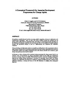
CONTROL-MONITORING-MAINTENANCE ARCHITECTURE The real time control of complex Discrete Events Systems (DES) is classically solved by structuring the control system, both hierarchical and modular, on a four-level decision organization: planning, real time scheduling/supervision, co-ordination and local control (Chaillet et al., 1997). The control functioning principle in a hierarchic context requires that only the module that has emitted a request for the lower level is able to modify it (Zamai et al., 1997). Therefore to modify a request that has been emitted, i.e., to reconsider the current control, the monitoring system must take the “request/report” sequence into consideration. Thus, a monitoring system following the control hierarchic levels and the maintenance policies needs is desirable (Ly et al., 2000). A message flow is established between the lower and the higher levels, informing maintenance parameters (e.g. cost functions, time and rate) when it is applied to the lower level. Then, the system’s unavailability may be evaluated at the higher level. Inside a CMM node a communication process (synchronization) is also observed between a reference model (e.g. equipment, workstation), the control model and the maintenance model. This allows the information system to be updated through the monitoring system and the execution of maintenance policies. Maintenance, according to (Ly et al., 2000), is defi ned as a group of technical and administrative actions, including supervision and control operations, to maintain (preventive/predictive maintenance) or re-establish (corrective maintenance) an entity to a specific state or to specific safety operating conditions (RAMS – reliability, maintainability, availability and safety) (Ly et al., 1999). Maintenance policies can be classified in four great categories (Simeu & Sassine, 2001): corrective, preventive, predictive and mixed. In all four cases, triggering a maintenance operation is a decision process based on the state (measured or estimated) of considered resources. The opportunistic maintenance (Bérenguer et al., 2004) may be also considered by modelling maintenance operations grouping procedures, which are used to take advantage of scale economies due to economic or technical dependences between components (e.g. a maintenance operation on a component triggers the maintenance of the complete line). The triggering of maintenance tasks through a continuous decision process inspired us to enrich the CM module (Zamai et al., 1997) with a maintenance module and then to defi ne the control-monitoring-maintenance (CMM) model, as shown in Figure 1.
Brazilian Journal of Operations & Production Management 9 Volume 4, Number 1, 2007, pp. 5-21
Control-Monitoring module First, let us consider the control-monitoring module. Each node is made up of the following elements: • Control Model : comprises the operation sequence to be executed, which corresponds to a specific process handling. • Reference Model: it is a process model that describes its possible states. The module’s state is verified at the moment of a control request and at the moment a process signal (report) is acknowledged. The block’s essential role is to continuously maintain the most perfect image of the real process’s state. node CMM
Operator’s Interface
UN
UN
Local Information System (LIS) 1 : follow-up 2 : failure 3 : Maintenance Policy MP 4 : knowledge 5 : Maintenance Service MS
Node CMM LIS(2) decision
diagnosis failure symptom
statistic
emergency
recovery 1 2 4
detection control model
reference model
LIS(1)
MP
maintenance model
Complementary Services
LIS
Control-monitoring module
LN
3
Node CMM
5
1
2
UN: upper node (e.g.: coordination), LN: lower node (e.g.: Local control)
maintenance module
LN
Figure 1. Control-Monitoring-Maintenance (CMM) Module
• Detection: the reference model is connected to the control model – it evolves in parallel and in real time during current operations of the process. At the moment in which the control model emits a request to the process, e.g.: starting an operation, a request is simultaneously transmitted to the reference model, which verifies the state’s consistency, and estimates a temporal window for a process event to occur (end of operation). A direct control monitoring is characterised. If the control model within the allocated temporal window receives the report issued from the process, the control and the process model evolve simultaneously. Otherwise, the reference and control models can no longer evolve. At this moment it is possible to conclude that a process fault (equipment breakdown) just occurred, based on this non-consistent event, or based on a temporal signature that characterizes a failure evolution (in a process indirect monitoring approach). Moreover, the temporal causality observation of the events allows a progressive degradation evaluation of the manufacturing functions, which lead to a deviation of the production flow (in an indirect predictive monitoring approach). In fact, process reports are temporally analysed, regardless of the orders previously sent by the control
10
Brazilian Journal of Operations & Production Management Volume 4, Number 1, 2007, pp. 5-21
part. In case of misbehaviour (a time drift on the events report), symptoms are generated and sent to the diagnostic function. The diagnosis module is thus required. Critical symptoms are also sent to error recovery in order to determine which actions have to be immediately performed to guarantee human and equipment safety. • Diagnosis: it carries out the identification of the incident to which symptoms have been acknowledged. The diagnosis is generally broken down to three subtasks: localization (to find a functional sub-set of failing process components), identification (to refi ne localization by identifying the origin of a failure) and prognosis (to determine the consequences of a failure and to analyse its potential consequences and to prepare data required by the recovery function). The diagnosis is simple when it deals with a non-ambiguous symptom; even though it may also need a more sophisticated treatment using, for instance, an information system that completes the information that reports the absence of a process report (Chaillet et al., 1997). The diagnosis engine is based on an algorithm that interprets the causal temporal signatures that characterize the different failures. The linear logic associated to a time fuzzy Petri net may be utilized as in (Künzle et al., 1999). • Recovery decision: its role is, according to diagnosis information (prognosis), to modify the control models, activate urgent procedures, trigger recovery procedures and, fi nally, decide about the propagation of failure treatment to the upper level. • Emergency: provides the possibility, for the decision block, to immediately take action over the process, carrying out pre-defined and priority sequences (re-start, setting idle positions, etc). • Interface operator: it is the user interface that allows the dialogue with a human operator every time his intervention is necessary. The operator has a central decision role. The monitoring process follows a detection-diagnosis-recovery sequence. A confi nement and propagation mechanism from the decision block decides if the fault is treated at the proper level (confi nement) or if a request must be emitted to the upper level node (propagation).
The maintenance module – the CMM node Figure 1 shows the architecture of a control-monitoring-maintenance model (CMM) at a given level. The insertion of the maintenance module did not modify the functionality of the described CM module’s elements. First, it is necessary to point out the purpose of the decision and recovery block concerning the CMM structure. As soon as this block is requested by the diagnosis
Brazilian Journal of Operations & Production Management 11 Volume 4, Number 1, 2007, pp. 5-21
block, it triggers different actions. If there is a risk to the operator or the process, the decision block triggers an emergency procedure and informs the upper level. Otherwise, it establishes a recovery point and the specific sequence makes it possible to access it. If the expected state is not coherent with the upper level’s vision, the decision block informs about it; if no recovery process can be established, it sets the system to a maintenance state, informs the upper level and requests the operator. This is the corrective maintenance scenario. In this case it is necessary to ‘‘repair the defective material’’, i.e., eliminate fault effects in order to reach the system’s regular operation status. This requires human intervention. The operator can access a maintenance module that offers a group of maintenance operations that are not necessarily the same as those of the control block. The control module remains in a blocked state during all intervention period. At the end of the maintenance activity, the system is redirected to a coherent state concerning the control model by the maintenance module, which authorizes its evolution. The maintenance module consists of two blocks: the statistic block and the maintenance model. The purpose of the statistics block is to use all information issued from the process and control (process data registering) to calculate, estimate and establish a preventive and predictive maintenance plan. It assigns to some transitions of the maintenance model Petri net a transition rate with exponentially distributed triggering time. Random planning of maintenance policies or failure and repair rates are so modelled. The operator is informed that a preventive/predictive maintenance operation has become necessary. This block is supported by a Local Information System (LIS). The LIS is updated by different CMM module blocks and by external information (operators, equipment information, maintenance policies, etc). Concerning maintenance, it presents the following structure: • LIS (policy): updates the maintenance intervention database. This registering makes future interventions easier; • LIS (knowledge): contains information supplied by operators (experience return), information and indicators about the production system (MDT, MTTF, MTTR, MUT) supported by physical measures from dedicated sensors (vibration, temperatures, etc.). The prognosis function is performed to estimate the remaining life-time of the element leading to a direct predictive maintenance policy; • LIS (follow-up): memorizes all control activities and plant events reports and their start and end dates; it enables to keep a control and a process image so as to support the diagnosis algorithm when a failure occurs or a deviation symptom comes about (indirect predictive maintenance policy); • LIS ( failure): memorizes information about detection, diagnosis and the decision regarding a failure.
12
Brazilian Journal of Operations & Production Management Volume 4, Number 1, 2007, pp. 5-21
In addition, it can be used to update the reference models’ temporal windows in order to estimate the average operation time, so as to have a more precise representation of the process and to support the prognosis function. The maintenance model suggests a group of services and/or sequences of specialized operations that are linked to a maintenance policy and that are not necessarily foreseen by the control under regular operation. A similar context may be found in (Ghoshal et al., 1999), where some concepts were taken into account and adapted to our approach. Maintenance is triggered by the operator after an unresolved fault case – it is the corrective maintenance policy or when triggered by the statistic block - it is the preventive and predictive maintenance. When maintenance is required (corrective, preventive or predictive), the modules’ maintenance model inhibits all pre-set operation sequences (regular operating conditions) at the control model level. At this point the maintenance module takes up control of the process. The maintenance mode is, therefore, synchronized with the evolution of the reference model. In fact, it is important to take account of the process restrictions in order to provide a safety mechanism, making it impossible for the operator to trigger operations that are not in conformity with the process state. It is necessary to mention that, prior to any maintenance procedure, an image of the control state is captured by the local information system (LIS) to replace, after the intervention, the process and control into a coherent state. The communication with the upper level consists in informing the maintenance state and, eventually, the estimated duration to implement the maintenance policy. This information is received by the upper maintenance module (node), which informs the control-monitoring module. The acknowledge of this information by the upper CMM module may lead to a reconfiguration process (Berruet, 1998), (Silveira et al., 2000). The reconfiguration process consists of updating the FMS’s architecture’s flexibility to compensate the lack of services caused by the faulty resource. This can result in a simple displacement of the operations’ sequence or the use of available resources, thus enabling the expected services.
APPLICATION TO A ROBOT-DRIVEN FLEXIBLE CELL
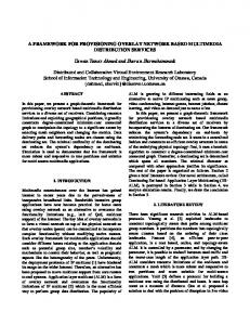
The flexible cell The manufacturing cell is composed by four working stations served by a conveyor system and its pallets with parts to be treated. Each working station has a robot and a vision system, two parts stocks and a working desk. This cell is represented in Figure 2. This working station can perform assembly, disassembly, control and calibration operations.
Brazilian Journal of Operations & Production Management 13 Volume 4, Number 1, 2007, pp. 5-21
The cell’s functional organization is hierarchic and modular, structured in 5 levels: i) Robots and local control, vision systems and conveyor system zones at the lowest level; ii) The coordination level is organized into a working stations local coordination (robot, vision system), a conveyor system coordination (organized and controlled by 5 modules) and a general coordination; iii) At the highest levels, the supervision, scheduling and planning (production management). Working station 2 transfer gates
Positioning Unit PU2
Positioning Unit PU2
Working station 5
Robot – Vision System Working desk Working station 3
S1 D7
Stock S1, S2
direction
V2 D5
D13
Transport system S5
V1 V2 D6
S4 D8 D2
D3 D4 S2
D9
S3 D10
A1 Working station 1
Proximity sensor Di Position sensor Di Working station 4
Stop/start Si Indexing jack
deviation jack
Figure 2. Robot-driven flexible cell
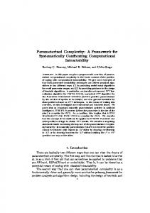
The CMM module The functional structure of a local coordination CMM node is shown in Figure 3. It proposes a more flexible structure to allow the choice and the configuration of a service issued from the upper level (taking a set of pre-defined services into account). Thus, the node’s functionality and flexibility increases by offering of this set of services in a layer and modular organization, leading to a local ‘virtual hierarchy’. This results in a better interface with the upper (general coordination) and lower levels (local control of robots and vision systems). All this functionality is extended to the maintenance module.
14
Brazilian Journal of Operations & Production Management Volume 4, Number 1, 2007, pp. 5-21
General Coord. GC
LIS (services)
(Service, operation)
LOCAL COORDINATION - LC
IP address Indexer (service, operation)
CM MODULE to transfer
MAINTENANCE MODULE
Parameters (e,pos,tp)
Assembly
Desassembl
Assembly
Transfer
Displace
Grab
to grade
to control
detach
control
part_ident
Place
to screw
Pattern_iden
grade
ass_ident
dess_ident
LIS (services)
Local Control of Robot Close pliers
CM
Open pliers
Displace, another services
Vision System go_to
M
Ident+loc
CM
To grade, to control, pattern_ident
M
Figure 3. The CMM module
Figure 3. The CMM module
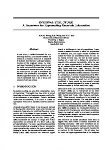
Let us start with the assembly of a spare part issued from the stock, on top of another part located above a working desk. The control, reference and maintenance models concerning this coordination level are described in Figure 4, and make up the CMM coordination module. The representation of these models is based on Petri Nets with Objects (PNO), where the tokens hold the information (token attributes). The interpretation associated to transitions based upon these attributes leads to the execution of tests and actions (Zamai et al., 1997). In the maintenance PN model, stochastic rates are associated to some transitions that model the random planning of a maintenance policies (preventive maintenance - βpm) as well as failure and repair/maintenance intervention rates (failure/corrective maintenance - λcm, duration and preparation rate - τc, τp, repair / maintenance intervention - µ) . A Markov graph (array) is considered in the statistic block for a numerical simulation and evaluation.
Brazilian Journal of Operations & Production Management 15 Volume 4, Number 1, 2007, pp. 5-21
Figure 4. CMM reference-control-maintenance models for coordination of working station
Let us consider the control model. The assembly service starts a sequence of low level services: ‘identify_ part’ service, which identifies the part’s location in order to recover it (offered by the vision system’s local control), ‘grabbing’ service which grabs and moves the part from and into a placing position, ‘placing’ service which corresponds to the assembly part and ‘grabbing’ service for the removal of the assembly part (offered by the robot local control (Figure 5)). The associated reference model represents the process restrictions (mutual exclusion of operations and estimated operational times). Communication between these models is implemented by means of a transition fusion method: as soon as the service control model ‘part_identification’ is requested, which corresponds to fi ring transition ‘tsd1’, the ‘tsd13’ transition, associated to
16
Brazilian Journal of Operations & Production Management Volume 4, Number 1, 2007, pp. 5-21
transition ‘tsd1’ at the reference model, is simultaneously fi red (under the condition that its input place ‘free_station’ is marked, meaning that the requested service is coherent with the process state). Therefore, the reference model evolves towards the ‘part_identification’ state. maintenance model
control models grabbing
placing
tsdm41
tsd41
tsdm21
tsd21
tsm21
tsm41
go_to
OP [acc_man] [n]
CM decision block
go_to tsf21
tsfm41
tsf41
tm2
tsdm42 tsm42
[stat_m,n] [n] ts
trop
tdeb
tsm22
open_pliers
IS
close_pliers
tsf42
MS
tsdm22
tsd22
tm3 MR
NC tsd42
CMM LL
NM
tm1
tsfm21
PM statistic block
tsfm42
[nd]
tsf22
r4
tsfm22
MST [n;stat_m]
trei
CMM HL [n;stat_m]
r2 reference models
pos
Legend:
tsdm21,41
Robot
tsd21,41
tsd22: start closing_pliers tsdm22: start closing_pliers (M state) tsf22: end closing_pliers tsfm22: end closing_pliers (M state) tsd42: start opening_pliers tsdm42: start opening_pliers (M state) tsf42: end opening_pliers tsfm42: end opening_pliers (M state)
go_to tsm21,41 tsf21,41
tsfm21,41
LIS statistic
[Do] transitions operation times tsfm42
tsdm42 tsd22
closing_pliers tsf22
tsf42
opening_pliers tsm42
tsm22 tsfm22 tsd42
tsdm42
Figure 5. Local command CMM models for robots
The request is transmitted to the lower level, in this case, the vision system’s local control. If the lower level execution report is not received within a temporal window defi ned by the reference model, the reference and control models can no longer evolve. A failure is detected and the monitoring process is triggered (detection, diagnosis, recovery).
Brazilian Journal of Operations & Production Management 17 Volume 4, Number 1, 2007, pp. 5-21
If the execution report is received within the temporal window, the control and reference models can evolve (simultaneous fi ring of ‘tsf1’ and ‘tsf13’). The reference model evolves towards the ‘free_station’ state and the control model can request the ‘grabbing’ service. Therefore, a simultaneous fi ring of ‘tsd2’ occurs in the control and reference models and the latter also changes to the ‘taken’ state. The service request is transmitted to the lower level, in this case, to the robot’s local control. At this level, the control model carries out a sequence of elementary controls over the process: ‘go_to’, then ‘close_pliers’ (Figure 5). Two reference models represent the process’ behaviour associated with the pliers and the arm movement. The evolution of the control and reference models is made as described previously. When this last sequence operation (‘close_pliers’) ends, an execution report of the ‘grabbing’ service (‘cr2’) is transmitted to the CMM module’s upper level. Then, the ‘place’ and ‘grab’ services are executed. Let us suppose that a failure is detected at the end of the fi nal assembly part operation: the ‘close_pliers’ end-of-execution report is not received within temporal window. Thus, the decision block requires a corrective maintenance action from the operator (CM-tm1-MR sequence at the maintenance model of the CMM module’s local control). The operator acknowledges the module in a maintenance state and the upper level is informed about it (OP-tdeb-MST/CMM NS sequence). At the upper level, this information will be taken into account by the decision block and by the operator, who will decide, or not, about also placing the module in the maintenance state (CMM LL-tm3-MR-tdeb-MST). The module’s maintenance state means the suspension of the ongoing operation and its registering due to its recovery (MST-tsm22-NC/IS sequence). At this moment the operator is able to require services or operations available in the control model, or trigger operation sequences that are different from the regular control (OP/NC-ts-MS-tsdmn). The detection mechanism still considers the process’ restrictions through the reference model (transitions ‘tsdmn’ and ‘tsfmn’). Sequences, tests or maintenance operations depend on the operator’s experience and can be formulated by means of a rule-based system (expert system). It is possible to use the local information system’s (LIS) data as a reference: failures historic data, interventions maintenance policies adopted, MTBF, MTT indexes, etc. Considering our case, when failure at the ‘close_pliers’ service is detected, the operator is able to request: • pliers opening (OP/HS-ts-MS-tsdm42-open_pliers sequence), and if the endof-execution report (opening/closure signal value is acknowledged and the strength sensor is in state 0) is received within the temporal window (leading to fi ring tsfm42 and marking NC), it is possible to conclude that the opening/ closing pliers device is working.
18
Brazilian Journal of Operations & Production Management Volume 4, Number 1, 2007, pp. 5-21
• pliers repositioning (OP/NC-ts-MS-tsdm21-go_to-tsfm21-NC sequence) to make a pliers closing test with maximum safety; • closing the empty pliers (MS-tsdm22-close_pliers sequence). If the end-ofexecution report (value of the closing/opening signal is acknowledged and the strength sensor has an empty closing value) is not received within the time window, it is possible to conclude that the closing device is not working (interruption of the air supply, for example). Once the failure is repaired, the operator is able to perform new tests, requesting a specific part in the stock (‘identify_part’ service of the CMM coordination module, after ‘taking’ and fi nally ‘placing’ it in the stock, for example). And fi nally, the operator must replace the control into a coherent state – to the breakdown initial state (registered by the IS location’s stick), i.e., at the beginning of the ‘taking’ service (OP/NC/IS-trei-MS-tsdm2 sequence) or proceed to the fi nalization of the suspended operation, before leaving it to the general control (OP/NC/IS-trop-MS-tsdm2 sequence). In both cases the reference models are equally replaced into coherent states. All interventions are registered in the Local Information Systems (LIS policy) to make future interventions easier. CONCLUSION This study presented a hierarchic and modular control-monitoring-maintenance architecture, organized in CMM modules. In each module the interaction of a control module, process’s reference models (allowing the detection of failures) and a maintenance module (consisting of a maintenance model and a statistics module) can be observed. This module allows different maintenance policies to be carried out - corrective and preventive/predictive ones. The statistics block, coupled to a local information system, enables the registration of all the information issued by the process and control, it estimates and establishes a preventive/predictive maintenance plan and helps the operator during a maintenance intervention. The maintenance model PN may simulate the system’s stochastic behaviour when subject to failures and maintenance procedures and repairs. The operator can access, via maintenance model, the services and operations offered by the control and can sequence them differently from the expected process. In addition, it is possible to, eventually, access services that are available, but are not being used in the current process. The evolution of reference models during the control stages and during the maintenance stage results in an assurance of a coherent use of the process. This integration process, the maintenance tasks integrated into the control and monitoring structure, are the main advantages of our approach. The proposed architecture is actually being implemented in a robot-driven flexible cell, connected to the Ethernet TCP/IP. Therefore, it is necessary to study the problems
Brazilian Journal of Operations & Production Management 19 Volume 4, Number 1, 2007, pp. 5-21
presented in a remote maintenance context, e.g.: the remote configuration of the CMM modules, network and devices, as well as the reliability, safety and real time conditions. Moreover, the planning and scheduling levels will be considered in detail leading to the defi nition of interfaces with the CMM nodes. The CMM architecture (its models) is based on a development cycle methodology that characterizes the following steps: modelling, analysis/simulation and implementation of the CMM modules. Then, the maintenance aspects may be taken into account from the concept stage to the operation stage of a flexible manufacturing system. The proposed modelling approach based on Petri nets allows a modular optimisation of the maintenance procedure. REFERENCES Bérenguer C.; Châtelet E.; Langeron, Y. (2004) “Modelling and simulation of maintenance strategies using stochastic Petri nets”, Proceedings of 4th International Conference on Mathematical Methods in Reliability Methodology and Practice, Santa Fe, New Mexico. Berruet P. (1998) “Toward an Implementation of Recovery Procedures for FMS Supervision”, Proceedings of Information Control Problems in Manufacturing, France, pp. 371-376. Bondavalli, A.; Filippini, R. (2004) “Modelling and Analysis of a Scheduled Maintenance System: a DSPN Approache”, The Computer Journal, BCS, Vol 47, No 6, pp. 634-650. Chaillet-Subias A.; Zamai, E.; Combacau, M. (1997) “Information flow in a control and monitoring architecture”, Proceedings of the IEEE Int. Symposium on Industrial Electronics, pp.53-58, Guimaraes, Portugal. Gershwin, S.B.; Caramanis, M.; Murray, P. (1998) “Simulation experience with a hierarchical scheduling policy for a simple manufacturing system”, Proceedings of the 27th IEEE Conf. on Dec. and Control, Vol 3, pp. 1841 – 1849. Ghoshal S. et al. (1999) “An Integrated Process for System Maintenance, Fault Diagnosis and Support”, Invited paper in Proc. IEEE Aerospace Conf., Colorado, USA. Giua, A.; DiCesare, F. (1994) “Petri net structural analysis for supervisory control”, IEEE Transactions on Robotics and Automation, Vol 10, Issue: 2, pp. 185-195. Gouvea da Costa, S. E.; Platts, K.; Fleury, A. (2000) “Advanced Manufacturing Technology: defining the object and positioning it as an element of manufacturing strategy”, Proceedings of the VI International Conference on Industrial Engineering and Operations Management, São Paulo. Jeng, W.-H; Liang, G. R. (1998) “Reliable automated manufacturing system design based on SMT framework”, Computers in Industry 35, pp.121-147. Künzle, L.; Valette, R.; Pradin-Chézalviel, B. (1999) “Temporal reasoning in fuzzy time
20
Brazilian Journal of Operations & Production Management Volume 4, Number 1, 2007, pp. 5-21
Petri nets”, Fuzziness in Petri Nets – Studies in Fuzziness and Soft Computing, Physica-Verlag, Vol. 22, pp. 146-173. Loures, E. R.; Paula, Busetti, M. A. (1999) “VIEnCoD - Proposal of an Environment CACSD integrated to an ERP system as a tool in the Support to the Control System Development Cycle Based on VXIbus / LabWindows and MATLAB Platform”, Proceedings of the 7th IEEE Int. Conf. on Emerging Techn. and Factory Automation, Spain, pp. 761-766. Ly F.; Toguyeni, A. K.; Craye, E. (2000) “Indirect predictive monitoring in flexible manufacturing systems”, Robotics and Computer Integrated Manufacturing, Elsevier Science Ltd., No 16, pp. 321-338. Ly, F.; Simeu-Abazi, Z.; Leger, J-B. (1999) “Maintenance terminology review”, Report of the Research Group of Safety Functioning Production, France. Mouss, H.; Mouss, N.; Smadi, H. (2004) “The Maintenance and Production: Integration Approach”. Proceedings of the 4th Internacional Conference on Mathematical Methods in Reliability Methodology and Practive, Santa Fe, New Mexico. Pascal, J-C. (2000) “A modular and hierarchical approach for supervisory control of batch processes”, 4th International Conference on Automation of Mixed Processes: Hybrid Dynamic Systems, German, pp.369-374. Santos, E. A. P.; Paula, M. A. B. de; da Silveira, M. R. (2004) “A methodology for modeling the control of a mechatronic manufacturing cell”, 9th Mechatronics Forum International Conference, Vol 1, pp. 1-6. Silveira, M. da; Combacau, M.; Boufaied, A. (2000) “Prognosis and recovery evaluation on flexible manufacturing supervision”, IEPM’01 International Conference on Industrial Engineering and Production Management, Quebec, Canada. Simeu-Abazi, Z. ; Sassine, C. (2001) “Maitenance Integration in Manufacturing System Evaluation and Decision”, International Journal of Manufacturing Systems, Vol 13, No 3. Srinivasan, V.S.; Jafari, M.A. (1993) “Fault detection/monitoring using time Petri nets”, IEEE Transactions on Systems, Man and Cybernetics, Vol 23, pp. 1155-1162. Tang, Y.; Zhou, M.C. (2001) “Design of reconfigurable semiconductor manufacturing systems with maintenance and failure”. Proc. of the IEEE International Conference on Robotics and Automation, Vol 1, pp. 559 – 564. Varvatsoulakis, M.N.; Saridis, G.N.; Paraskevopulos, P.N. (2000) “Intelligent organization for flexible manufacturing” IEEE Trans. on Robotics and Automation, Vol 16, Issue 2, pp. 180 – 189. Zamai, E.; Chaillet-Subias, A.; Combacau, M.; Bonneval, A. (1997) “A hierarchical structure for control of discrete events systems and monitoring of process failures”, Studies in Informatics and Control, Vol 6, No 1, pp. 7-15.
Brazilian Journal of Operations & Production Management 21 Volume 4, Number 1, 2007, pp. 5-21
Biography Eduardo de F. R. Loures received his B.Sc. degree in Electrical Engineering from the Universidade Tecnológica Federal do Paraná (UTFPR), Curitiba, Brazil, a MSc degree in Informatics from the Pontificia Universidade Católica do Paraná (PUCPR), Curitiba, Brazil, and a PhD in Systèmes Industriels, LAAS, France. He heads the Mechatronics Engineering Department at PUCPR. His research interests include Automated Manufacturing Systems, Failure Identification and Diagnoses, Business Process Management. Eduardo Alves Portela Santos received his B.Sc. degree in Mechanical Engineering from the Universidade Federal da Bahia (UFBA), Salvador, Brazil, a MSc degree in Mechanical Systems from the Universidade Federal de Santa Catarina (UFSC), Florianópolis, Brazil, and a PhD in Information Systems from the same university(UFSC). His research interests include Automated Manufacturing Systems, Business Process Management, and Conformance checking in business process. Marco A Busetti de Paula received his B.Sc. degree in Electrical Engineering from the Universidade Federal do Paraná (UFPR), Curitiba, Brazil, a MSc degree in Electrical Engineering from the Universidade Federal do Rio de Janeiro (UFRJ), Rio de Janeiro, Brazil, and a PhD in Electrical Engineering from the Universität Gesamthochschule Paderborn, UGP, Germany. His research interests include Integrated Systems, Automated Manufacturing Systems, and Business Process Management.