2013 IEEE International Conference on High Performance Computing and Communications & 2013 IEEE International Conference on Embedded and Ubiquitous Computing
A Convex Hull Based Optimization to Reduce the Data Delivery Latency of the Mobile Elements in Wireless Sensor Networks Ronghua Xu, Hongjun Dai* , Fengyu Wang and Zhiping Jia Dept. of Computer Science and Technology, Shandong University, Jinan, P.R.China Email:
[email protected],
[email protected],
[email protected],
[email protected] Abstract—Recent research shows that significant energy of sensor nodes can be saved in wireless sensor networks with a mobile element called Data Mule (DM) for data collection via short-range communications. However, a major performance bottleneck is the increased data delivery latency, so it is critical to optimize the DM motion, including the path and the speed. In this paper, path selection is formulated as a combined optimization problem where speed control is associated within the problem as constraints. A three-step geometric method is proposed to solve the problem: firstly the convex hull structure is used to define a visiting order of nodes, then the detailed path intervals are adjusted to accord with the optimal speed control plans and finally, the number of turns in the path is reduced through global optimization. The experiments show that the latency is decreased to 80-85% compared with the previous methods, and about 1.3 times of the lower bound minimal value. Besides, the proposed method outperforms the previous methods by an average 10% decrease of the data delivery latency in the overall cases of communication ranges.
I.
C1
c2
c1
c3
c4
Fig. 1.
I NTRODUCTION
In Wireless Sensor Networks (WSNs), the traditional multihop data forwarding faces many challenges such as excessive energy consumption and imbalanced data load [1], [2]. In recent studies, a mobile element called Data Mule (DM) is employed for data collection [3] in many sensor network applications [4], [5]. The DM sets out from a base station, visits each node to collect data within one hop, and brings all data back to the station. However, it is very important to reduce the DM travel time and to minimize the Data Delivery Latency (DDL). This is generally studied from the aspects of path selection, speed control and job scheduling [6]. In this paper, a geometric method of path selection is presented to minimize the DDL by achieving both the optimal path and the optimal speed control plans.
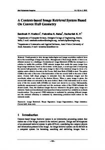
The basic network scenario with one DM and two sample paths
so that the job schedule can be fulfilled in the minimal time. In [7], job scheduling and speed control are considered together as one-dimensional Data Mule Scheduling (1-D DMS) problem, which simultaneously determines both a speed-time profile and a feasible job schedule. 1-D DMS also decides the travel time of the DM along the selected path. In [8], the Message Ferrying (MF) scheme relates path selection to the well-studied Traveling Salesman Problem (TSP). Following the TSP tour, the DM visits each node, stops at its location to execute the data collection job, and then moves on to the next. In [9], [10], they point out that the effective communication areas of nodes can be simplified as disks on the plane, and the DM only needs to pass through these disks. Hence, path selection can be transformed into the Traveling Salesman Problem with Neighborhoods (TSPN) and the key is to find the intersected points (also called hitting points) within each disk. To simplify the search for hitting points, the Label Covering Tour (LCT) [11] constructs an undirected complete graph having vertices at nodes’ locations and conducts search on the edges. Each edge is attached with a set of labels if the communication areas of the labeled nodes intersect with this edge. Path selection is re-defined by a tour, the edges of which cover all the labels (nodes). The principle of the above path selection formulations is to find a TSP tour of the minimal length. Nonetheless, the shortest tour does not result in the minimal DDL. For example, though P2 is shorter
Among these aspects, path selection determines the trajectory of the DM and ensures that it traverses the nodes’ communication areas. For example, in Figure 1, P1 and P2 are two sample paths selected by different methods. P1 intersects each node at the center of the communication area while P2 intersects at the edge, sometimes at only a single point. The process of data collection from a unique node is treated as a separate job and the execution time of the job is specified by the data collection time. Job scheduling determines a feasible schedule of the data collection jobs. Speed control is conducted on the selected path and determines the DM speed changes * Hongjun Dai is the corresponding author
978-0-7695-5088-6/13 $31.00 $26.00 © 2013 IEEE DOI 10.1109/HPCC.and.EUC.2013.322
C2
2245
II.
than P1 in Figure 1, its travel time may be longer because P2 mostly intersects around the border of the communication areas where signal quality is poor and data transfer rate is low. The DM needs to decelerate or even stop more often to coordinate with the longer data transfer time. However, little work is attempted to combine 1-D DMS within path selection for the optimal speed control plans.
R ELATED W ORK
A. Schemes to Reduce Data Delivery Latency Many schemes are proposed to reduce the data delivery latency with controlled mobility [17] through solving three subproblems: path selection, speed control and job scheduling [11]. Path selection can be described as a special case of TSP, TSPN, LCT, etc. With the TSP formulation [8], [18], it can be solved by exact or approximate algorithms, such as the Concorde TSP solver. To solve TSPN [9], [10], the basic idea is firstly to construct a TSP tour at sensor locations and secondly to search within each communication area for the intersected points in the order of the TSP visit. Due to the NP-hardness of TSPN, only theoretical values are obtained by approximation or heuristic algorithms. To simplify the search of the intersections, the LCT formulation [2], [11] constructs an undirected complete graph, on which a TSP tour is found. The shortest label-covering tour is optimized by shortening the TSP tour using dynamic programming. The main principle of the above formulations is to search for the optimal TSP tour.
Besides, path selection can be treated as a geometric problem to find a closed continuous moving trajectory of a point in the plane on request that the trajectory intersects with all the disks. In [2], [12], the LCT tour is improved by a series of geometric designs of Combining, Skipping and Substituting the selected certain nodes (named as CSS methods). Some geometrical strategies are also adopted, such as the Welzl’s algorithm [13] to compute the smallest enclosing circle of a finite set of points. While, in computational geometry, the convex hull is a basic structure expressing many fundamental geometrical properties. The convex hull of a given set X of points in the Euclidean space is the minimal convex set containing X. It is useful to explain problems as half-space intersections, and the farthest-point voronoi diagram [14]. In addition, the convex hull structure can also help to search for the optimal TSP tour [15] [16]. As path selection is essentially to find an optimal TSP tour, the convex hull may also be used to help plan the path of the DM.
Speed control is often conducted under the predefined tour obtained by the path selection algorithms. The control strategies include constant speed, variable speed and generalized variable speed. In terms of data delivery latency, the variable speed control [19], which means the speed can be changed with the amount of the collected data, performs better than the constant speed control [20], [21]. The generalized variable speed control [7] is more practical to accommodate the jobs with different execution time. Job scheduling could be combined into path selection, that is, the order of the TSP visit serves as the schedule of the collection jobs. Job scheduling could also be combined into speed control as the 1-D DMS problem, which determines the speed control plan and the job schedule simultaneously. The schedule strategies can be Earliest Due Date (EDD), Latest Release Time (LRT) etc. However, these problems can be further combined together to reduce the travel time of the path. Especially, the speed control plans can be considered into path selection to acquire both the optimal path and speed.
In this paper, we propose a novel method of path selection in a geometric way with the help of the convex hull structure. Besides, to coordinate with the optimal speed control and reduce the travel time, the path is optimized progressively. The general idea is that an optimal visiting order of nodes is firstly computed following which a set of paths may be obtained. Among these paths, an initial path is chosen by connecting the points at nodes’ locations in order. The 1-D DMS on the initial path is realized to compute the initial travel time. As the detailed intervals of the path have not been operated yet, the travel time is not optimal and the resulted speed control plan is used for further optimization of the intervals. Based on the above idea, we formulate the path selection problem as an optimization problem aiming at the minimal travel time. Speed control and job schedule are associated with the problem as constraints. Under the formulation, a 3-step geometric method is proposed to solve the problem. In the first step, with the convex hull structure, a visiting order of nodes and an initial path are obtained. In the second step, the 1-D DMS on the initial path conversely affects the adjustment of the intersected intervals in the path. Finally, the global optimization strategy manipulates each interval with the objective of the minimal number of turns. After that, we demonstrate the performance of the proposed method through various simulation experiments. Compared with TSP, LCT and CSS, the travel time achieved by our method is only 8085% of the best ones achieved by the previous methods. The proposed method outperforms other methods by more than 10% decrease in the total travel time. Besides, to investigate the near optimality, the proposed method is also compared with the Lower Bound minimal (LB-mini) value and it is about 1.3 times of the latter. Due to the global optimization strategy, the finally obtained tour is smoother and contains the smaller number of turns than the previous methods, suggesting the effectiveness of the proposed method.
B. Geometric Path and Convex Hull In [22], [23], path selection has been treated as a basic geometric problem. When the DM is simplified as a point in the plane and the communication area of a sensor node is abstracted as a circular area, to select a DM path is to constitute a continuous curve of the moving point on condition that this curve intersects with all the circular areas. The transformed problem can be divided into a serious of fundamental problems, such as the line segment intersection problem, motion planning problem [14]. In [22], path selection is interpreted as position change of the DM from one point to another point. It also gives the interpretation of constructing paths of the multiple DMs at the same time. The whole communication areas are segmented into a structure called the polar grid. The optimal positions of DMs at one epoch are decided by choosing the minimum enclosing circles and the positions over several epoches are changed by rotating the polar grid continuously. In [2], [12], they deal with path selection differently. They assume the data collection time is negligible and geometry optimization strategies are adopted to progressively reduce the tour length. 2246
In computational geometry, convex hull is a basic structure expressing many potential properties. It serves as a tool to solve problems such as the shortest transversal, half-space intersections, the farthest-point voronoi diagram [14]. In recent study, convex hull can also be used to search for the optimal TSP tour [15] [16]. A convex hull TSP property shows that every Euclidean TSP has an optimal solution if every point lies on the boundary of the convex hull [24]. For the TSP points inside the convex hull, an insertion criterion is needed to connect these points into the outer convex hull boundary. The final TSP tour lengths deviate on average within 0.75% of the optimal solutions. Besides, the insertion criterion produces a range of solutions rather than a single solution, and better solutions may be found by the insertion than by some conventional TSP algorithms.
C1
C2
F
0
F
F
2
2
p2
q1
F
q2
1
3 0
p3
p1
F
F
1
q3
0
q4
F
According to the convex hull property of TSP, a series of convex hull based heuristic algorithms to find a TSP tour are proposed [15], [16]. The general procedure of these heuristics is similar, where the convex hull is treated as an initial subtour and a starting point in the sub-tour and a direction are first chosen. The current edge is therefore from the selected point to its adjacent point in the direction. Then, a test would check each interior point and decide whether it is closest to the current edge. If yes, the interior point would be inserted into the current edge, otherwise the point would be passed and other interior points would be checked. After the test, the procedure would move on to the next point of the subtour in the selected direction. The procedure repeats until all interior points are inserted and the tour is complete. Since path selection is essentially to find an optimal TSP tour, the convex hull may also be used to help plan the path of the DM.
3
p4
F
4
0 0
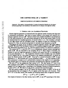
Fig. 2. The selected path in the network is modeled with illustrated symbols.
Ci centered at ci with the radius of ri , i = 1, 2, 3, ...N . The position where the base station locates is the point B. Let P denotes the path of the DM, and P is composed of a series of points, in which the first and the last point is B. As is shown in Figure 2, χi stands for the set of points where P intersects with Ci , χi0 denotes the set of points where the DM comes out of the former node and orientates to node i. Therefore, the problem of path selection is transformed into a geometric problem, that is to find a closed curve from B to B intersecting with all these circle areas, constrained by χi ̸= ∅
C. Motivation
(1)
When the DM moves in space along the selected path, the dimension of time is imported into the problem. The position change of M along the time dimension can be denoted by the variation of velocity v. Constrained by the kinematics factors of the DM, v ranges from 0 to the maximum value vmax . The derivative of the velocity is denoted by the acceleration a ranging from 0 to amax . Suppose the total time spent on the whole path is T . Hence, the speed control problem is to find the time-velocity profile from 0 to T , constrained by
The convex hull TSP holds the advantages of capitalizing on one of the well-known characteristics of an optimal tour and being flexible to obtain different tours by simply changing the insertion criterion. In addition, the existing path selection schemes are so separated from 1-D DMS that the travel time can be further reduced when path selection can be accommodated to it. As a geometric method owning the information of the whole network, the convex hull method can easily adjust the location intervals of the path according to the time-speed profile of 1-D DMS. In this paper, we adopt a 3-step heuristic algorithm to compute the travel time along the path selected by the convex hull approach. In the other way, the path can be further optimized according to the resulted speed control plan.
0 ≤ v(t) ≤ vmax
0 ≤ a(t) ≤ amax
(2) (3)
In this work, the WSN consists of a fixed number of static sensor nodes which are sparsely deployed around the sensing environment. Suppose the locations of these nodes are known in advance through the technology of the Global Positioning System (GPS) or the distributed localization algorithms [25] in WSN. The DM is relatively expensive and can be periodically recharged and we assume that there is only one DM and no multi-hop data forwarding between any sensor nodes. Besides, during each round of DM travel, the data to be collected in each node is fixed.
Once the DM enters the circular communication area, data collection begins. Data can be communicated while the DM is moving. The amount of data collected from Ci is denoted by Di . Suppose the data transfer rate is constant f , and the collecting time is ei = Di /f . The job scheduling problem is to allocate each location job enough time to collect all the data. Suppose |χi | is the time allocated to the location job Ji within the point set of χi . There may be many location intervals within χ as the DM may pass through Ci more than once. |χi | is the total time spent in all the intervals, constrained by |χi | ≥ ei (4)
The DM can be simplified as one point on the plane, say M . The communication area is abstracted as a circular area
Taking all the three problems together, the associated problem is defined with the objective of the minimal T , through
III.
P ROBLEM D EFINITION
2247
finding an optimal path and optimal speed control plan under the above four constraints. IV.
a greedy one and the main process includes two procedures. In the first procedure, the convex layers of all center points are constructed by obtaining the convex hull progressively, as shown in Algorithm 1. In the second procedure, points from the inner layers are merged into the outer layers on the principle that the added free position is minimal. By merging each point into the outmost layer, the permutations of the inner convex hulls layers may be destroyed. Therefore, to guarantee global optimization, the permutation of the inner layers is also maintained in the combination any two consecutive layers, as shown in Algorithm 2. When all the points of ci are added, a complete order is acquired which acts as the final permutation.
T HE C ONVEX HULL BASED M ETHOD
When the DM is moving along the path, there are only two states of it: the unfree state in which it is busy with data collecting and the free state when no data is collected. The time spent in the unfree state is fixed with the data collection time of ei while the time in the free state is uncertain as the length and velocity may be various. Hence, the total travel time mainly depends on the time when the DM is in the free state. Furthermore, the free state can occur under two circumstances: when the DM is inside the communication areas, this kind of free state time is called the InFreeTime (IFT); when the DM is outside of any communication areas, the free state time is called the OutFreeTime (OFT).
Algorithm 1 Construct the convex layers Require: set S = {B, c1 , c2 , c3 , ...cn }, the number of convex layers N is 0 1: while S is not null do 2: construct the convex hull of S; 3: N ← N + 1, LN ← the points in this convex hull 4: S ← S − LN 5: end while 6: return N , L1 , L2 , ...LN
In this paper, both IFT and OFT are minimized through selecting an optimal path. In the method, three steps are employed: it first minimizes OFT by deciding the visiting order of sensor nodes with the help of convex hull, and acquires an initial path P0 ; then it minimizes IFT by considering speed control and relaxing the tight interval of P0 , and finally it tries to reduce the number of turns in the path by global optimization to decide the proper positions of each interval.
Algorithm 2 Merge convex layers to form the permutation of nodes Require: the permutation P er is initialized as L1 , and is updated progressively 1: for each point c in L2 , from the one which is closest to B and in the clockwise direction do 2: scan P er from # B in $the same direction, and find the convex edge P i , P i+1 from c to which the free position is shortest 3: find the minimal sum of free to decide the !−−−position −− −−&−−−→" %−−i−−−−− i i+1 i−1 order of c, P , P min P P , c, P i+1 P i+2 , & % where P i , c, P i+1 is all the possible permutations of P i , c, P i+1 4: choose the order with the minimal sum and add c to P er, 5: end for 6: for currLayer ← L3 to Lk do 7: for each point c in currLayer, from the one which is closest to B and in the clockwise direction do 8: scan P er in the same direction, and find the point P j from c to which the free position is shortest 9: compute the sum of free position, and find the minimal to decide the order of" c, P j such that !−−−− −−−−−−→ −−−−−−−−−−→ min P j−1 P j cP j+1 , P j−1 cP j P j+1 10: choose the the order with minimal sum and add c to P er 11: end for 12: update currLayer to the next layer 13: end for 14: return P er
A. minimize OFT The free position indicates the location where the DM is in the free state and is outside of any circular communication areas. The sum of the free positions adds up all the free locations of the whole path. OFT is the travel time spent on the sum of all the free positions. Assume that the speed is the maximal during the sum of the free positions. Hence, OFT is mainly decided by the total length of the free positions. The definitions and calculations are shown as follows: The free position between two isolated consecutive nodes ci and cj which are not intersected, is expressed as: − → (5) c− i cj = distance (ci , cj ) − ri − rj If ci and cj are intersected with each other, then − c =0 c−→ i j
(6)
The free positions among a series of k isolated continuous nodes ci ci+1 ci+2 ...ci+k , is calculated as: − −−−→ = − c− c−→ + − c−−− c−→ + ... + − c−−−−− c−→ (7) c−...c i
i+k
i i+1
i+1 i+2
i+k−1 i+k
The minimal free positions among the k series of con−−−−−−−−−−−−−→ tiguous nodes is indicated by min⟨ci ci+1 ci+2 ...ci+k ⟩, where ⟨ci ci+1 ci+2 ...ci+k ⟩ denotes all the possible permutations of the k nodes. Suppose the visiting order of nodes is represented by the visiting order of the locations of ci . A possible permutation is ⟨c1 , c2 , ..., cn ⟩, which means that the DM starts from point B, visits c1 , c2 , ..., and after visiting cn , goes back to B. The radius of B is zero. Hence, the free position of the !−total −→ −→" −→ + − whole travel is calculated as min Bc1 + − c1−c−2− ...c cn B . n The visiting order or permutation of ci is crucial to the total free position. To decide the permutation, our method is quite
In Algorithm 1, it takes the locations of all points as inputs and provides the convex layers as outputs. The outmost convex hull is called the first convex layer L1 and all layers from the outer to the inner are numbered as L1 , L2 , ...LN . 2248
The procedure of merging the convex layers is explained in Algorithm 2. A global permutation P er records the current order of the points merged. P er is initialized by L1 and is gradually updated by the inserted points in the inner layers. The insertion criterion ensures that the added free position due to points insertion is minimal.
Algorithm 3 The length adjustment of intervals to optimize IFT Require: P0 , χi , ei , T0 , η the positive parameter from 0 to 1 1: ∆l = 0, ∆l records the length change of P0 2: v ¯ = PT00 3: sort the intervals χi by the their average velocities with the smallest one at first 4: for each χi in P0 do 5: ε = v ¯ei − χi 6: if ε is negative then 7: choose a (negative value ∆li =)η ·ε such that li = χi +∆li ' and li ∈ ri , 2ri 1 + cos (α) 8: ∆l = ∆l + ∆li 9: else if ε is positive then 10: choose a positive value ∆l ·ε such that ∆l+∆l i ≤ 0, ( i = η' ) li = χi + ∆li and li ∈ ri , 2ri 1 + cos (α) 11: ∆l = ∆l + ∆li 12: else 13: ∆li = 0 14: li = χi 15: end if 16: end for 17: return li , the optimal length of interval χi ;
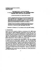
This process is further illustrated by an example in Figure 3. The sampled points are classified as L1 , L2 , L3 from the outer to the inner. In Figure 3(a), the three layers are clearly marked and the ordered L1 is initialized as the permutation. In Figure 3(b), the free position from the points in L2 to points in L1 are calculated and the orders with minimal free position are selected. c2 is inserted between c1 and c4 and c6 is between c5 and c7 , so as c9 and c13 . After these points insertion, the permutation is updated by L1+2 with the order of L1 and L2 maintained. There are only two points of L3 left in the network. The merge process of c3 and c12 is clarified in Figure 3(c) after which the permutation is completed by L1+2+3 . Figure 3(d) shows the final permutation of all points and the initial path is constructed by connecting all these points sequentially. B. Minimize IFT Following the visiting order of nodes in the first step, we can get an initial path P0 which starts at point B, passes through ci according to the order in P er and goes back to B. The Heuristic Algorithm (HA) of the 1-D DMS realization in [7] is executed to obtain the speed control plans of the path P0 , including the speed-time profile and the total travel time. Although the OFT is minimal, the travel time may not. This is because P0 is longer as to cover every center point of the circle and the feasible location intervals of each job are as long as the diameter of the circle. The speed-time profile is not optimal. IFT results from the diverse speed control plans.
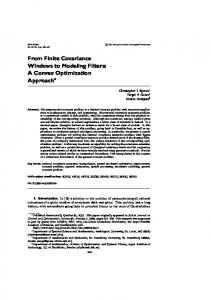
considered to decide the exact locations of each interval. The question can be described as, given the order of circles and the intersected interval length within each circle, to search for a serious of end points (pi , qi ) of the intervals such that all these end points can be connected into a unique path. The solution is the set of end points while the objective is simultaneously both the minimal path length and the minimal number of turns held by the path. Figure 4 illustrates the problem where seven intervals are presented and the number of the circle indicates its order. Since circles may intersect, the intervals within the intersected circles can be treated as one entity interval of blocks denoted by the solid lines. The lengths of these solid lines are calculated by Algorithm 3 and the speed of the DM along these lines is variable so that the data collection jobs can be completed. Thus, the problem hereby is to decide a complete tour connecting all these circles on condition that all intervals are delineated with the optimal lengths.
The length of the feasible location interval of Ji is |Ji | = 2ri and the average velocity along the interval is v¯i . If 2ri /v¯i > ei in the plan, IFT exists. Conversely, the length of the interval can be adjusted to change the speed control plan. However, the interval is not tolerable to be lengthen or shorten without any limits. The maximum value is determined by the radius ri and the minimum steering angel α of the DM and the minimum value is ri to guarantee the communication quality. Thus, the ' length of χi ranges from ri to 2ri 1 + cos (α).
With the elongation of the interval χ, the whole path becomes longer and the travel time may not be reduced. Hence, it is efficacious for the adjustment to increase the whole average velocity of the path. The average velocity is always confined by the tight intervals. In HA, the plateau speed is fulfilled within the tight intervals and it constitutes to the short-board of the entire speed profile. To conclude the above analysis, both the length of the whole path and the tight intervals are considered in the optimization of the IFT intervals. The principle is set to increase the average velocity while not to lengthen the whole path. The adjustment procedure is explained in Algorithm 3.
The problem is similar to the global optimization problem which is very hard. The the global trend of objective function is constructed through an extended discrete fourier transformation and an inverse discrete fourier transformation. The problem is constrained by the predefined visiting order and lengths. Thus it can be solved through the optimal searching route strategies. We present a simple scheme of the global optimization search. It works as the follows, from point B of the initial path P0 , the minimal OFT interval from B the block B1 is first searched, and then within B1 , the optimal lengths p1¯q1 to which the angle from B is minimal is scanned out. After that, it iterates in the visiting order until all blocks are connected and returns B. The process is also illustrated in Figure 4. Within the intersected areas, such as C5 , C6 , C7 , points from each intersection are connected to form the data collection intervals. The IFT intervals may be curves or straight lines, as the velocity of the DM can be various accordingly.
C. Global Optimization After the above two steps, a visiting order and a set of optimized interval of χ are gained. But the entire path is still uncertain. Hence, in this step, more practical factors are 2249
!%
!$
!%
!$ !'
!!
!'
!!
!#
"!
""
!!% !!$
Fig. 3.
!'
"#
!)
!!"
"#
!!"
"!!"
!!*
!!%
!!#
!)
!!*
!&
!#
!"
!(
!!"
!)
"!!"!# !!$
!!!
!#
!"
!( !!*
!!%
!!#
!!$
!!!
!'
!!
!&
!#
!"
!(
!%
!$
!!
!&
!& !"
!%
!$
!!"
!!!
!( !!*
#*
!!%
!!#
!)
!!$
!!# !!!
Demonstration of convex hull merge to minimize OFT and to find an initial path P0 .
c3 q2
c2
c4
p3
q4 p2
q1
p5
c1 c6
c5
p1 q7
Fig. 4. order.
c7
The global optimization problem is to search for the end points in
V.
P ERFORMANCE A NALYSIS
We evaluate the performance of the convex hull based 3step method by numerical experiments and compare it with the TSP, the LCT and CSS algorithm in terms of the travel time, the tour length, and the number of turns. To see the near optimality of the proposed method, the LB-mini solution is also presented, the path of which is the lower bound of the TSPN tour and the velocity is constant with the maximum value. The effect of the control parameter η in the second step to adjust the interval length is also assessed. Based on the parameters from the real systems in [26], the nodes are uniformly deployed at random in a sparse circular sensing field with the radius of 500m. The Graham’s scan algorithm [27] is adopted to construct the convex hull of the points. For 1-D DMS, the communication time within each node is identical with 10s. To calculate the travel time, the maximum absolute acceleration is amax =1m/s2 , and the maximum speed vmax =10m/s to simulate the motion of a helicopter as in [28]. The minimum steering angle is 30◦ .
Fig. 5.
Travel time with different number of sensor nodes.
A. The travel time The proposed method outperforms both LCT and CSS in terms of the resultant travel time noticeably, as shown in Figure 5 (where the communication radius is 30m) and Figure 6 (where the number of sensor nodes is 20), where TSP represents the travel time of the optimal TSP tour, CSS is that of the CSS tour and LCT represents the time obtained after the label-covering algorithm. In Figure 6, as the number of nodes increases, the travel time achieved by our proposed method is 80-85% of that obtained by LCT, and is about 1.3 times of the LB-mini value, which cannot be achieved by any practical algorithms. In Figure 6, when the communication radius is lower, the difference between these methods is not obvious and they are all much larger than the LB-mini. This is because in this case, the communication radius effects little on the final tour compared to the wide-range monitoring field. As the communication radius increases, the advantage of our algorithm is more obvious, and it outperforms all other algorithms by an average 10% decrease in the travel time in the overall cases of communication radiuses.
2250
Fig. 6.
Fig. 8.
The travel time with different communication radius.
Effect of η on the travel time. 600
400
200
0
−200
−400
−600 −600
Fig. 7.
Tour length with different communication radius.
−400
−200
0
200
400
600
Fig. 9. The number of turns obtained by the proposed algorithm (30 nodes).
B. The tour length and the effect of η
frequent stops tend to make the travel time longer due to regular decelerations and accelerations. Besides, though the CSS tour is the shortest, it tends to intersect the communication area of each node only at a point, the DM needs to stop at the point to collect data. As a result, the travel time for a CSS tour is not as good as expected from its tour length.
The comparison of the tour length is shown in Figure 7. Though the CSS tour is the shortest, its travel time is not. And though the proposed path is not the shortest, the travel time is the smallest. The graph suggests that the minimal length of the tour does not mean the minimal travel time, which can only be acquired by the optimal speed control plan. The control parameter η in the step of the IFT optimization directly affects the resultant tour. To show its effect, the simulation is based on 20, 30, and 50 sensor nodes, respectively, with communication distance of 30m.
VI.
C ONCLUSION
In this paper, we study the path selection problem of a DM in WSNs. The aim of the problem is the minimal travel time to improve data collection efficiency. Firstly, we present an associative formulation of path selection where the speed control and job scheduling are considered as constraints. Then the 3-step method is proposed to find an optimal path. The convex hull structure is harnessed to obtain a visiting order of
From Figure 8, not surprisingly the tour length decreases as η increases. Furthermore, when η enlarges to some limited value, the tour length bounces back, because there is an optimal value for the best result which produces the optimal speed control plan. For different number of nodes, the limited values are different. For the case of 20 nodes, the trend is not obvious since the tour is already optimal and will not change with η. This also verifies the stability of the proposed method from another aspect.
600
400
200
C. The number of turns
0
The Figure 9 and 10 explain the reasons of the above results. In this example, though the proposed tour is longer than the LCT tour, it contains a much smaller number of turns. This is reasonable since, in the third step of the proposed method, the global optimization strategy is harnessed for the minimal number of turns possible. When there is an acceleration constraint, the DM needs to stop at each turn and thus more
−200
−400
−600 −600
Fig. 10.
2251
−400
−200
0
200
400
600
The number of turns obtained by the LCT algorithm.
nodes in which OFT is the minimal. Intervals are adjusted to further reduce the IFT and after that the global optimization strategy is employed to search for the locations of the adjusted intervals. Simulation results show that the proposed method achieves satisfactory performance under a range of settings and outperforms previous methods by more than 10% decrease in terms of the travel time. Besides, the number of turns in the final path is also smaller than that of previous tours. Therefore, the convex hull based method for path selection saves more time of the DM and improves the data collection efficiency greatly.
[9] [10] [11] [12]
Despite the fact that the proposed method performs well, there are some limitations. First, only the cases with a unique DM in the network are focused on in this paper although the idea is also applicable to the cases with multiple DMs as the path of each DM can be selected by the 3-step method. Second, the HA algorithm is called to associate 1-D DMS into path selection. A thorough analysis of the speed control and job schedule may further reduce the travel time. Notwithstanding the limitations, the experiment results do exhibit the more decreased travel time than previous methods, verifying the effectiveness of our associative formulation and the convex hull based method.
[13]
[14] [15] [16] [17]
ACKNOWLEDGMENT This work is supported by the National Science Foundation of China under Grant No. 61070022; the Shandong Province Young and Middle-Aged Scientists Research Foundation of China under Grant No. 11150004021003; and the Independent Innovation Foundation of Shandong University under Grant No. 2010TS008.
[18] [19]
R EFERENCES [1]
[2]
[3] [4]
[5]
[6] [7] [8]
[20]
X. Xu, J. Luo, and Q. Zhang, “Delay tolerant event collection in sensor networks with mobile sink,” in Proceedings of the 29th conference on Information communications, ser. INFOCOM’10. Piscataway, NJ, USA: IEEE Press, 2010, pp. 2471–2479. L. He, J. Pan, and J. Xu, “Reducing data collection latency in wireless sensor networks with mobile elements,” in Computer Communications Workshops (INFOCOM WKSHPS), 2011 IEEE Conference on, april 2011, pp. 572 –577. R. C. Shah, S. Roy, S. Jain, and W. Brunette, “Data mules: modeling and analysis of a three-tier architecture for sparse sensor networks,” Ad Hoc Networks, vol. 1, no. 2-3, pp. 215 – 233, 2003. M. Todd and etc, “A different approach to sensor networking for shm: Remote powering and interrogation with unmanned aerial vehicles,” in In Proceedings of the 6th International workshop on Structural Health Monitoring, 2007. A. Mainwaring, D. Culler, J. Polastre, R. Szewczyk, and J. Anderson, “Wireless sensor networks for habitat monitoring,” in Proceedings of the 1st ACM international workshop on Wireless sensor networks and applications, ser. WSNA ’02. New York, NY, USA: ACM, 2002, pp. 88–97. R. Sugihara, “Controlled mobility in sensor networks,” Ph.D. dissertation, University of California at San Diego, La Jolla, CA, USA, 2009, aAI3359040. R. Sugihara and R. K. Gupta, “Speed control and scheduling of data mules in sensor networks,” ACM Trans. Sen. Netw., vol. 7, no. 1, pp. 4:1–4:29, Aug. 2010. W. Zhao, M. Ammar, and E. Zegura, “Controlling the mobility of multiple data transport ferries in a delay-tolerant network,” in INFOCOM 2005. 24th Annual Joint Conference of the IEEE Computer and Communications Societies. Proceedings IEEE, vol. 2. IEEE, 2005, pp. 1407–1418.
[21] [22]
[23] [24] [25]
[26] [27] [28]
2252
B. Yuan, M. Orlowska, and S. Sadiq, “On the optimal robot routing problem in wireless sensor networks,” IEEE Trans. on Knowl. and Data Eng., vol. 19, no. 9, pp. 1252–1261, Sep. 2007. O. Tekdas, V. Isler, J. H. Lim, and A. Terzis, “Using mobile robots to harvest data from sensor fields,” Wireless Commun., vol. 16, no. 1, pp. 22–28, Feb. 2009. R. Sugihara and R. K. Gupta, “Path planning of data mules in sensor networks,” ACM Trans. Sen. Netw., vol. 8, no. 1, pp. 1:1–1:27, Aug. 2011. L. He, J. Pan, and J. Xu, “A progressive approach to reducing data collection latency in wireless sensor networks with mobile elements,” IEEE Transactions on Mobile Computing, vol. 12, no. 7, pp. 1308–1320, 2013. E. Welzl, “Smallest enclosing disks (balls and ellipsoids),” in New Results and New Trends in Computer Science, ser. Lecture Notes in Computer Science, H. Maurer, Ed. Springer Berlin Heidelberg, 1991, vol. 555, pp. 359–370. M. de Berg, M.and van Kreveld, M. Overmars, and O. Schwarzkopf, “Chapter11, convex hulls,” in Computational Geometry: Algorithms and Applications. Springer, april 2000, pp. 2 –8. J. N. MacGregor and C. Yun, “Human performance on the traveling salesman and related problems: A review.” Journal of Problem Solving, vol. 3, no. 2, pp. 1 – 29, 2011. M. S. and S. A., “Optimum path planning using convex hull and local search heuristic algorithms,” Mechatronics (Oxford), vol. 7, no. 8, pp. 737–756, 1997, eng. A. Kansal, A. A. Somasundara, D. D. Jea, M. B. Srivastava, and D. Estrin, “Intelligent fluid infrastructure for embedded networks,” in Proceedings of the 2nd international conference on Mobile systems, applications, and services, ser. MobiSys ’04. New York, NY, USA: ACM, 2004, pp. 111–124. R. Moazzez-Estanjini and I. Paschalidis, “On delay-minimized data harvesting with mobile elements in wireless sensor networks,” Ad Hoc Networks, vol. 10, no. 7, pp. 1191 – 1203, 2012. A. Somasundara, A. Kansal, D. Jea, D. Estrin, and M. Srivastava, “Controllably mobile infrastructure for low energy embedded networks,” Mobile Computing, IEEE Transactions on, vol. 5, no. 8, pp. 958 –973, aug. 2006. M. Ma and Y. Yang, “Sencar: An energy-efficient data gathering mechanism for large-scale multihop sensor networks,” Parallel and Distributed Systems, IEEE Transactions on, vol. 18, no. 10, pp. 1476 –1488, oct. 2007. G. Xing, M. Li, T. Wang, W. Jia, and J. Huang, “Efficient rendezvous algorithms for mobility-enabled wireless sensor networks,” vol. 11, no. 1. IEEE, 2012, pp. 47–60. W. Poe, M. Beck, and J. Schmitt, “Achieving high lifetime and low delay in very large sensors networks using mobile sinks,” in Distributed Computing in Sensor Systems (DCOSS), 2012 IEEE 8th International Conference on, May 2012, pp. 17 –24. Y. Zhao, Z. Yang, and H. Wu, “Local information guided autonomous exploration in sensor networks: Algorithms and experiments,” Computation Communacation, vol. 35, no. 9, pp. 1115–1124, May 2012. D. L. Applegate, R. E. Bixby, V. Chvatal, and W. J. Cook, “The traveling salesman problem: a computational study,” 2011. N. Patwari, J. N. Ash, S. Kyperountas, A. O. Hero III, R. L. Moses, and N. S. Correal, “Locating the nodes: cooperative localization in wireless sensor networks,” Signal Processing Magazine, IEEE, vol. 22, no. 4, pp. 54–69, 2005. “Powerbot,” [online], vol. Available: http://www.com/msg/10/31/4.php. F. P. Preparata and S. J. Hong, “Convex hulls of finite sets of points in two and three dimensions,” Communications of the ACM, vol. 20, no. 2, pp. 87–93, 1977. D. Mascarenas, E. Flynn, K. Lin, K. Farinholt, G. Park, R. Gupta, M. Todd, and C. Farrar, “Demonstration of a roving-host wireless sensor network for rapid assessment monitoring of structural health,” in Proceedings of SPIE, Smart Sensor Phenomena, Technology, Networks, and Systems, vol. 6933, 2008.