to a desktop setting, thus preventing collaboration while users are mobile. In this work, we ... cross-layer approach to focus on collaborative virtual en- vironment ...
IEEE TRANSACTIONS ON PARALLEL AND DISTRIBUTED SYSTEMS, 2008-05-0193.R1
A Cross-Layer Approach-based Gnutella for Collaborative Virtual Environments over Mobile Ad-Hoc Networks Azzedine Boukerche, Anis Zarrad, and Regina Araujo Abstract— Collaborative Virtual Environments (CVEs) such as military training programs, emergency preparedness simulations, and online games place strict requirements on network performance when participating users share the 3D virtual environment through their mobile devices in an ad-hoc network. However, most support systems for existing CVEs are confined to a desktop setting, thus preventing collaboration while users are mobile. In this work, we propose and evaluate a Gnutella peer-to-peer network over mobile ad-hoc networks (MANETs) to support Mobile Collaborative Virtual Environment (MCVE) applications. Both architectures share some common features such as decentralization, self-reorganization, and self-healing. However, peer-to-peer networks and MANETs operate on different network layers and thus cause poor performance. To address this problem, we explore a novel cross-layer approach to improve the overall performance of CVEs over MANETs. The network layer should be aware of the user’s physical position in the virtual environment (VE) in order to minimize network traffic and cope with a moderate workload between nodes. In this paper, we present a cross-layer approach model for collaborative virtual environment over MANET. We describe its implementation and evaluate its performance using NS2 simulator. Index Terms— Mobile collaborative virtual environment, mobile ad-hoc network, and peer-to-peer network.
—————————— ——————————
1 INTRODUCTION
A
Mobile Collaborative Virtual Environment (MCVE) can be defined as a distributed 3D graphic application that allows multiple mobile users distributed over a restricted geographic area to interact and collaborate with shared objects in the Virtual Environment, or VE. Each user is represented by a graphical body called an avatar [34]. Through the avatar concept, players are able to see and hear each other. Many potential MCVE applications have been used, such as online games, virtual shopping, training simulations, and emergency preparedness. The contribution of this work follows a new cross-layer approach to focus on collaborative virtual environment under MANET [24]. To better understand the impetus behind the MCVE, we provide a rough overview of a firefighter emergency preparedness scenario. During a fire disaster, many human resources are involved at all levels of first-response, including firefighters, police, and ambulance services. Coming up with a rapid-response emergency attack plan for the rescue team requires considerable effort. To facilitate the process, it may be helpful to simulate different tactics using a 3D graphical representation of the accident site while firefighters are heading to the site of the emergency. Such a plan would be quite advantageous for fire-fighters to better manage the situation. When considering this scenario, we assume that each actor or user would possess or acquire mobile devices in order to interact with the virtual environment. An ad-hoc network would have to be established between participating users by means of mobile devices so as to ————————————————
This work was partially supported by NSERC, Canada Research Chair Program and Canada Foundation for Innovations Funds, OIT/Ontario Distinguished Researcher Award, and Ontario Early Career Award.
provide opportunities to share services and resources, as well as interact with the environment. For a more detailed discussion of this scenario, see [4], [6]. In this work, we focus mainly on the establishment of on-the-fly ad-hoc networks between rescue team members. Peer-to-peer networks and MANETs [24] do share some similarities, such as decentralization, selfreorganization, and self-healing; the idea of combining both networks is therefore a natural decision. However, this combination poses great challenges because these networks operate on different layers (peer-to-peer at the application layer and MANET at the network layer). The absence of a clear routing protocol that works well under all scenario applications, as shown in the work [12], will confirm the necessity for a cross-layer approach for the best interaction between layers. With a CVE context, we are able to reflect the VE user’s interest in the establishment process of the ad-hoc network. During play, when a user moves forward in the VE, the node should update the list of logical neighbors in order to reflect the current user’s physical position within the virtual environment. The approach for detecting VE user interest is based on the CVEprofile concept. Before defining the CVE-profile concept, we describe the means of the virtual environment partition. We adopt the standard virtual environment partition technique [2]. The virtual environment is segmented into hexagonal cells, also called zones, depending on the size of the VE. Activities in the zones are grouped into sessions; a CVE can therefore have many sessions. A session is an abstract concept; it refers to a group of users interested in the same mission in the VE, including rescue activities, games, or military training. In order to have a
xxxx-xxxx/0x/$xx.00 © 2009 IEEE
1
2
IEEE TRANSACTIONS ON PARALLEL AND DISTRIBUTED SYSTEMS, 2008-05-0193.R1
clear idea of how sessions and zones are used in virtual environment, see [3]. In our design, each session and zone should be associated with a unique ID (session ID / zone ID). In the beginning, any node participating in the VE can access the entire pool of available session IDs. The set of Zone IDs is known as a virtual environment map. Fig. 1 shows an overview of the aforementioned concepts. For practical purposes, we represent the zone as a rectangle.
Fig. 1. An overview of the Virtual Environment Concepts. If a node wants to create a new session, s/he takes the role of session manager, assigns a new session ID, from, a session ID pool. When this occurs, the session becomes active. By “active,” we mean that there is at least one user participating in a given session. When a user joins an inactive session, the node changes its role and becomes a session manager; the session is now active. Each active session and/or zone should be controlled by a given node. In this way, whenever a node wants to the join a session, it sends a request to the session manager node. The process of selecting a session ID can be seen as a handshaking protocol between a node participating in the required session and a new node that wants to join this session. In order to minimize network overhead, only active zones or sessions are controlled by a node. This is extremely useful when a network becomes congested. A CVE profile is associated with each participating user in the VE as a form of user reference. The CVE profile is defined as a triple ID . It consists of a unique User ID assigned by the system during the first join, a session ID, and a set of zones IDs. The user may subscribe to many zones depending on its visibility radius, also called Area of Interest (AoI). The set of zone IDs contains the entire zone IDs to which the user is currently subscribing / publishing in the VE. It is worth remarking that simply deploying current peer-to-peer overlay technologies [17], [13], [28], [33], [27] over a MANET can cause poor performance, characterized by the lack of strict communication layering rules; this can overwhelm network overhead. In this paper, we propose a Gnutella-based interlayer communication model between the application layer and the physical layer to generalize the adoption of peer-to-peer networks and MANETs for collaborative virtual environments. This goes beyond existing protocols such as Gnutella [17], Fast Track [13], and JXTA [27], which were initially implemented with a desktop setting in mind. The system developed in this paper exploits several aspects. First, this system is characterized by improvement of the design of
protocol network stack layers. A cross-layer approach is incorporated in order to allow the application layer and the network layer to share information about the quality of the network path and the collaboration issue. Typically, in standard MANET routing, messages are processed at the application layer. Once a message is received at the network layer, it is immediately forwarded to the application layer. A network layer does not have the ability to make a decision about any query response. Thus, node workload is affected, since all nodes should process any received query requests. We therefore extend the standard MANET routing so that it can handle user interest in the VE. The network layer can perform query matching, and the application layer can then process only queries carrying a session ID similar to the session ID of the receiving node. In our system, query messages are tagged by the session ID and zone ID of their original user, unless a query and reply were exchanged during the network join period or for control purposes. Due to the first filtering based on session ID and zone ID at the network layer, this approach avoids unnecessary network traffic. Second, we build a multi-layer overlay network by transforming the unstructured Gnutella network into a semi-structured one based on partitions that capture the node’s capabilities and its role in the virtual environment. An additional intelligence that uses a matching algorithm to reflect user interest in the virtual environment is integrated into the discovery process in order to cope with loose connections among neighboring nodes. Peers chose closer nodes, which have a lighter workload and present a similar interest to the VE, symbolized by the CVEprofile concept. In addition a Gnutella Ultrapeer System (GUS) is implemented as an Ultrapeer selection protocol to increase the number of nodes that should take control of the query process. Mobile peer-to-peer network performance varies depending on the ad-hoc routing protocol being used in the network layer. We implement and analyze our system under several existing routing ad-hoc protocols -reactive [8], [15] (DSR and AODV), proactive [22] (DSDV), hybrid ZRP [22], and hierarchical HSR [9]. Based on a number of considerations, we chose to use Gnutella to develop a Mobile Collaborative Virtual Environment (MCVE) system. First, the simplicity of Gnutella’s communication model provides sufficient freedom to the developer, second, the ability to operate in a very dynamic network topology. Finally, based on [40], Gnutella is the most popular peer-to-peer system studied by researchers, and this guarantees a variety of methodologies and approaches. The rest of the paper is organized in the following way. Section 2 presents related work. In Section 3, the hybrid architecture used to support CVE applications over ad-hoc networks is described. The detailed overlay formation protocol, including descriptions of peer discovery, the link selection policy, and the Gnutella Ultrapeer system (GUS), is presented in Sections 4 and 5. A simulation environment is presented in Section 6. Section 7 discusses the performance of the CVE Gnutella protocol over the ad-hoc network; a comparison of existing approaches is also carried out. Finally, Section 8 presents a conclu-
A. BOUKERCHE ET AL.: A CROSS-LAYER APPROACH-BASED GNUTELLA FOR COLLABORATIVE VIRTUAL ENVIRONMENTS OVER MOBILE AD-HOC NETWORKS
sion, followed by a list of references.
2 RELATED WORK Current peer-to-peer overlay network architecture can be classified into two main categories [40]: unstructured and structured. In structured networks like Chord [26], CAN [39], Tapestry [14], and Pastry [11], the logical proximity in the peer-to-peer layer does not correspond to physical network proximity. As shown in [23], the overlay network path usually corresponds to a long physical route, thus increasing network latency. In mobile environments, when the node’s mobility is increased or network density decreases, the Distributed Hash Table (DHT) requires more overhead during the maintenance process; an unstructured network may therefore perform better. Gnutella [17] is perhaps the most well-known unstructured overlay network. Nodes can join the network arbitrarily. Many other popular unstructured protocols, including Fast Track [13], Kazaa [28], JXTA [27], and Morpheus [33], can be cited. Fast Truck and JXTA are examples of a hybrid approach in which only selected peers, called “super peers”, are used for resource discovery and maintenance. The major application areas of peer-to-peer networks [17], [28], [33] are still in a fixed and wired network infrastructure. Data exchange is done through a “direct” link, though this is not the case with MANETs, where intermediate nodes are used. Of the many projects involved in the cross-layer approach, we may cite Fast Track [13], MPP [25], ORION [10], EGAM [19] and [21]. The authors in [13] integrate a fast-track protocol with an AODV routing protocol. The main idea of this protocol is to combine the process of finding a node with the requester data, and to establish a route to avoid unnecessary messages. This approach depends on the presence of selected super-nodes and assumes the presence of static nodes in the network. MPP [25] introduces a cross-layer communication channel between the physical and the virtual peer-to-peer network layers. Each node announces itself to the routing protocol in order to initialize a search request and process all incoming requests from other nodes. The broadcast process of search requests will not scale to both growing network size and increasing request rates. Node may become overloaded. Marco et al [31] introduce a vertical stack component to extend layer interaction beyond standards. An XL-interface is used to ensure communication between network and application layers. Both the MPP [25] and [31] require a new message, and there is no flexibility with the nitrated approach. Park et al use a similar scheme in [21[, [19] to select a super peer node in the network based on a routing and peer-to-peer metric. Authors in [19], peers choose Ultrapeers in close proximity; less mobile nodes are required for the routing of messages exchanged between the corresponding peers. While, in [21] an energy awareness parameter is added in the selection process. As far as the authors are concerned, there has been no report on CVE applications in mobile peer-to-peer networks. In CVE application scenarios, concentration and considerable attention are required in
order for users to interact and collaborate with the CVE, attain a high score, or accomplish their mission. Therefore, we can classify the CVE application as a lowmobility system. The main problems with the existing protocols [16], [25], [31] are that, due to node mobility, the quality of the acquired paths changes over time. Thus, certain logical connections can become loose. When users move forward in the virtual environment, they must update their neighbors and select new nodes that have the same interest in the virtual environment. Moreover, when using the Gnutella network, overhead is highly affected by node mobility [31]. One thing that is unique with our approach is the user interest expressed by the CVE-profile over the overlay network that is created by participating nodes. We serve the application layer by routing information through an inter-layer communication channel so as to allow the node to negotiate the quality of its neighboring nodes’ connections in order to reduce the impact of inefficient logical connection problems during the overlay formation process. The following sections describe the proposed architecture for supporting MCVEs.
3 THE PROPOSED ARCHITECTURE USING GNUTELLA OVER MANET TO SUPPORT THE MCVE Designing CVE applications on peer-to-peer networks over ad-hoc networks is a challenging task as the requirements of this class of applications exceed low latency and high bandwidth. Indeed, this class of applications also requires mobility, scalability, extensibility, persistency, consistency, and security [32]. Yet the limitations of mobile devices and wireless networks further complicate the design task. Recently, Gnutella was significantly improved so that it could handle the scalability problem via the introduction of Leaf and Ultrapeer nodes in Gnutella V0.6 [18]. Leaves are weak nodes with limited storage, processing power, and network bandwidth resources, while Ultrapeers are powerful nodes. Due to the limitations in the leaf nodes’ resources, Ultrapeers are assigned to the role of session manager or/and zone manager since this role requires extra processing power, bandwidth, and storage. Our simulation result shows that a straightforward implementation of Gnutella [16] on top of MANET is not promising, as lack of awareness of physical network topology increases network overhead. The success of our proposed architecture lies in its ability to create an efficient multi-tier Gnutella overlay network [35] using a cross-layer communication mechanism. Nodes position themselves in multiple layers depending on their CVE-profile and role. Each layer acts as a cluster network that includes all users in the same zone. Nodes communicate with other nodes in the same layer via logical links. Communication between layers is ensured by nodes participating in multiple layers. By using multilayer architecture, we are able to reduce the network traffic generated by query routing, since the scope of the propagation is limited to nodes that have the same interest. In order to guarantee connectivity between multiple layers, we create a session manager and zone owner layer
3
4
IEEE TRANSACTIONS ON PARALLEL AND DISTRIBUTED SYSTEMS, 2008-05-0193.R1
that incorporates all nodes with the role of session manager and zone owner. Each zone is associated with a list of zone members that contains all users within the zone. This list recalls the multicast group concept. Fig. 2 shows the proposed network topology architecture.
Each node should maintain a neighboring resource table to store the information about discovered nodes. Each entry is described in Table 1. TABLE 1 RESOURCE NEIGHBORING TABLE INFORMATION -Node ID: Represents the ID of the neighbor node. -AoI radius denoted by Rn: represents the Area of Interest radius of the avatar. This information assists the node in preventing the location of the node from being broadcast in other zones during a query request; -Node class: Describes the class of the neighbor node; i.e. leaf, Ultrapeer, GUS member, etc. This information is explained in the following section. -Connection Time stamp: Represents the time stamp of the last PONG message received. This entry is used to check the validity of the link. -The P value: represents the utility value of the responding neighbor. This value is explained in the next section.
Fig. 2. Global View of the Network Topology Architecture. To fulfill the architecture’s purpose, each node should maintain a zone list, member list, and candidate list depending on its role in the VE. The zone list is used to hold information concerning all of the active zones in the session. The candidate and member list is stored in each zone owner node while a list of subscribing / publishing zones is stored in a regular node. In the candidate list, the top element represents the current session or zone owner identifier; the remaining elements indicate which nodes are the candidates for the session manager or zone owner when the current one leaves the network. The member list, depending where it is stored, indicates which nodes are currently participating in the session or zone. The developed architecture consists of the following node role classifications: Session manager node: acts as an authoritative server for each session. It maintains the world state for the sake of consistency. A direct connection with other zone owner nodes, as well as other session manager nodes, is required in order to collect routing information about the network topology. In addition, it provides new users with the list of available world members in the Gnutella network; Zone owner node: responsible for coordinating the zone state and users’ member activities. It maintains a direct connection with the session manager node and other members in the zone; Regular node: can be a leaf or an Ultrapeer node that does not play any role in the virtual environment;
Leaf node: node with reduced storage capacity, CPU processing time, and network bandwidth. The Leaf node, also called a peer, can play only a client role; Ultrapeer node: node with large storage capacity, high processing power, and high network bandwidth. Ultrapeers maintain many leaf connections, as well as a small number of connections to other Ultrapeers.
The information in Table 1 is updated periodically using discovery and maintenance procedures. For the sake of simplicity, Fig. 2 shows only the node ID and the AoI radius in the resource table. The resulting network topology offers better resource management, since queries are forwarded through the appropriate layers. In order to achieve our aforementioned objectives, we redesigned the protocol network stack to fully exploit this cross-layer architecture. The class message in the Gnutella protocol has been extended so as to handle the collaboration issue as well as the new routing scheme. Nodes are now required to register their session IDs in the network layer. Discovery messages can be discarded at the network layer when the received session ID message does not match the current session ID. Fig. 3 illustrates the new network stack design.
Fig. 3. Network Stack for Mobile Devices
The Gnutella components are defined as follows: The peer-to-peer basic communication module represents the basic messages of Gnutella: PING, PONG, QUERY, QUERY Hit, GET, and PUSH; The peer-to-peer VE control component is responsible for controlling the join and leave flow in both sessions and zones; The peer-to-peer VE service component is responsible for maintaining the state of the virtual environment and controlling messages related to user actions. The network path information pseudo-code is shown in Table 2.
A. BOUKERCHE ET AL.: A CROSS-LAYER APPROACH-BASED GNUTELLA FOR COLLABORATIVE VIRTUAL ENVIRONMENTS OVER MOBILE AD-HOC NETWORKS
TABLE 2 ALGORITHM FOR EXTENDED MANET ROUTING Definitions: sAdd: represents the source address of the requesting node session_ID: represents the session ID of the requesting node hop_Count: represents the number of hops in the routing path msg_Data: contains the description of the message mySession_ID: represents the session ID of current node
Algorithm: RegisterMySessionID(mySessionID) SendRegisterConf() For each RecvMSG(sAdd, session_ID, hop_Count, msg_Data) If (mySessionID = session_ID) DriveMsgToApplicationLayer(sAdd, session_ID, hop_Count, Msg_Data) Else BroadcastMSG(sAdd, session_ID, hop_Count+1, msg_Data) EndFor
3.1 Ad-hoc Network Routing Layer In our design, we selected several ad-hoc routing protocol to evaluate the impact of routing on our MCVE system. We investigate several routing protocols. In this paper, we mention down a set of well known ad-hoc routing protocols that have been proposed in the literature: Proactive AODV [8] and DSR [15], reactive DSDV [22], hybrid ZRP [30], and finally hierarchical HSR [9]. The focus of this work is not set on comparing a set of ad-hoc routing protocols against each other, but rather determining the MCVE network performance under each routing protocol.
4 DETAILED PROTOCOL DESCRIPTION In this section, we describe a smart overlay formation protocol that is dynamically adjustable according to the user’s CVE-profile status. Usually, in a CVE, communication among nodes is based on session ID and the user’s Area of Interest (AoI). We attempt to optimize the network path for update messages; intermediate nodes should most likely have the same interest. The neighboring resource table in each node remains small because there is no need to store information for nodes belonging to other sessions or that do not have the same interest. Our proposed protocol defines two message types (ping/pong and welcome-request/welcome-response) and four node states (full, stable, connecting, and initial). A node can decide which outgoing connection to take based on its load degree and it’s CVE-profile. The welcome-request and welcome-response messages are used by new peers to discover world members and establish initial connections. Node states are related to the size of the neighboring resource table maintained in each node in order to carry out the discovery process and routing maintenance. The use of the node state technique is inspired by, but quite different from, the approach outlined in [31]. Each node maintains a neighboring resource table in order to store the peer-to-peer connection in the overlay network. In this protocol, we impose limits on the
number of required open connections in the neighboring table. The maximum size of the neighboring table is denoted by nbMax. To avoid overdoing the discovery process, we allow the node to maintain a minimum number of connections denoted by nbMin. The choice of these points depends on node performance and network size. Node state is assigned based on the current size of the neighboring table. Once a node has a neighboring table size equal to nbMax, it reaches the full state; no acceptance of incoming new connections and/or discovery processes is necessary. The node in this state would only maintain its available logical connections. When the neighboring table size reaches the value nbMin, the node state is set to stable and no peer discovery is required. However, the node would accept new connections with respect to the nbMax value. When the neighboring table size is between one and nbMin, the node reaches the connecting state. In this state, the node periodically runs the discovery peer process while accepting any new incoming connections in order to reach the stable state, and then, if possible, the full state. In each of the above states, the node “PINGs” all active connections in the neighboring table in order to maintain updated routing information. An important issue that we should consider in this protocol is connectivity. Since we apply a link selection policy during the discovery process, it is possible for a node to have an empty neighbor resource table. The initial state is therefore introduced. A node in this state designates that no available nodes with the same CVE interest are reachable with a given TTL. The system must therefore react quickly, because nodes in the initial state can easily deteriorate the overall performance of the overlay network. In this later state, after a timeout, the node sends a first priority PING message with a restricted CVE-profile in order to locate at least a few nodes in the same session without enforcing the presence of publishing/subscribing zones in the discovery. When no response is received, a second priority message, , is sent so as to discover nodes in the network that do not have any restrictions. The extended routing mechanism should not be applied to a priority PING message. Any received priority PING messages should be forwarded to the application layer. The overlay formation protocol consists of two main phases: 1.
2.
First phase (connection phase): In this phase, new nodes should request an initial connection with an existing node participating in the virtual environment and join the session. At the end of this phase, the user’s CVEprofile is completed. Second phase (interaction phase): Once a user executes the connection phase, s/he is ready to play in the virtual environment. During this phase, most communication is based on receiving and sending update messages. In this phase, the node is required to run Discovery, Search, and maintenance procedures.
4.1 The Peer Discovery Procedure During the first phase, a mobile node tries to establish an initial connection with a virtual environment member by sending a “welcome-request” message. Any world mem-
5
6
IEEE TRANSACTIONS ON PARALLEL AND DISTRIBUTED SYSTEMS, 2008-05-0193.R1
ber node can reply to the requesting node by sending a “welcome-response” message that contains a list of available sessions and their avatars. The requesting node collects all of the “welcome-responses” and decides on the outgoing connections. The establishment of the initial connection should be smart enough to let the node connect to a session based on selection criteria such as preferred available avatars and session characteristics (i.e. population ratio). Once a node discovers a world member and completes its CVE-profile, it can then execute the interaction phase. In the discovery procedure, the node is required to register its session ID in the network layer through the interlayer communication procedure. Thus, received discovery messages can be dropped at the network layer when no session ID match has been found. Fig. 4 shows the valuable advantage of redesigning the network stack.
2.
A PONG reply is received. This may also occur for two reasons: (i) a node is discovered by another node that has the same interest; or (ii) a node is discovered by another node but with a priority ping message. In either case, the node must make a logical connection with the responding node and should add it to its table of neighbors. However, when a node reaches the stable state, it may send a drop request to neighbor nodes having connections made via priority messages. The drop process is not natural; nodes in the connecting state must ignore the drop request.
During the discovery process, the node may receive many responses that have the same interest. Due to the limited available connection slots, the node should select its discovered neighbors based on a strategy that combines user interest and peer-to-peer routing between both nodes. In our protocol, we adopt an always-on link that monitors measurement scheme in order to consider logical connection performance. In order to do this, we define a utility value called P which estimates the connection performance of each received connection response. Equation 1 shows the utility P value between a requesting node called o and a new discovered node called n.
Pon g n w 1 Mp on w 2 * 1 Nhops 1 If n full or stable state gn otherwise 0 Fig. 4. Comparison of Routing Approaches.
We use the standard network stack of 7 layers; however, in MANETs, certain layers may not exist. As shown in Fig. 4A, in the standard network stack, the average processing time (Proc_TA) from the moment the user receives a message to the moment s/he broadcasts the message is calculated as follows: Proc_TA = 2*proc +2*proc+2*proc = 6*proc If we assume that the processing time in each layer is equal to proc. On the other hand, the average processing time Proc_TB in Figure 4B is: Proc_TB = 14*proc Clearly, the benefit of our approach depends on the number of layers being used in the network stack. In general, the processing time in a standard approach, as in Fig. 4B, is equal to: Proc_TB =2*numL *proc Here, numL represents the number of layers in the network stack. The upper boundary is Proc_TB =14*proc, while the lower boundary is Proc_TB =8*proc. The discovery procedure begins when the node starts periodically sending a PING discovery message containing its CVE-profile. Two different situations may then arise: 1.
No PONG reply is received. This may occur for two reasons: (i) no nodes that have the same interest can be reached by the specified TTL; or (ii) all contacted nodes are full. A periodic PING message with an incremented TTL should be transmitted until the node discovers a few neighbors. If no answer is received after a Max_TTL has been reached, the node must send a priority ping message.
on
(1)
Equation 1, introduces a Boolean function gn to indicate the state of the node n. Nodes in a stable or full state generally offer more spreading information and guarantee a certain degree of stability to the topology. The CVE-profile matching denoted by Mpon is defined as a percentage ratio between the number of common zones in both nodes o and n and the set zone size of the requesting node. The Nhopson parameter represents the number of physical hops in the network path between nodes o and n. Both Mp and Nhops parameters are associated respectively with weight factors w1 and w2. The weight factors allow us to specify a desired balance between optimizing the zone-matching ratio and the network path quality. Upon receiving many response messages, the node selects the connection that contains the highest P value. When no matching CVE interest is found (Mp equal to zero), node n should not respond to node o. This ensures that messages sent from nodes in the connecting or initial state and nodes with different CVE interests are differentiated. Depending on the node state, the node behaves as follows: 1.
2.
When the requesting node is in full state, it receives a connection request from a node with a higher P value than any of the neighboring nodes already in the resource table. The node attempts to connect to the requested node. When a connection has been established, the node should drop the connection with the lowest P value in order not to violate the maximum number (nbMax) of required logical connections. When the requesting node is in stable state, the node will favor a connection with a P value above the threshold value denoted as Tp. Tp typifies the average P values
A. BOUKERCHE ET AL.: A CROSS-LAYER APPROACH-BASED GNUTELLA FOR COLLABORATIVE VIRTUAL ENVIRONMENTS OVER MOBILE AD-HOC NETWORKS
3.
of available connections already present in the node. Each node independently updates its threshold value during runtime. By using such a scheme, nodes continually improve the quality of their links so as to guarantee an effective overlay network during play. When the requesting node is in the connecting or initial state, it should accept connections from nodes without imposing any conditions on the P value in order to reach the stable state as quickly as possible.
Nodes may receive messages with equal P values. In this case, in order to break the tie, the connection with the lowest NHops number is selected first. The criterion of the lowest node ID is used if the tie persists. To handle all of the proposed improvements, the PING and PONG message packet format must be extended in order to hold the extra information related to the CVE-profile and the utility value. A series of simulations is implemented in order to find the optimal values of the weight factors w1 and w2.
4.2 The Search Procedure This procedure works in a similar way to Gnutella. A user sends out a search request (Query) about a shared object or data zone; this Query is then propagated through the network, and each node that has a match sends its result back in a Query-Hit message. A node does not have to respond to a query if it has no matching items. However, it should forward the query to its neighboring nodes. The matching process in the search procedure begins with an attempt to match the session ID in the received query message with the session ID of the requestor node at the network layer. If matching occurs, the query is pushed to the application layer to fulfill more matching criteria. If the query session ID cannot be matched, the query message is forwarded to all of the node’s neighbors.
4.3 The Maintenance Procedure Since we operate in a dynamic environment, a maintenance process is needed to maintain the current logical connections for each node. Nodes must periodically probe all connections in the resource neighboring table using PING and PONG messages, and must remove any dead connections. The maintenance procedure works as follows: a PING message is periodically sent to the active connection in order to check the connection’s health and detect a connection failure shortly after its occurrence. PING messages can expire when no response is received from the remote nodes after a certain amount of time has elapsed. The simulation results suggest that system performance is promising when probe messages use a DSDV as an ad-hoc routing protocol, since such messages use proactive behavior. To offer improve the system perfomance a pong caching mechanism [5] may be integrated.
The CVE-profile must be adjusted when a user moves forward in the virtual environment; therefore, the P value may vary over time. Nodes should monitor the P value for each connection when exchanging probe messages; connections with a null P value should be removed. However, nodes in stable or full states can drop the connection with the lowest P val-
ue and replace it with a better one – i.e. one that has a P value higher than Tp.
5 THE GNUTELLA ULTRAPEER SYSTEM- GUS The current Gnutella Ultrapeer system proposed in [18] is a promising model for handling scalability and heterogeneity. However, data may become unavailable when there are loose connections between leaf nodes. Despite its application in many domains, Ultrapeer selection still requires a great deal of research before it can be adapted to mobile environments. Applications running on mobile devices may require services or resources that are not locally available. Therefore, they trigger a search on other mobile nodes. In the Gnutella [18] network, we introduce the concept of the Gnutella Ultrapeer System (GUS), where message flooding is conducted only among Ultrapeers and where all leaf nodes are represented by corresponding Ultrapeers. The Ultrapeer, also called “superpeer,” is responsible for processing and relaying queries that come from the leaf-peers and other super peer neighbors. The proposed GUS paradigm allows a decentralized scheme to run more efficiently since it provides multiple separate points of failure and thus increases the efficiency of our MCVE application. We exploit the necessity of GUS from the Gnutella traffic analysis described in [1]. The study summarizes an interesting problem related to the network: more than 85% of TCP connections are refused by leaf nodes and about 13% of the total nodes connected are Ultrapeers. Since leaf peers constitute a large portion of the total nodes (almost 87%) and provide a higher error-connection ratio, their behavior has a significant impact on the Gnutella network’s performance. In an ordinary Gnutella scheme [18], the system sets threshold values for Ultrapeer criteria where computing capabilities, storage resources, and network bandwidth availability are taken into consideration. Peers with larger values are selected as Ultrapeers. Despite all of its advantages, the scheme introduces several problems that must be addressed. After a certain amount of time has elapsed, if most new joining nodes fulfill the Ultrapeer criteria, the system will have too many Ultrapeers; alternatively, if most peers are weak, then the system will behave as a centralized peer-to-peer system. Compared to pure peerto-peer, the Ultrapeer system has a higher search efficiency and better scalability because only selected nodes are involved in the search processes. Xiao et al [42] examine the workload in each node in order to estimate an appropriate Ultrapeer-to-leaf ratio. To overcome these problems, we take a different perspective from that of other work [18], [28], [42], which focuses exclusively on peer capability; in contrast, we focus our efforts on node activity in the virtual environment. We also aim to isolate Ultrapeer selection criteria, such as bandwidth, from the network behavior, since in MANET, network connection characteristics are never the same and therefore require frequent re-organization of the Ultrapeer system. Thus, we developed a novel Gnutella Ultrapeer System (GUS) model by introducing a new selection policy based on node activity in the virtual environment and connection
7
8
IEEE TRANSACTIONS ON PARALLEL AND DISTRIBUTED SYSTEMS, 2008-05-0193.R1
workload. In the leaf side node, selection determines which Ultrapeer in the surrounding area is optimal for requesting a service. The GUS member acts like a proxy of its direct leaf-peers and maintains an index of these leaf peers’ shared data. In the Gnutella Ultrapeer System GUS, each node computes its Ultrapeer selection value, denoted by U, from its current local information. The U value should be chosen according to the application; it is a combination of Ultrapeer criteria, time spent in a session, node activity in the virtual environment, and connection workload. The Ultrapeer selection value U for a node n is shown in (2).
U
n
MF CVE CTS s 0
where
Cw
Cw
if n is an Ultrapeer
(2)
otherwise ic
i 1
wi
Equation (2), uses Current Time Session (CTS), which is measured in seconds, to represent the current time spent by a node in session s. Node activity is represented by MFCVE. The MFCVE takes into account the motion of nodes in the virtual environment in order to indicate the zone change rate. In other words, it represents the number of times a node changes its CVE-profile when participating in session s. For proper operation, the activity value must be initialized to one when a node joins a session for the first time. Cw represents the workload of a node and is given by the sum of w from all of its current connections. We assume an equal workload w value for both leaf-to-Ultrapeer and leaf-to-leaf connections. In the proposed Gnutella Ultrapeer System, the Ultrapeer with the lowest U value offers the highest benefits to a leaf neighbor. In some cases, an Ultrapeer node ID is used by a leaf node to break the tie between available choices. It is beneficial to choose GUS members based on the U value for several reasons. First, GUS maintenance consumes fewer network resources in terms of total bandwidth usage because nodes with a lighter connection workload are selected. Second, nodes with lower MFCVE introduce greater stability to the network. Before describing the Gnutella Ultrapeer System, we present the node classes used by this protocol: Leaf: a node with weak hardware capabilities. The leaf can be updated to become a mandatory GUS member if necessary. Ultrapeer: a node with the following criteria: powerful mobile device with higher computational power, storage capacity, and network bandwidth availability. GUS candidate: a node with Ultrapeer criteria and a specific time session expenditure defined by the system specification. The time spent in the session should be long enough to increase the chance that this node will not leave the virtual environment within a short amount of time. Such a node can be updated by any leaf neighbor node to become a regular GUS member. Regular GUS member: a node with GUS candidate
criteria that is currently participating in the Gnutella Ultrapeer System so as to serve leaf neighbor nodes in the network. Mandatory GUS member: a node that receives an upgrade message from its neighbor leaf node in order to become a GUS member without meeting the requirements of a GUS candidate. Once the GUS protocol is integrated with the network overlay formation protocol described in section 4, every node serving a role (session manager, zone owner, etc) in the VE should be part of the GUS system. Unfortunately, the GUS member selection policy is not always applicable; a number of exceptions may exist. For instance, when a session has a limited number of users, it is highly possible for there to be a session manager node or zone owner that does not meet the GUS criteria, particularly when there is only one user in a session or zone. The system should have the ability to force a node to be a GUS member when the zone population is very low or when the overall Ultrapeer-to-leaf ratio is very low. In this case, a node can immediately upgrade itself to a mandatory GUS member. However, the system should react quickly in order to substitute mandatory GUS members with available Regular GUS members. Therefore, each leaf node should monitor its resource table and switch its mandatory GUS member to a new regular incoming GUS member. It is more reasonable to let the leaf neighbors of mandatory GUS members independently discover a regular GUS member in the surrounding area instead of letting the mandatory GUS member decide on their behalf. This is due to the fact that finding a GUS member that can accept several extra leaf nodes at the same time is more complicated than finding a GUS member to accept a single leaf. During this process, every node computes its U value and broadcasts it to its neighborhood. It also broadcasts the U value of the direct neighbors that it has discovered. Thus, each node discovers the topology of its two-hop neighborhood. After the first node joins the network and becomes a session manager, each node can define itself as an Ultrapeer using an on/off Ultrapeer flag. The Ultrapeer continues to behave as a regular node until it reaches the limit of its preassigned amount of time spent in the session; otherwise, it receives an upgrade request from a neighboring node and the node can then be updated to a GUS member. A node first consults its resource table and sees if it contains GUS members. For the purpose of reliability, the leaf node must have at least two GUS members. This node should select a primary Ultrapeer from the available Ultrapeers located in its resource table in order to play a proxy role. The Ultrapeer then selects a secondary Ultrapeer to play a replica role when the primary one leaves the network. The decision to choose a primary or secondary Ultrapeer is based on the U value. When no GUS members are located in the resource table, the leaf node requests that one of its direct GUS candidate neighbors update itself into a GUS member. If there are many available GUS members, the lowest U value is used as a tiebreaker. However, the contacted Ultrapeer can accept or reject the update process. When none of its GUS candi-
A. BOUKERCHE ET AL.: A CROSS-LAYER APPROACH-BASED GNUTELLA FOR COLLABORATIVE VIRTUAL ENVIRONMENTS OVER MOBILE AD-HOC NETWORKS
dates can accept, then the leaf node should choose one of its Ultrapeer neighbors to become a mandatory GUS member. The contacted Ultrapeer can also reject the query, in which case the leaf node then selects the next available Ultrapeer in its resource table. If the problem still persists, the leaf node should then pick a random leaf node and upgraded it to a mandatory GUS member. All consequent messages must be broadcast in order to inform other neighbors about the new configuration of the GUS.
6 SIMULATION EXPERIMENTS To evaluate the performance of our mobile collaborative virtual environment system, we develop an NS-2 [37] application implementing MCVE, as described in this paper. As discussed in Section 3.1, an ad-hoc routing protocol is need it in order to ensure data exchange between mobile nodes. The NS-2 application is configured based on the parameters as shown in Table 3. TABLE 3 SIMULATION SETTING PARAMETERS Description
Default Value
Periodic probe interval to ping neighbors
7s
The W for each connection
1
TTL
7
Number of session
2
Simulation area Node state connections
1000*500 Full - nbMax
8
Stable - nbMin
5
Connection
Less than 5
Initial
0-5
Simulation duration
900s
Pre-assigned Session Time spend
100s
Packet size
1024 byte
Low Mobility model High mobility model
Pause time
10s
Speed
0m/s-8m/s
Pause time
1s
Speed
10m/s-15m/s
As seen in the aforementioned table, we allow 100 seconds for the NS2 application to stabilize before start getting the information. Node mobility was modeled based on two models: 1. Random way point [38] is used to maneuver node mobility in the network. Two scenarios are created (Slow and Fast) as shown in Table 2. 2. Random trip walking with reflection [38] is used to maneuver node in the virtual environment. Most of the time VE participants are human. On average the running speed of human is 8m/s [41] with a pause time equal to 10 seconds. Clearly the duration of periodic interval have a straight impact on the system performance. With small interval, the network overhead is increased, while dropped connection is decreased. With large interval, the situation is reversed. To optimize the periodic intervals for probe messages, we run our implemented system for 10 runs with network size equal 50 nodes, each of duration 900 seconds. We vary the periodic probe interval between 1
and 10 seconds, we note a value equal to 7 seconds have a better performance. The simulation results are omitted due to lack of space. Other parameters are set as described in similar previous works [25], [31], [19]. During our analysis, we run several scenarios using various network sizes (10, 20, 30, 40, 50, 60, 70, 80, 90 and 100 nodes). Each node is configured using the 802.11 MAC layer at 2Mbps, with a 250 meter transmission range. To put our system through typical emergency preparedness situation, we integrate a system tool called MCVE-AvSim into NS-2 environment. The proposed tool is implemented using C++ language, to model the avatar’s movement pattern in the virtual environment. We use random trip walk with reflection generator [38] to create a mobility file. We generate a 500*260 topology that represents the virtual environment size with 10, 20, 30, 40, 50, 60, 70, 80, 90 and 100 nodes. Avatars move over a 500 meter * 260 meter rectangular virtual environment flat space. A rectangular virtual environment space was chosen because it forces avatars to walk for longer than they would in a square virtual environment. We assume that all avatars will have the same AoI radius. Zones are presented by a regular hexagon with a side length equal to t, the maximal diameter 2*t and the minimal diameter t √3. Using an AoI diameter equal to t √3, we allow the user to subscribe to 4 zones at most. Our virtual environment space is divided into ten zones, using a hexagon with t equal to 100 meters, as shown in Fig. 5.
Fig. 5. Example of Avatars in 2D Virtual Environment. The created mobility file is parsed using Perl language in order to generate a separate movement txt for each node. To add more realistic to the random walking reflection model, we select a particular zone (2) to be our accident site, thus all nodes must move toward this zone. The total simulation time 900 seconds is enough to let the most distanced avatars to reach the accident side. Each node manipulates its movement independently. A load position procedure is called periodically to update the node position and generate an update message if necessary. Once a node changes its current zone ID it broadcast a message in order to request the zone data. Any node serving the requested zone date sends a reply message. Two session IDs are used. Each node decides on its session based on whether its node ID is odd or even. Nodes with the lowest ID take the role of session manager. Zone owner nodes are assigned randomly. We assume also that only 25 % of all participating nodes have the hardware capability to be Ultrapeer and can then participate in the Gnutella Ultrapeer System (GUS). Since the mobile CVE is considered to be a low-mobility application, most of the
9
IEEE TRANSACTIONS ON PARALLEL AND DISTRIBUTED SYSTEMS, 2008-05-0193.R1
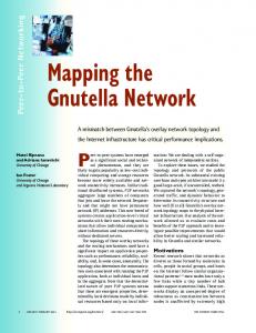
The performance analyses are based on three primary metrics: the network overhead, network latency, and packet delivery ratio. We believe that such metrics are necessary for determining the quality of any MCVE application. We investigate the impact of the underlying adhoc routing protocols and the network size on the aforementioned metrics. The network overhead, network latency, and packet delivery ratio are retrieved directly from the trace file, thanks to the Perl language. The packet delivery ratio is calculated as the total number of dropped packets divided by the total number of packets sent. Network latency is the average delay for data transfer from a sender node to a receiver. The average network overhead is measured in Kb/s and is defined as: (the total number of packets surfing in the network*packet size)/simulation time. In order to observe the improved performance of the developed system, we implemented three existing protocols; the mobile plain Gnutella [18], Mobile peer-to-peer MPP [25] and a Gnutella-based P2P System using cross-layer design for MANET (EGAN) [19]. The decision to compare our approach with the EGAN and MPP approaches stems from the degree of similarity between the cross-layer design and the method used to choose favorable peers for connection. This research direction is worthwhile since only a single routing protocol is used in the simulation scenarios in other works. The simulation results reveal that many of the conclusions drawn in previous protocols comparison studies are no longer true, given the traffic generated by the avatars movement in the VE and the limited number of logical connections for each node. The authors of [29] point out an interesting result; each routing protocol performs well in some scenarios but has weaknesses in others. However, Park et al [20] claim that Gnutella performs better when both a proactive ad-hoc routing protocol and a hierarchical node classification are used. In summary, with respect to different simulation scenarios, none of the previous works present the same opinion on the performance of routing protocols when Gnutella operates over MANETs. Let us now turn to our simulation experiments. As a first step, it is important to determine the appropriate values for both weight values w1 and w2, which are used to define the utility P values. We ran the simulations under different weight patterns: {[w1=1, w2= 0], [w1=0.9, w2= 0.1]… [w1=0, w2=1]}, using 50 wireless nodes in a low-mobility scenario. The appropriate weight pattern represents the lowest network overhead generated by the system. Fig. 6 shows the variations in network overhead as we vary the weight factors under the AODV, DSR, DSDV, HSR, and ZRP routing protocols. For ZRP we set the radius to 2 since it provides better performance. ZRP Simulation resells are omitted due to space lack.
AODV
10
DSDV
8
DSR 6
ZRP
4
HSR
2 0 W 1 W =0 W 1= 2= 0. 1 1 W W 2= 1= 0. 0. 9 2 W W 2= 1= 0. 0. 8 3 W W 2= 1= 0. 0. 7 4 W W 2= 1= 0. 0. 6 5 W W 2= 1= 0. 0. 5 6 W W 2= 1= 0. 0. 4 7 W W 2= 1= 0. 0. 3 8 W W 2= 1= 0. 0. 2 9 W 2= 0. W 1 1= 1 W 2= 0
7 PERFORMANCE EVALUATION
12
Network Overhead (Kb/s)
performance analyses are based on slow scenarios. Fast scenarios are given, so as to be more confident with simulation results and to present a complete research study.
Fig. 6. Approriete Values of w1 and w2 in slow scenario
Except for AODV, in a small-sized network (30 nodes), no matter what ad-hoc routing protocol is used. Our system generates a similar volume of messages. This is an expected result because the number of available peers is lower than the lower-bound connections nbMin; thus, the nodes continue discovering each other indefinitely without reaching a stable state. In addition, due to the link policy scheme, some nodes may reject the connection request. Nodes should therefore look for new neighboring nodes. HSR provide a better performance when the network size grows. Hierarchical routing appears to be more appropriate to our MCVE application.
7.1 Network Overhead With regard to network overhead, Fig. 7 indicates that our system was badly affected when implemented under AODV. When the network is overloaded, AODV generates large amount of message. 16
AODV
Network Overhead (Kb/s)
10
14
DSDV
12
HSR
10
DSR
8
ZRP
6 4 2 0 10
20
30
40
50
60
70
80
90
100
Network Size
Fig. 7. Average Network Overhead in a Slow Scenario
Except for AODV, in a small-sized network (30 nodes), no matter what ad-hoc routing protocol is used. Our system generates a similar volume of messages. This is an expected result because the number of available peers is lower than the lower-bound connections nbMin; thus, the nodes continue discovering each other indefinitely without reaching a stable state. In addition, due to the link policy scheme, some nodes may reject the connection request. Nodes should therefore look for new neighboring nodes. Hierarchical routing appears to be more appropriate to our MCVE application.
7.2 Mobility Effect The node’s speed determines how quickly its position changes in the network. The high mobility model yields to a higher network overhead and a corresponding drop in the delivery ratio. The reason for this is that, in lowmobility models, the network is more stable, compared with high-mobility models where the nodes are forced to move more often. To validate this hypothesis, we con-
A. BOUKERCHE ET AL.: A CROSS-LAYER APPROACH-BASED GNUTELLA FOR COLLABORATIVE VIRTUAL ENVIRONMENTS OVER MOBILE AD-HOC NETWORKS
Fig. 8. Average Network Overhead in the Fast Scenario
ZRP and DSDV appear to be less affected by mobility. For HSR, due to the cost of continuous updates in the physical partition, the network overhead is increased by about 25% compared to the low mobility scenarios. We focused our efforts on the low-mobility environments because the CVE application is considered a low-mobility application. However, the best ad-hoc routing protocol for fast scenarios is a subject of ongoing research. For the rest of the simulation experiments that will be mentioned below, we will use the low-mobility model.
7.3 Network Latency Network latency represents the average time duration for sending a message from one to another. Fig. 9 shows the network latency produced by our approach under the DSDV, ZRP, DSR, HSR, and AODV routing protocols.
Fig. 9. Network Latency in slow scenario
Regarding this metric, ZRP was badly affected. The reason for this increased delay is that, because ZRP implements two protocols Routing Protocol (IARP) and Interzone Routing Protocol (IERP), many packets are held in the buffer before being transmitted if inter-zone communication is required. The IERP packets are necessary for searching for a route. However, these packets may cause network congestion resulting in a decrease in network performance. Except for ZRP, the simulation results show a comparable amount of network latency. In large scenario, HSR exhibits the best network latency, followed by DSDV and then AODV. Update messages should be delivered to all users within an acceptable delay in order to maintain a sense of immersion in the virtual environment. Though the network latency requirement for any CVE application should be less than 400 ms [36], none of the created scenarios could reach such desired latency. Thus, future works should
focus more on this issue.
7.4 Packet Lost Ratio The packet lost ratio represents the ratio of the total messages dropped over the total number of messages surfing in the network. Fig. 10 shows the variation in the packet lost ratio against the network size under the AODV, ZRP, DSDV, HSR, and ZRP routing protocols. Percentage of Packet Lost (%)
ducted experiments with various network sizes (see Fig. 8). In contrast to our earlier experiment in Fig. 7, an increasing number of messages are generated because the network topology changes frequently.
0.6 AODV 0.5
DSDV
0.4
HSR DSR
0.3
ZRP 0.2 0.1 0 10
20
30
40
50
60
70
80
90
100
Network Size
Fig. 10. Packet Lost Ratio in Slow Scenario.
Using this metric HSR and DSDV outperform other routing protocols, with DSDV showing a slightly better performance. High network overhead is followed by a high packet loss percentage, since the network becomes overloaded as it is the case in AODV. Also ZRP does not support MCVE application, since it provides a high packet loss percentage. ZRP uses a caching scheme; many routes, thus, may become invalid. This may explain the significant amount of dropped packets in the ZRP experiments.
7.5 Degree of Node Connectivity The integration of the node states scheme in our developed system has led us to study the variations in the node connectivity degree metric during the simulation. Node stabilization is related to the network size. In Fig. 11, and 12, we set network size to 10 and 100 wireless nodes, respectively. As the previous network overhead results show, small scenarios provide an expectedly high network overhead because the number of available nodes is too small to fill up all of the slots in a node’s neighboring table. As the nodes remain in the connecting or initial states, they generate extra network overhead. In addition to the permanent discovery problem, low connectivity may also have an impact on network partition, since, in small networks, many nodes find themselves isolated.
Fig. 11. Connectivity Degree when Network Size Equal to 10.
As the network size increases, the degree of connectivity also increases; this is mainly caused by the increased number of available connections.
11
12
IEEE TRANSACTIONS ON PARALLEL AND DISTRIBUTED SYSTEMS, 2008-05-0193.R1
Fig. 12. Connectivity Degree when Network Size Equal 100
As shown in Fig. 12, no matter what routing protocol is used, we observe that the node’s degree of connectivity will not be affected. Except for ZRP, others protocols DSR, AODV, and DSR achieve comparable results. In large networks, the network stabilizes at around 100 seconds. Clearly, when network size is increased, the simulation time needed for network stabilization also decreases.
Clearly plain Gnutella is the worst affected. This confirms the claim that a straightforward implementation of Gnutella in mobile environment is not always satisfactory. Fig. 13 shows, that the average number of messages in our approach is about 5% less compared to MPP. MPP provides a better performance when the network size is small. However, when compared to EGAN, our approach diminishes the routing overhead by about 20 %. This is, perhaps, caused by the positive impact of the Gnutella Ultrapeer System and the link selection policy. B) Network Latency In this section, we want to study the impact of network latency on the implemented systems. The main factor that influences the performance of this metric is the flooding problem. Fig. 14 shows the network latency of the implemented approaches. The simulation results show the impact of the session routing context for our protocol.
7.6 Comparison with other Protocols As seen in the previous section, we focus mainly on the performance of our system. In this section, we implement three existing protocols: mobile plain Gnutella [18], MPP [25] and an Enhanced Gnutella for Ad-Hoc Networks (EGAN) [19] to compare them with our system. Mobile plain Gnutella is selected to show that a straightforward implementation of Gnutella is not satisfactory in MANETs. The choice of the EGAN scheme comes particularly from the desire to deal with the problem of inefficient connectivity in the overlay network formation process. MPP was chosen since it represents the most well known mobile application in the literature. In order to ensure a fair comparison with our system, we tune the Gnutella V0.6 [18] to support the four node states (Initial, Connecting, Stable, and Full). CVE is a network-delay- and bandwidth-sensitive application; therefore, we select routing overhead, network latency and packet delivery ratio as the main metrics for our comparisons. In this simulation, our system uses HSR, plain Gnutella and EGAN uses AODV, while MPP uses EDSR [25]. A) Network Overhead The implemented systems introduced distinguishing amounts of routing overhead when network size increases. Fig. 13 shows the behavior of the network overhead. The simulation results display the impact of the network structure and the link selection policy on this metric.
Fig. 14. Network Latency Comparison
With regard to this metric, Fig. 14 indicates that our protocol provides a slight improvement over MPP. This improvement is due to the integration of session ID for queries filtering in the network layer. Network latency in plain Gnutella is very high; this is caused by the incremented network overhead generated by plain Gnutella. C) Delivery Packet Ratio In terms of the packet delivery ratio metric, the reason for the low delivery ratio is usually caused from the network congestion and the higher network overhead. Fig. 15 shows the packet delivery ratio for the implemented systems when we increase network size. The simulation results indicate that the packet delivery ratio is optimal when the network size is relatively small.
Fig. 15. Packet Delivery Ratio Comparison
Fig. 13. Network Overhead Comparison
Our system MOG-CVE and MPP are the systems that produce the highest packet delivery ratio. The plain Gnutella network was badly affected. This is concurrent with the previously described network overhead results shown in Fig. 13. In EGAN, due to node mobility, the cached
A. BOUKERCHE ET AL.: A CROSS-LAYER APPROACH-BASED GNUTELLA FOR COLLABORATIVE VIRTUAL ENVIRONMENTS OVER MOBILE AD-HOC NETWORKS
information during the bootstrapping process may become outdated, and, thus, many packets are dropped.
8 CONCLUSION In this paper, we present a cross-layer approach over Gnutella network to support mobile collaborative virtual environment. The protocol provides an efficient rule-based discovery process using specific link selection policy and user’s collaboration context. Broadcast messages are reduced in this topology by using a node states mechanism and Gnutella Ultrapeer System. The advantage of this protocol is that the overlay network can remain static even when there is a change in the physical layer due to node mobility. Obtained simulation results has shown that our system reduce significantly the network overhead and the network latency by 20% and 10% respectively when compared to mobile enhanced Gnutella. As a future work, we are intended to further improve our system performance, so that users can subscribe in multiple sessions.
[11]
[12]
[13]
[14]
[15]
[16]
REFERENCES [1]
A. Bejan, R. Lawrence. "Peer-to-peer cooperative driving". International Symposium on Computer and Information Sciences, USA, Oct 2002, pp. 259-264. [2] A. Boukerche, A. Roy , and N. Thomas. "Dynamic Grid-Based Multicast Group Assignment in Data Distributed Management". Proc. 4th IEEE International Workshop on Distributed Simulation and Real-Time Applications, USA, 2000, pp. 47-54. [3] A. Boukerche, R. Araujo, and M. Laffranchi. "Multiuser 3D Virtual Simulation Environments Support in the Gnutella Peerto-Peer Network". Journal on Parallel Distributed. Computing. Vol 65, Issue 11, 2005, pp. 1462-1469. [4] A. Boukerche, A. Zarrad, and R. Araujo "A Heterogeneous Network Architecture based Gnutella for Mobile Emergency Preparedness Applications". Proc. Conference Computer Systems and Applications, 2008, Katar, pp: 1064-1069. [5] A. Boukerche, A. Zarrad, R. de Araujo. " A Performance Evaluation of an Optimized Caching Protocol for the Mobile Gnutella based Network to Support Distributed Collaborative Virtual Environments". Proc. Local Computer Networks, Spain, 2007: pp. 207-209. [6] A. Boukerche, A. Zarrad, R. de Araujo. "A Smart Gnutella Overlay Formation for Collaborative Virtual Environments over Mobile Ad-Hoc Networks". Proc. of the 10th IEEE international symposium on Distributed Simulation and Real-Time Applications, Canada 2006, pp: 143 – 156. [7] A. Ephremides, J. Wieselthier, and D. Baker. "A design concept for reliable mobile radio network with frequency hopping signaling". Proc. of IEEE 75, 1987, pp: 56-73. [8] A. Huhtonen. "Comparing AODV and OLSR Routing Protocols". 2004. [9] A. Iwata, C. Chiang, G.Pei, M. Gerla, and W. Chen. " Scalable Routing Strategies for Ad-hoc Wireless Networks". Journal on Selected Areas in Communications, Special Issue on Ad-Hoc Networks, Vol 17, Issue 8, 1999, pp: 1369-1379. [10] A. Klemm, C. Lindemann, and O. Waldhorst. “Peer-to-Peer
[17] [18] [19]
[20]
[21]
[22]
[23]
[24] [25]
[26]
[27] [28] [29]
Computing in Mobile Ad Hoc Networks”. Performance Tools and Applications to Networked Systems, E. Gelenbe and M. Calzarossa (Eds.), LNCS 2965, Springer-Verlag, 2004, pp. 187– 208. A. Rowstron and P. Druschel. “Pastry: Scalable, distributed object location and routing for large-scale peer-to-peer systems”. IFIP/ACM International Conference on Distributed Systems Platforms, Germany, 2001, pp. 329-350. B. Oliveira, L. Guimaraes Siqueira, and I. Ferreira Loureiro. "Evaluation of ad-hoc routing protocols under a peer-to-peer application". Proc. Wireless Communications and Networking, 2003, USA, pp:1143-1148. B. Tang, Z. Zhou, A. Kashyap, and T. Chiueh. "An Integrated Approach for P2P File Sharing on Multi-hop Wireless Networks". Proc. of the IEEE Int. Conference on Wireless and Mobile Computing, Networking and Communication, 2005, Canada, pp: .268–274. B. Zhao, J. Kubiatowicz, and A. Joseph. "Tapestry: An infrastructure for fault-resilient wide-area location and routing". Technical Report UCB//CSD-01-1141, U. C. Berkeley, 2001. D. Johnson, D. Maltz, Y. Hu, and J. Jetcheva. "The dynamic source routing protocol for mobile ad hoc networks". Internet Draft, Internet Engineering Task Force, 2001. http://www.ietf.org/internetdrafts/draft-ietf G. Ding, and B. Bhargava. "Peer-to-peer File-sharing over Mobile Ad hoc Networks". Second IEEE Annual Conference on Pervasive Computing and Communications Workshops, 2004, USA, pp. 104-108. Gnutella Homepage: http://www.gnutella.com. Gnutella protocol v0.6. Homepage (2008): http://rfcgnutella.sourceforge.net/developer/testing/index.html. H. Choi, H. Park, and M. Woo. "An Enhanced Gnutella for AdHoc Networks". International Conference on Systems and Networks Communicatio, USA, 2006, pp.3-13. H.Choi, H.Park, and M.Woo "Performance Analysis of Peer-toPeer Application in Ad-hoc Networks". Proceddings ITST, USA, 2005, pp. 49-52. H. Park, W. Kim, and M. Woo. "A Gnutella-based P2P System Using Cross-Layer Design for MANET". Proc. of world academy of science, Engineering and Technology, Vol 22, 2007, ISSN 1307-6884. H.Pucha, M.Das, Y.Charli. "The performance impact of traffic patterns on routing protocols in mobile ad hoc networks". Proc. of the 7th ACM international symposium on Modeling, analysis and simulation of wireless and mobile systems, USA, 2004, pp. 211 – 219. H. Zhang, A. Goel, and R. Govindan. "Incrementally Improving Lookup Latency in Distributed Hash Table Systems". Proc. of the ACM SIGMETRICS international conference on Measurement and modeling of computer systems, USA, 2003, pp.114125. IETF Working Group MANET (2008): http://www.ietf.org/html.charters/manet-charter.htm I. Gruber, R. Schollmeier, and W. Kellerer. "Performance Evaluation of the Mobile Peer-to-Peer Service". Proc. of the IEEE International Symposium on Cluster Computing and the Grid. USA, 2004, pp. 363-371. I. Stoica, R. Morris, D. Karger, M. Kaashoek, and H. Balakrishnan. "Chord: A Scalable Peer-to-Peer Lookup Protocol for Internet Applications". Proc. IEEE/ACM Transactions on Networking. USA, 2003, pp.17-32. JXTA Homepage (2008): https://jxta.dev.java.net/ Kazaa Homepage (2007): www.kazaa.com L . Barbosa, I. Guimaraes, and A. Ferreira "Evaluation of adhoc routing protocols under a peer-to-peer application". Proc. Wireless Communications and Networking WCNC, 2003. USA, pp. 1143 – 1148.
13
14
IEEE TRANSACTIONS ON PARALLEL AND DISTRIBUTED SYSTEMS, 2008-05-0193.R1
[30] L. Hao-Jun, Q. Fei-Yue, and L. Yu-Jun. "Research on Mechanism Optimization of ZRP Cache Information Processing in Mobile Ad Hoc Network". Proc. Wireless Communications, Networking and Mobile Computing, 2007. USA, pp:1593 – 1596. [31] M. Conti, E. Gregori, and G. Turi. “A cross-layer optimization of Gnutella for mobile ad hoc networks“. Proc. 6th ACM international symposium on Mobile ad hoc networking and computing. USA, 2005. pp. 343-354. [32] M. Oliveira, J. Crowcroft, and M. Slater. "An Innovative Design Approach to Build Virtual Environment Systems". Proc. of the workshop on Virtual environments. Swzland, 2003, pp. 143-151. [33] Morpheus Homepage (2008): www.morpheus.com [34] M. Peterson "Learning interaction in an Avatar-based Virtual Environment: a Preliminary Study". Journal Pacific Association for Computer Assisted Language Learning, Vol 1 No. 1, 2005, pp: 29-40. [35] M. Srivatsa, B. Gedik, and Ling Liu, "Large Scaling Unstructured Peer-to-Peer Networks with Heterogeneity-Aware Topology and Routing". IEEE Transactions on Parallel and Distributed Systems. Vol 17. Issue 11, USA, 2006, pp. 1277-1293. [36] M. Wloka. “Lag in Multiprocessor VR“. Teleoperators and Virtual Environments (MIT Press), Vol. 4. 1995, pp. 50-63. [37] Network simulator ns-2 home page (2008): http://www.isi.edu/nsnam/ns/ [38] S.PalChaudhuri, J. Le Boudec, and M. Vojnovic. "Perfect simulations for random trip mobility models". Proc.. 38th AnnualSimulation Symposium, 2005, USA , pp:72-79. [39] S. Ratnasamy, P. Francis, M. Handley, R. Karp, and S. Shenker. "A scalable content-addressable network". Proc. on Applications, technologies, architectures, and protocols for computer communications. USA, 2001, pp. 161-172. [40] S. Zhao, D. Stutzbach, and R. Rejaie. "Characterizing Files in the modern Gnutella Network: A Measurement Study". Proc. of SPIE Multimedia Computing and Networking. USA, 2006, pp. 113-126. [41] Wikipedia encyclopedia home page (2009):http://en.wikipedia.org/wiki/Orders_of_magnitude_(s peed) [42] Z. Zhange, Y, Liu and L. Xiao. "Dynamic layer management in super-peer architectures". International Conference on Parallel Processing, USA, 2004, pp: 29-36.
Glinski Research Excellence Award. He is a Co-Founder of QShine Int'l Conference, on Quality of Service for Wireless/Wired Heterogeneous Networks (QShine 2004), served as a General Chair for the 8th ACM/IEEE Symposium on modeling, analysis and simulaltion of wireless and mobile systems, and the 9th ACM/IEEE Symposium on distributed simulation and realt time-application, a Program Chair for ACM Workshop on QoS and Securuty for Wireless and Mobile networks, ACM/IFIPS Europar 2002 Conference, IEEE/SCS Annual Simulation Symposium ANNS 2002, ACM WWW'02, IEEE MWCN 2002, IEEE/ACM MASCOTS 2002, IEEE Wireless Local Networks WLN 03-04; IEEE WMAN 04-05, ACM MSWiM 98-99, and TPC member of numerous IEEE and ACM sponsored conferences. He served as a Guest Editor for the Journal of Parallel and Distributed Computying (JPDC) (Special Issue for Routing for mobile Ad hoc, Specail Issue for wireless communication and mobile computing, Special Issue for mobile ad hoc networking and computing), and ACM/kluwer Wireless Networks and ACM/Kluwer Mobile Networks Applications, and the Journal of Wireless Communication and Mobile Computing. He serves as Vice General Chair for the 3rd IEEE Distributed Computing for Sensor Networks (DCOSS) Conference 2007, as Program Co-Chair for Globecom 2007 and 2008 Symposium on Wireless Ad Hoc and Sensor Networks and a Finance Chair for ACM Multimedia 2008. Dr. A. Boukerche serves as an Associate Editor for ACM/Springer Wireless Networks, IEEE Wireless Communication Magazine, IEEE Transaction on Parallel and Distributed Systems, Wiley In't Journal of Wireless Communication and Mobile Computing, Wiley's Security and Communication Network Journal, Wiley's Pervasive and Mobile Computing Journal, the Elsevier's Journal of Parallel and Distributed Computing, and the SCS Transactions on Simulation. He also serves as a Steering Committee Chair for the ACM Modeling, Analysis and Simulation for Wireless and Mobile Systems Symposium, the ACM Workshop on Performance Evaluation of Wireless Ad Hoc, Sensor, and Ubiquitous Networks and the IEEE/ACM Distributed Simulation and Real-Time Applications Symposium (DS-RT).
Azzedine. Boukerche is a Full Professor and holds a Canada Research Chair position at the University of Ottawa. He is the Founding Director of PARADISE Research Laboratory at uOttawa. Prior to this, he held a Faculty position at the University of North Texas, USA, and he was working as a Senior Scientist at the Simulation Sciences Division, Metron Corporation located in San Diego. He was also employed as a Faculty at the School of Computer Science McGill University, and taught at Polytechnic of Montreal. He spent a year at the JPL/NASA-California Institute of Technology where he contributed to a project centered about the specification and verification of the software used to control interplanetary spacecraft operated by JPL/NASA Laboratory. His current research interests include wireless ad hoc and sensor networks, wireless networks, mobile and pervasive computing, wireless multimedia, QoS service provisioning, peformance evaluation and modeling of large-scale distributed systems, distributed computing, large-scale distributed interactive simulation, and parallel discrete event simulation. Dr. Boukerche has published several research papers in these areas. He was the recipient of the Best Research Paper Award at IEEE/ACM PADS'97, and ACM MobiWac'06 the recipient of the 3rd National Award for Telecommunication Software 1999 for his work on a distributed security systems on mobile phone operations, and has been nominated for the best Paper Award at the IEEE/ACM PADS'99, and ACM MSWiM 2001. Dr. A. Boukerche is a holder of an Ontario Early Research Excellence Award (previously known as Premier of Ontario Research Excellence Award), Ontario Distinguished Researcher Award, and
Regina B. Araujo is an Associate Professor at the Computer Science Department of Federal University of Sao Carlos (UFSCar), Brazil. Prof. Araujo research interests are wireless networks, distributed simulations, context-aware computing and advanced interfaces with application focus on emergency management. She is a Post-Doc Fellow at PARADISE Research Laboratory, Ottawa University, and Founding Director of the Networked Virtual Reality Laboratory at UFSCar in Brazil. She is UFSCar General Secretary of Informatics and Sao Carlos Research and Education Metropolitan Network Management Committee Coordinator. Prof. Araujo has served as TPC member in several conferences on wireless networks and distributed systems (MSWIM, ICPP, P2MNET, Q2SWinet, WIMOB, ISCC, ICCCN, Globecom) and as general chair for WMUNEP conference on Wireless Multimedia Networking and comPuting.
Anis. Zarrad is a Ph.D. condidate in School of Information Technology and Engineering (SITE), University of Ottawa. He received his B.S. in 2002 and his M.S. in 2004, both in Computer science. His reserch interests include collabaotative virtuelle emvioment, wireless networks and peer-to-peer netwoks. His PhD thesis is related to the design of protocols for mobile collaborative virtual environement. This work is part of his PhD thesis.