between component-based software engineering and data management by ... Automotive Data Dictionary [6, 17, 22], have been devel- oped in an effort to get ...
A Data-Entity Approach for Component-Based Real-Time Embedded Systems Development.∗ Andreas Hjertström, Dag Nyström, Mikael Sjödin Mälardalen Real-Time Research Centre, Västerås, Sweden {andreas.hjertstrom, dag.nystrom, mikael.sjodin}@mdh.se
Abstract In this paper the data-entity approach for efficient design-time management of run-time data in componentbased real-time embedded systems is presented. The approach formalizes the concept of a data entity which enable design-time modeling, management, documentation and analysis of run-time data items. Previous studies on data management for embedded real-time systems show that current data management techniques are not adequate, and therefore impose unnecessary costs and quality problems during system development. It is our conclusion that data management needs to be incorporated as an integral part of the development of the entire system architecture. Therefore, we propose an approach where run-time data is acknowledged as first class objects during development with proper documentation and where properties such as usage, validity and dependency can be modeled. In this way we can increase the knowledge and understanding of the system. The approach also allows analysis of data dependencies, type matching, and redundancy early in the development phase as well as in existing systems.
1 Introduction We present the data-entity approach for efficient designtime management of run-time data in embedded real-time systems. We propose methods, techniques and tools that allow modeling of data into a design entity in the overall software architecture. This enables developers to keep track of system data, retrieve accurate documentation and perform early analysis on data items. The goal is to achieve higher software quality, lower development costs, and to provide higher degree of control over the software evolution process. We show how our approach can be coupled to a development environment for component-based software engineering (CBSE), thus bridging the gap between CBSE and traditional data management. For example, it bridges ∗ This work is supported by the Swedish Foundation for Strategic Research within the PROGRESS Centre for Predictable Embedded Software Systems.
the encapsulation paradigm of CBSE and the blackboard paradigm of traditional data-management techniques. Our approach primarily targets data intensive and complex embedded real-time systems with a large degree of control functions, such as vehicular, industrial and robotic control-systems. These domains, and also software intensive embedded systems in general, has in recent years become increasingly complex; up to the point that system development, evolution and maintenance is becoming hard to handle, with corresponding decreases in quality and increases of costs [11]. For instance, the cost for development of electronics in for instance high-end vehicles, have increased to more than 40% of the total development cost and systems contain more than 70 electronic control-units (ECUs) and up to 2500 signals [1, 8, 9]. In an effort to handle the increasing complexity of embedded real-time systems, various tools and techniques, such as component-based software engineering [5, 10], real-time data management [13, 15], and network bus management [4], has previously been introduced. While these techniques and tools have the common aim to reduce software complexity, they target different areas of system complexity. CBSE, for example, targets encapsulation of functionality into software components that are reusable entities. Components can be mounted together as building blocks, with a possibility to maintain and improve systems by replacing individual components [5]. On the other hand, realtime data management, e.g. database technologies, target data produced and consumed by functions by providing uniform storage and data access, concurrency-control, temporal consistency, and overload and transaction management. Network management in turn, aim to handle the increasing amount of data that is distributed throughout ECUs in the system and, e.g. manage the temporal behavior of distributed data. However, despite their common aim of reducing complexity, these techniques in some cases have contradicting means of achieving their goals. For example, the requirement of information hiding and component data interfacing
in component-based systems might conflict with the common blackboard data storage architecture using real-time databases. To overcome these contradictions, it is our belief that data management must be made to be an integral part of the design environment as an architectural view. It is also becoming additionally important to consider data freshness in embedded real-time systems as have been done within the real-time database community [23]. The main contributions of this paper include: • We introduce the concept of a data entity to encapsulate all metadata, such as documentation, type, dependencies, and real-time properties concerning a run-time data item in a system. The data-entity approach provides designers with an additional architectural view which allows for data searching, dependency visualization, and documentation extraction. • The data-entity approach provide techniques which are tightly coupled with component-based software engineering. • Our approach allows properties of data to be analyzed any time during the development process. A model of data entities can be constructed before development commences, thus giving the possibility to provide early feedback to designers about consistency and type compatibility. Alternatively, a model can be extracted from existing designs, allowing analysis of redundancies and providing a base for system evolution. • The data-entity architectural view complements other architectural views, such as component-based architectural views, without violating paradigms such as information-hiding, encapsulation and reuse. • Finally, we have realized this approach by implementing it into a tool-suite, using the existing component model ProCom [3] that also offers a development environment. The tool includes data entity editors as well as a number of analysis tools. The rest of this paper is structured as follows; in section 2, we present background and motivation for the approach. We also present four specific problems that our approach addresses. In section 3, a definition of the data entity is presented and the data entity approach is discussed in section 4. Further, in section 5, we describe the ProCom component-model which is used in our data entity tool-suite, presented in section 6. An example of how the data entity tool-suite can be used is presented in section 7. Finally, the paper is concluded in section 8.
2 Background and Motivation The aim of our approach is to bridge the current gap between component-based software engineering and data management by extending the architectural views with a
data-centric view that allow run-time data to be modeled, viewed and analyzed. Current system design techniques emphasize the design of components and functions, while often neglecting modeling of flow and dependencies of runtime data. A recent study of data management at a number of companies producing industrial and vehicular embedded real-time systems clearly showed that this gap is becoming increasingly important to bridge, and that current designtechniques are not adequate [11]. The study showed that documentation and structured management of internal ECU data is currently almost nonexistent, and most often dependent on single individual persons. Traditionally, the complexity of an ECU has been low enough so that it has been possible for a single expert to have a fairly good knowledge of the entire architecture. However recently, companies are experiencing that even internal ECU data complexity is growing too large for a single person to manage. This has led to a need for a structured data management with adequate tool support for system data. A similar development took place within the vehicular domain in the late 1990s, when the industry took a technological leap with the introduction of bus-management tools, such as the Volcano tool [4]. By that time, the distributed vehicular systems had grown so complex that it was no longer feasible to manage bus packet allocation and network data-flow without proper tool support. It is pointed out in the study, that there is a clear need for a similar technological leap for overall system data management. 2.1 Problem Formulation The case study [11] identifies a number of problems related to poor data management in practice today. In this paper, four of these problems are specifically addressed. Addressed problems: P1 ECU signals and states are, in many cases, not managed and documented at all, companies often are entirely dependent of the know-how of single individual experts P2 The lack of structured management and documentation has in several cases led to poor routines for adding, deleting and managing data. Often a "hands-off" approach is used where currently functioning subsystems are left untouched when adding additional functionality, since reuse of existing data is considered too risky due to lack of knowledge of their current usage. P3 Some companies calculate with up to 15% overhead for unused and stale data being produced. It is considered too difficult to establish if and how these stale data are being consumed elsewhere in the system. P4 A lack of adequate tool support to model, visualize and analyze system data.
To further complicate matters, companies developing safety-critical systems are becoming increasingly bound to new regulations, such as the IEC 61508 [12]. These regulations enforce stronger demands on development and documentation. As an example, for data management it is recommended, even on lower safety levels, not to have stale data or data continuously updated without being used. Companies lacking techniques for adequate data management and proper documentation will be faced with a difficult task to meet these demands. 2.2 Related Work Several tools within code analysis and code visualization have been developed to be able to explore data-flow and how functions are connected [2, 21]. These are however mainly built to interpret existing code and not focusing on high level data management during development. The increase in complexity and the amount of signals used within ECU development has also been addressed within the data modeling area. A number of data dictionary tools such as dSpace Data Dictionary, SimuQuest UniPhi and Visu-IT Automotive Data Dictionary [6, 17, 22], have been developed in an effort to get an overall view of the systems signals as well as structured labeling and project management. These tools are tightly coupled with MATLAB/Simulink and MATLAB/Targetlink [20] which is line with current state-of-practice. However none of these tools specifically target CBSE. dSpace Data Dictionary does however additionally provide techniques for managing AUTOSAR [10] property specifications. Furthermore, non of these tools target high-level data management where data can be modeled, analyzed and visualized in an early phase of development. To confront the intricacy of embedded system development of today and tomorrow, CBSE will play a more central part. However, supporting tools, specifically targeting component-based systems, needs to be developed to support the technological leap needed within data management. Common for both CBSE and the data entity approach is that they aim to assemble and design systems at a higher level by encapsulating information and functionality into components or entities. The aim with our approach is to add to the functionality of the above stated tools. In our approach, data is seen as a component/entity in the development strategy. This allows data to be modeled separately with a possibility to perform early analysis such as relative validity. It also allows system architects and developers to graphically view data dependencies, similar as components can viewed during system development. This information can then be connected to the data flow in the component model and used as input to the system architect when developing the system.
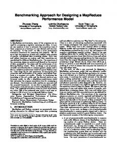
Figure 1. Data Entity Description Model
3 The Data Entity In this section we will first introduce the concept of data entity. Secondly we present how data entities can be used and analyzed, both in an early phase of development and for already developed systems. 3.1 Data Entity Definition The concept of a data entity that encapsulates all metadata is the basis of our approach. A data entity is a compilation of knowledge for each data item in the system. A data entity can be defined completely separate from the development of components and functions. This enable developers to set up a system with data entities based on application requirements and perform early analysis even before the producers or consumers of the data are developed. The information collected by data entities are also valuable for developers and system architects when redesigning or maintaining systems. Another important feature is that since a data entity is completely separated from its producers and the consumers, it persists in the system regardless of any component, function or design changes. A data entity consists of the following metadata (illustrated in Figure 1): • Data Entity, is a top level container describing the overall information of a set of data variants. Data entities are created to aid developers with problem P1 and P2, by elevating the importance level of data during development and maintenance. Required information is associated with the data entity and its data variants, enabling it to persist on its own during all the phases of a system life-cycle. As an example, a data entity could be vehicleSpeed. The data entity also includes a top level description to facilitate for a developer in need of high level information. • Data Variant, is the entity that developers will come in closer contact with and consist of properties, requirements, dependencies and documentation. A data variant can be of any type, size or have any resolution. To continue our example from above where the top level data entity is vehicleSpeed, we can add a number of variants.
For example vehicleSpeedSensorValue, vehicleSpeedInt, vehicleSpeedDouble, vehicleSpeedMph and vehicleSpeedKmh. Each of these variants with their own properties, requirements, dependencies and documentation. A data variant could for instance be specified with consumer requirements, but without any existing producer properties. The requirements then can later be used as input when searching for an existing producer or when creating a new producer. • Data Producers, the set of components producing the given data variant. • Data Consumers, the set of components consuming the given data variant.
• Data Flow Analysis. This analysis show producers and consumers of a specific data entity variant. It is able to detect unproduced as well as unconsumed data, and is thereby directly addressing problem P2, P3 and P4. The output of this analysis can the be forwarded to system architecture tools to expose which components that would be affected by a change to a data entity. • Data Dependency Analysis. Data dependency analysis can facilitate for developers and aid with problem P3, by providing information about which producers and consumers that based on their properties and requirements are dependent on each other regarding temporal behavior and precedence relations.
• Data Variant Properties, is either an existing producer’s property or a set of properties that is based on the consumer requirements. If there is no existing producer, these properties can be used as requirements by the system architect. Examples of properties are: name, type, size, initial value, minimal value, maximal value and frequency. • Data Variant Requirements, are directly related to the requirements of a consumer. These requirements can be matched against producer properties or be the source for the producer properties. Example requirements are: frequency, accuracy and timing consistency parameters. • Data Variant Dependencies, enables a possibility to see which data entities that is dependent on each other regarding for instance temporal consistency and precedence relations.
• Type Check Analysis. Data types from the producer properties and the requirements of the consumer is analyzed to make sure that there is a match.
• Data Variant Documentation, gives the developer an opportunity to describe and document the specifics of each data variant. • Keywords, Data entities and data variants can be tagged with keywords to facilitate a better overview and give developers additional benefits where a data entity or a data variant with related information can be searched for using keywords. Since companies can have their own unique naming ontologies, keywords can be adapted to suite a specific need. As an example, if a developer is interested a data entity regarding the vehicle speed with a certain type and resolution. He/she can then search using the keyword, for instance "speed", to receive all speed related signals. From there, find the appropriate data entity and its different data variants.
• Relative Validity Analysis. Relative validity is a measurement of how closely two interacting data entity variants have been produced [14]. Even though both data might be absolute consistent, they might be relative inconsistent, which indicate that any derived data would be considered inconsistent. Additional research on methods, tools and techniques for how to find the relative data dependency between several execution chains and their end-to-end deadline is needed in order to guarantee the relative data freshness demanded by a consuming component. To achieve this, we propose an extension of [7], with a formal framework for relative dependency. Similar to absolute validity, properties from producers are analyzed to see if the requirements of the consumers are achieved.
3.2 Data Entity Analysis Using the information contained in the data entities, data-entity analysis is possible during the entire development process, even in the cases where producers or consumers are yet undefined. The approach open up for a number of possible analysis methods such as:
• Resolution/Domain Analysis. Matches the data resolution and possible data domains to the connected producers and consumers. • Absolute Validity Analysis. Absolute validity is a measurement of data freshness [18]. An absolute validity interval can be specified for a data entity variant, which specifies the maximum age a data can have before being considered stale. The importance of knowing the end-to-end path delay i.e. data freshness, in an execution chain, especially within the automotive systems domain, have been identified in previous work, such as [7]. Properties from producers are analyzed to see if the requirements of the consumers are achieved.
4 The Data Entity Approach The data entity approach provides designers with an additional architectural view, the data architectural view. This view allows data to be modeled and analyzed from a data management perspective during development and maintenance of component-based embedded systems.
System Requirements
Component Architecture Development
Component Development Tool
System Analysis Tool System Architecture Tool
Legend Process
Tool
Data
Data Architecture Development
Central Database
Data Modeling Tool
Data Analysis Tool
Data Entities
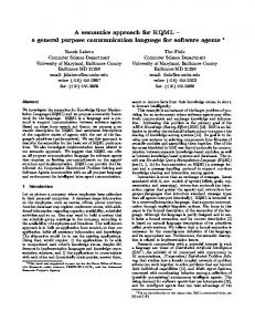
Figure 2. The data entity approach
Figure 2 show our proposed data entity approach (righthand side). The figure illustrates how our approach complements the traditional component-based design approach (left-hand side). The central database in the middle of the figure acts as the communicating link between the two approaches as well as the main storage for information. In the data modeling tool, data entities can be created, retrieved and modified. Furthermore, they can be associated with design entities such as message channels created from the ProCom component architecture development [3]. The data analysis tool extracts data and data producer properties based on the requirements placed upon the data from the data consumers. These properties could then be propagated to a system architecture tool as component requirements on the components producing the data. It can also be used as input to system synthesis and scheduling tools. Furthermore, the data analysis tool could provide graphical visualization of all data dependencies, both with respect to data producers and consumers for a certain data, but also visualize dependencies between different data, such as relative consistency and precedence relations. System design using the data entity approach can start from data architecture design, from system architecture design, or from a combination of both. If for example, in the early stages of an iterative design process, a set of components that provide a given function is designed, it is often the case that the input signals to this function is not yet defined, and therefore left unconnected in a functional design. If these unconnected data signals are modeled using a data entity, the data analysis tool can be used to derive required properties of this data, which can later be sent as input to a system architect tool as component requirements of the component that is later connected as producer of this data. On the other hand, consider that a commercial, off-the-shelf (COTS), component that provides certain functionality is integrated in a system architecture tool, and that component produces a set of signals of which a subset is currently not needed, these data can still be modeled, and made searchable for future needs. In this case, the data analysis tool can be used to derive the properties of this data.
Also in management and extension of existing systems, the data modeling tool can be used to search for existing data that might be used as producers for the new functionality. The requirements for the new functionality can then be matched towards the existing properties and requirements of the other consumers of the data, to determine whether or not the data can be used for this functionality. This solves the "hands off" problem presented in problem P2.
5 The ProCom Component Model The ProCom component model aims at addressing key concerns in the development of control-intensive distributed embedded systems. ProCom provides a two-layer component model, and distinguishes a component model used for modeling independent distributed components with complex functionality (called ProSys) and a component model used for modeling smaller parts of control functionality (called ProSave). In this paper we only focus on the more large scale ProSys. The complete specification of ProCom is available in [3]. In ProSys, a system is modeled as a collection of concurrent, communicating subsystems. Distribution is modeled explicitly; meaning that the physical location of each subsystem is not visible in the model. Composite subsystems can be built out of other subsystems, ProSys is an hierarchical component model. This hierarchy ends with the so-called primitive subsystems, which are either subsystems coming from the ProSave layer or non-decomposable units of implementation (such as COTS or legacy subsystems) with wrappers to enable compositions with other subsystems. From a CBSE perspective, subsystems are the components of the ProSys layer, i.e., they are design or implementation units that can be developed independently, stored in a repository and reused in multiple applications.
Figure 3. ProSys Component Model For data-management purposes, the communication between subsystems is the most interesting issue. The communication is based on asynchronous message passing, allowing location transparency in communication. A subsystem is specified by typed input and output message ports, expressing what type of messages the subsystem receives and sends. The specification also includes attributes and models related to functionality, reliability, timing and resource usage, to be used in analysis and verification throughout the development process. The list of models and attributes used is not fixed and can be extended.
Message ports are connected though message channels. A message channel is an explicit design entity representing a piece of information that is of interest to one or more subsystems. Figure 3 shows an example with three subsystems connected via one message channel. The message channels make it possible to express that a particular piece of shared data will be required in the system, before any producer or receiver of this data has been defined. Also, information about shared data such as precision, format, etc. can be associated with the message channel instead of with the message port where it is produced or consumed. That way, this information can remain in the design even if, for example, the producer is replaced by another subsystem.
6 Embedded Data Commander Tool-Suite The embedded data commander (EDC) is a tool-suite that implements the data entity approach for the ProSys component-model. The tool-suite, which so far is implemented in the Eclipse framework [19] as a stand alone application that provides a tight integration between Data Entities and ProSys message channels. The tool-suite, consists of four main parts: • The Data Collection Center (DCC), which is the common database that holds all information regarding data entities, channels, requirements and subsystems. • The Data Entity Navigator (DEN), which is the main application and modeling tool where data entities are administrated. • The Data Analysis Tool (DAT), which performs data analysis on data variants and subsystems. • The Channel Connection Tool (CCT), which is the interface tool towards the ProCom tool-suite. The Data Collection Center, DCC is the central database that all EDC tools communicates through. A commercial relational SQL database is used to implement the DCC [13], allowing multiple tools to concurrently access the DCC enabling use of the tool-suite in large development projects. The DCC consists of three main storage objects (Figure 4), the data entity-, the message channel- and the system description-object. The Data Entity Navigator, DEN is the main application of EDC. In DEN developers can create, retrieve or modify data entities. It is also in DEN developers can manage data entity properties, requirements, dependencies, description and documentation. An important feature in DEN is that developers can view to which other channels and component a data variant is connected, thereby providing valuable information regarding dependencies and an opportunity to navigate between data entities and related subsystems to access information.
Subsystem
Data Collec�on Center (DCC) Database
System Descrip�on Requirements
Message Channel
Data En�ty Variant
Requirements
Data En�ty
Ports
Documenta�on
Proper�es
Figure 4. DCC data model description
The information available in the DEN can also be filtered and divided into sections to facilitate for developers to find the appropriate information. It would also be possible to extend the tool to produce custom-tailored reports containing only the necessary information for its specific purpose. The Data Analysis Tool, DAT, handles all analysis regarding data entities variants. The current version of the tool support analysis on data flow, type check, resolution and domain analysis but will be extended to support absolute-, and relative-validity analysis. The Channel Connection Tool, CCT, is the connection point between the data entity and the ProCom tool-suite. Since the ProCom tools has been separately developed, a tool to extract architectural information and message channel information was needed. Yaw sensor
YawAngle
Lateral accelera�on sensor
LateralAccel
Steering wheel angle sensor
SteeringAngle
Stability Control System
Thro�leAdjust
BreaksPressure
LfWheelSpeed
Wheels Speed Sensor
RfWheelSpeed LrWheelSpeed RrWheelSpeed
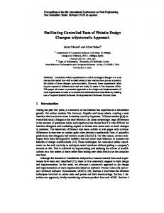
Figure 5. Existing ProSys Stability Control System application
7 Use Case To illustrate our ideas, this section will describe two simple scenarios. The first is, expanding an existing system and the second, verification of the consistency between dataproducers and consumer in connection with system validation. This example is illustrated using the concept of data entities and the EDC tool together with ProCom. 7.1 Expanding an Existing System This example starts with an existing vehicle application which has already been developed. A part of this system [16] is illustrated in Figure 5. We now face a situa-
tion where we should add additional functionality. The new functionality demand an additional component, called C_1, to be added that requires two signals as input. To make it easier for the developer when adding these signals and additional functionality the EDC tool can be used to facilitate reuse of existing signals (if suitable signals exists) to avoid redundancy and also to gain knowledge about possible dependencies between data entities. Yaw sensor
YawAngle
Lateral accelera�on sensor
LateralAccel
Steering wheel angle sensor
SteeringAngle
When the system modifications are completed, a validation of the whole system should be performed. However in this example we only focus on the newly introduced component C_1. A series of analysis can be performed to validate that the requirements of C_1 is fulfilled. Data variant SteeringAngle VehicleSpeedMph
Type Int Int
Size 16 16
Unit Arcsec MPH
P(ms) 20 10
Figure 7. Producer properties. Stability Control System
Thro�leAdjust
BreaksPressure
LrWheelSpeed RlWheelSpeed RrWheelSpeed
Vehicle Speed
C_1 VehicleSpeedMph
• Size analysis is a similar analysis as type check where properties of SteeringAngle and VehicleSpeedMph are compared with the requirements of C_1. Requirements are fulfilled.
Figure 6. Extended ProSys example The new component C_1 is added to the application with a number of requirements. For simplicity we only consider those that are interesting for this example. The signals required are vehicle steering wheel angle and vehicle speed, with the following requirements: SteeringAngle: Type: Size: Unit: Absolute validity interval:
Integer 16 bit Arcsec 20 ms
VehicleSpeedMph: Type: Size: Unit: Absolute validity interval:
In this example we will focus on three types of analysis, type, size and absolute validity analysis. The producer properties is stated in Figure 7. • Type check analysis is performed by comparing the properties assigned to SteeringAngle and VehicleSpeedMph and to make sure that they correspond to the requirements of C_1. In this case requirements to receive an integer is fulfilled.
LfWheelSpeed
Wheels Speed Sensor
7.2 Validation
Integer 16 bit MPH 20 ms
To be able to locate an existing data entity, a search in the existing application can be performed using relevant keywords. A keyword search for "steering" generated a possible candidate variant SteeringAngle, that is already used in the system and can be seen in the center of Figure 6. If the properties of the proposed data variant satisfy the requirements, it can be used, and no additional producer have to be added or implemented. A appropriate data variant using the keyword "speed" results in several possible variants but none that matches the requirements of "vehicle speed". A new data variant VehicleSpeedMph in the lower center of Figure 6, is created and associated to a message channel, with properties such as type, size and unit according to the requirements of C_1. These properties will then be the requirements of the producer component.
• Absolute validity is achieved if both SteeringAngle and VehicleSpeedMph is updated within 20 ms. Requirements are fulfilled. This example illustrates developers can use the data entity approach when adding functionality to an existing application and how to locate and use existing signals in the system. It also shows how a new data variant can be created and defined according to requirements and how data entity analysis can be used to validate the system or to how to use requirements as input to a system architect tool and scheduler. In this example we perform the analysis on one level in the system. A next step could be to be to support timing and dependency analysis through several steps in the chain, from sensor trough a chain on consumers and producers. The DEA tool is still in an early stage of development and additional research is needed to be able to deal with these more complex issues.
8 Conclusions We have presented our new data entity approach towards development of real-time embedded systems. The data entity approach gives system designers a new architectural view, the data architecture, which complements traditional architectural views for e.g. component inter-connections and deployment. Using the data architecture view, run-time data entities becomes first level citizens of the architectural design, and data can be modeled and analyzed for consistency irrespectively any other implementation concerns,
e.g. even before implementation begins. The motivation for our approach stems from observations industrial practices and needs [11]. Related to the four key problems that we stated in section 2.1 the approach provides: P1 A uniform way to document external signals and internal state data in ECUs. P2 A unified view of data in a whole system and their interdependencies. Thus, providing the basis for safe modifications, updates and removal of data entities. P3 Tracking of data dependencies and dependencies to producers and consumers of data. Thereby enabling removal of stale and obsolete data without jeopardizing system integrity, allowing system resource to be reclaimed when data entities are no longer needed. P4 The foundation to build tools for automated analysis and visualization of data in a system. We have implemented support for our approach in a tool suite called Embedded Data Commander (EDC). EDC provides tools for data modeling, visualization and analysis. EDC also provides integration with the ProCom component-model and allows automated mapping between data entities and ProCom’s message channels. While our data entity approach is independent of any target platforms, the integration with an implementation environment (ProCom in this case) gives significant benefits since the transformation from the data-model to the implementation model can be automated. Our implementation also supports the possibility to generate a data-model from an existing component assembly; hence allowing developers to re-gain control of their data in an existing legacy system. To better understand how the data entity approach and the EDC toolsuite could be used, a use case example is also presented. In the future we will extend the analysis capabilities of the EDC to include end-to-end and relative validity by extending [7], introduce graphical data modeling, implement EDC as an integrated part of ProCom development environment and evaluate the tool-suite in real software development projects. We also plan to release the EDC as open source, to enable other researchers to provide integrations to other implementation environments. Specifically, it would be interesting to study how the data entity approach would be mapped to the AUTOSAR [10] component technology.
References [1] A. Albert. Comparison of Event-Triggered and TimeTriggered Concepts with Regard to Distributed Control Systems. pages 235–252, 2004. [2] J. Andersson, J. Huselius, C. Norström, and A. Wall. Extracting simulation models from complex embedded realtime systems. In Proceedings of the 2006 International Conference on Software Engineering Advances, ICSEA’06. IEEE, October 2006.
[3] T. Bures, J. Carlson, I. Crnkovic, S. Sentilles, and A. Vulgarakis. ProCom - the Progress Component Model Reference Manual. Technical Report, Mälardalen University, 2008. [4] L. Casparsson, A. Rajnak, K. Tindell, and P. Malmberg. Volcano - a Revolution in On-Board Communications. Technical report, Volvo Technology Report, 1998. [5] I. Crnkovic. Component-Based Software Engineering - New Challenges in Software Development. Software Focus, December 2001. [6] dSPACE Tools. http://www.dspaceinc.com. [7] N. Feiertag and K. R. et.al. A compositional framework for end-to-end path delay calculation of automotive systems under different path semantics. In EEE Real-Time System Symposium (RTSS), (CRTS’08) : Barcelona, Spain. IEEE, 2008. [8] L. Gabriel and H. Donal. Expanding Automotive Electronic Systems. Computer, 35(1):88–93, Jan 2002. [9] K. Grimm. Software Technology in an Automotive Company - Major Challenges. Software Engineering, International Conference on, page 498, 2003. [10] H. Heinecke, K.-P. Schnelle, and H. F. et al. AUTomotive Open System ARchitecture - An Industry-Wide Initiative to Manage the Complexity of Emerging Automotive E/EArchitectures. Technical report, 2004. [11] A. Hjertström, D. Nyström, M. Nolin, and R. Land. DesignTime Management of Run-Time Data in Industrial Embedded Real-Time Systems Development. In Proceedings of 13th IEEE International Conference on Emerging Technologies and Factory Automation (ETFA’08), IEEE Industrial Electronics Society, Hamburg, Germany, September 2008. [12] International Electrotechnical Commission IEC. Standard: IEC61508, Functional Safety of Electrical/Electronic Programmable Safety Related Systems. Technical report. [13] Mimer SQL Real-Time Edition, Mimer Information Technology. Uppsala, Sweden. http://www.mimer.se. [14] P. Raja, L. Ruiz, and J. Decotignie. Modeling and Scheduling Real-Time Control Systems with Relative Consistency Constraints. Real-Time Systems, 1994. Proceedings., Sixth Euromicro Workshop on, pages 46–52, Jun 1994. [15] K. Ramamritham, S. H. Son, and L. C. Dipippo. Real-Time Databases and Data Services. Journal of Real-Time Systems, 28(2/3):179–215, November/December 2004. [16] S. Sentilles, A. Vulgarakis, T. Bures, J. Carlson, and I. Crnkovic. A Component Model for Control-Intensive Distributed Embedded Systems. In Proceedings of the 11th International Symposium on Component Based Software Engineering (CBSE2008). Springer Berlin, October 2008. [17] SimuQuest. http://www.simuquest.com/. [18] X. Song. Data Temporal Consistency in Hard Real-Time Systems. PhD thesis, Champaign, IL, USA, 1992. [19] The Eclipse Foundation. Ottawa, USA. http://www.eclipse.org/. [20] The MathWorks. http://www.mathworks.com. [21] Understand, Analysis Tool by Scientific Toolworks. http://www.scitools.com/products/understand/. [22] Visu-IT. http://www.visu-it.de/ADD/. [23] Y. Wei, S. H. Son, and J. A. Stankovic. Maintaining data freshness in distributed real-time databases. In ECRTS ’04: Proceedings of the 16th Euromicro Conference on RealTime Systems, 2004.