Georgia Institute of Technology ... Position Paper: Optimization in Decision-Based Design, DBD Workshop, Orlando, Florida, April 1997. .... use of a numerical function to rank order for two reasons: .... explicitly addressed in engineering design.
A DECISION BASED FOUNDATION FOR SYSTEMS DESIGN: A CONCEPTUAL EXPOSITION Matthew Marston and Farrokh Mistree Systems Realization Laboratory The George W. Woodruff School of Mechanical Engineering Georgia Institute of Technology Atlanta, Georgia 30332-0405 GLOSSARY Designing
Designing is a process of converting information that characterizes the needs and requirements for a product into knowledge about a product. Thus designing becomes an issue of information processing (Mistree, Smith et al. 1990). Meta-Design A metalevel process of designing systems that includes partitioning the system for function, partitioning the design process into a set of decisions and planning the sequence in which these decisions will be made. Decision "...we define a decision as an irrevocable allocation of resources” (Hazelrigg 1996). "There are two important characteristics of a decision: A decision is made at an instant in time. A decision must be made based on the information available at the time it is made." Information “The degrees of freedom that exist in a given situation to choose among signal symbols, messages, or patterns to be transmitted” (Miller 1978). This definition is a formalism of the notion that more information leads to a reduction in uncertainty. Knowledge The sum or range of what has been perceived, discovered and learned about a product. Decision-Based Design The principal role of a designer, in Decision-Based Design, is to make decisions. Decisions help bridge the gap between an idea and reality. In Decision-Based Design, decisions serve as markers to identify the progression of a design from initiation to implementation to termination. In Decision-Based Design decisions represent a unit of communication; one that has both domain-dependent and domain-independent features (Shupe 1988; Mistree, Smith et al. 1990). Satisficing Solutions that are not the "best" but "good enough". The first use of this term, in the context of optimization, is attributed to Herbert Simon (Simon 1996). ABSTRACT In Decision-Based Design the principal role of a designer is to make decisions. Designing in Decision-Based Design is seen as a decision making process subject to a set of rules or governing, rational axioms. It is our contention that in order to anchor the existing paradigm of Decision-Based Design, an axiomatic foundation for designing is needed. In this paper we suggest a consistent set of axioms for making selections in complex designs based on the von NeumannMorgenstern axioms. We then address four areas of subjectivity not present in expected utility theory but necessary for design. These areas of subjectivity are addressed as research issues, and a model that includes the expected utility theory built upon the von Neumann-Morgensterns axioms and including some of the areas of subjectivity is given.
1. FRAME OF REFERENCE: BRIDGING THE GAP BETWEEN THE DSP TECHNIQUE AND UTILITY THEORY The Basic Questions. Our main objectives in this paper are: • To discuss the DSP Technique and a framework for systems design based on utility theory as implementations of Decision-Based Design;
• To investigate the interrelationships among these two approaches; and • To elucidate the integration of these approaches through identification of four areas of subjectivity within expected utility theory. In this paper we discuss the integration of the Decision Support Problem (DSP) Technique and expected utility theory for systems design. This takes place under the auspices of identifying axioms for the creation of a ‘design science.’ Because both the DSP Technique and
Based on Position Paper: Optimization in Decision-Based Design, DBD Workshop, Orlando, Florida, April 1997.
utility theory are somewhat complex, we begin by summarizing both areas. We then proceed to identify a ‘wall’ between the two theories and what needs to be done, either as a task or an intellectual development, to ‘break down the wall.’ The identified tasks and areas of research are then expanded upon briefly. Both the DSP Technique and utility theory fall within the realm of Decision-Based Design (Mistree, Smith et al. 1990; Bras and Mistree 1991). However, the two areas deal with fundamentally different views on decision making. In expected utility theory, we are concerned with providing a normative model of decision making in design. To date, the DSP Technique has been exclusively concerned with the domain of actually providing support in the form of Decision Support Problems for designers making design decisions, while formalizing axioms based on human behavior within the DSP Technique. In the DSP Technique it is assumed that designers will make logical decisions given the proper information. Expected utility theory formalizes this assumption through the use of six axioms. In this paper, a formal framework for systems design based on utility theory is presented, and then shown as an entity within the DSP Technique. This is done to address areas of subjectivity that are not included in expected utility theory but that can be included in the DSP Technique. We begin by briefly describing the DSP Technique and expected utility theory.
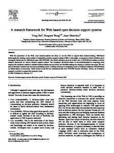
optimum with respect to the real world due to the inherent approximations in the model. However, this solution can be used to support a designer's quest for a superior solution. In a computer-assisted environment this support is provided in the form of optimal solutions for DSPs. Formulation and solution of DSPs provide a means for making the following types of decisions: • Selection - making a choice between a number of possibilities taking into account a number of measures of merit or attributes (Kuppuraju, Ittimakin et al. 1985; Mistree, Marinopoulos et al. 1988; Vadde, Allen et al. 1992). • Compromise - a primary DSP - the determination of the “right” values (or combination) of design variables to describe the best satisficing system design with respect to constraints and multiple goals (Mistree, Hughes et al. 1993) • Derived DSPs (see Figure 1) - a combination of primary DSPs to model a complex decision, e.g., selection/selection, compromise/compromise and selection/compromise decisions (Bascaran, Bannerot et al. 1989; Karandikar and Mistree 1991; Mistree, Smith et al. 1993; Vadde, Allen et al. 1994) Primary PrimaryDecisions Decisions Selection
Compromise
Derived Decisions: Dual Coupling
2. THE DECISION SUPPORT PROBLEM TECHNIQUE The DSP Technique consists of three principal components: a design philosophy rooted in systems thinking, an approach for identifying and formulating DSPs, and software. The DSP Technique requires that a designer implement two phases, namely, a meta-design phase and a computer-based design phase. Meta-design is accomplished through partitioning a problem into its elemental DSPs and then devising a plan of action (Mistree, Smith et al. 1990; Bras and Mistree 1991). Decision Support Problems provide a means for modeling decisions encountered in design and the domain specific mathematical models so built are called templates. Multiple objectives, quantified using analysis-based “hard” and insight-based “soft” information, can be modeled in DSPs (Mistree, Smith et al. 1990; Bras and Mistree 1991). For real-world, practical systems, all of the information for modeling systems comprehensively and accurately in the early stages of a project may not be available. Therefore, the solution to the problem, even if one is obtained using optimization techniques, cannot be
Compromise
Derived Decisions: Multiple Coupling Compromise
Compromise
Compromise
Selection
Selection
Selection
Figure 1: Primary & Derived Decisions (Karandikar and Mistree 1993) Selection and compromise Decision Support Problems may be solved in an environment in which uncertainty and risk are taken into consideration (Reddy and Mistree 1992; Zhou, Allen et al. 1992; Vadde, Krishnamachari et al. 1993; Allen 1996). Support is also provided for heuristic decisions which are made on the basis of a knowledge base of facts and rules of thumb; heuristic DSPs are solved using reasoning and logic only (Kamal 1990).
Based on Position Paper: Optimization in Decision-Based Design, DBD Workshop, Orlando, Florida, April 1997.
3. FUNDAMENTALS OF DECISION AND VALUE ANALYSIS Decisions in engineering design fall almost exclusively in the domain of making choice under conditions of uncertainty and risk. Necessary for this type of choice are three things: (1) options, (2) expectations, and (3) values. Options are the elements of the choice. A designer would, in a typically design situation, choose and option. An expectation comprises the range of possible outcomes of a decision paired with their probabilities of occurrence. Determination of expectations on each option is the realm of modeling (Hazelrigg 1996). Values are used in decision making to rank order alternatives. Similar to numerical optimization, we make use of a numerical function to rank order for two reasons: (1) it is too cumbersome to make an ad hoc assessment of the comparitive merits of all design alternatives, and (2) the comparison is generally too complex to make accurately and consistently without the use of a mathematical value. The mathematical requirements for preferences of a value function that rank orders all alternatives are stringent (Hazelrigg 1996). These mathematical conditions have been formalized by von-Neumann and Morgenstern in their axiomatic treatment of utility (von Neumann and Morgenstern 1947). What they showed is the following (Luce and Raiffa 1957): If a person is able to express preferences between every pair of gambles, where gambles are taken over some basic set of alternatives, then one can introduce utility associations to the basic alternatives in such a manner that, if the person is guided solely by the utility expected value, he/she is acting in accord with his/her true tastes – provided only that there is an element of consistency in his/her tastes. In the context of utility theory, a von NeumannMorgenstern lottery is shown in Figure 2. In this sense, the options are defined as A1, A2, … , Ar where without loss of generality we can assume that A1 f A2 f… f Ar. The circle represents a gamble, where A1 occurs with probability p1 and Ar occurs with probability 1- p1.
Outcome: status quo Decision to enter the lottery or remain at the status quo
More desired outcome, A1
Less desired outcome, Ar
Figure 2: A von Neumann-Morgenstern Lottery (Hazelrigg 1996) Using this notation but before introducing the axioms that provide the mathematical foundation for utility, the reader should keep the following interpretation of the axioms in mind (Luce and Raiffa 1957) Suppose that one has to make a choice between a pair of lotteries which are each composed of complicated alternatives. Because of their complexity it may be extremely difficult to decide which one is preferable [and this is usually the case in engineering design]. A natural procedure, then, is to analyze each lottery by decomposing it into simpler alternatives, to make decisions as to preference among these alternatives, and to agree upon some consistency rules which relate the simpler decisions to the more complicated ones. In this way, a consistent pattern is imposed upon the choices between complicated alternatives. This is fundamentally the notion of utility within engineering design, and the consistency rules are the vNM axioms which are as follows (Luce and Raiffa 1957; Hazelrigg 1996): 1. All outcomes of a vN-M lottery (options) can be ordered in terms of the decision maker’s preferences, and that ordering is transitive. 2. Any compound lottery, that is, any lottery that has an outcome another lottery, can be reduced to a simple lottery that has among its outcomes all the outcomes of the compound lottery with their associated probabilities of occurrence. 3. If the outcomes of a lottery, A1, A2, ..., Ar are ordered from most desired to least desired (respectively), then there exists a number u, such that one is indifferent between an outcome Ai , and [ui A1, (1-ui )Ar]. 4. For any lottery such as that given in axiom 3, with ui specified, there exists an outcome [ui A1, (1-ui )Ar] that can be substituted for Ai , and the preferences of the decision maker will remain unchanged. 5. The decision makers preferences and indifferences among lotteries are transitive.
Based on Position Paper: Optimization in Decision-Based Design, DBD Workshop, Orlando, Florida, April 1997.
6.
Given two lotteries, each with only two outcomes, and which differ only in terms of the probabilities of the outcomes, the lottery in which the probability of the more desired outcome is larger is the preferred lottery. These six axioms are the basis for decisions in utility theory. The formal theorem based on these axioms and the notation L = (p1A1, ... , prAr) and L′= (p1′ A1, ... , pr′ Ar) is as follows (Luce and Raiffa 1957): If the preference or indifference relation (f or ~) satisfies assumptions 1 through 6, there are numbers ui associated with the basic prizes Ai such that for two lotteries L and L′ the magnitudes of the expected values (p1u1 + p2u2 + … + prur) and (p1′ u1 + p2′ u2 + … + pr′ ur) reflect the preferences between the lotteries. The simple axioms above and their associated concepts for utility have been expressed in a framework for systems design by Hazelrigg (Hazelrigg 1996). The framework (see Figure 3) begins with an option set, S, consisting of all the configurations. Each configuration mi is represented by a parametric design vector, x. The components of x, xi, represent the system variables and are either continuous or discrete. The vector of design variables is a designers representation of the system. It is not useful for describing to a client the attributes of a product. For example, in designing a car, a system variable, xi, may be the compression ratio in the engine. Consumers, however, are rarely concerned with this variable and are more concerned with the attributes of a particular system configuration. Thus, we change the design variables into a vector of system attributes, a, that are recognizable to E{u}m a x | p (t ),
consumers. The design variables and the attributes in general will not have a 1 to 1 correspondence. In addition we need to represent the uncertainty in x and the noise variables in the system. This is done by introducing a vector of exogenous variables, y. The exogenous variables affect, the particular vector of attributes, a. Thus, the system attributes are characterized as ay, that is the vector a subject to the vector of exogenous variables, y. After the configuration is represented in terms of attributes, we have a valid input to a demand function, which in turn, gives us the expected revenue of the particular configuration. Here we see a deviation from the way in which we typically evaluate a design. Instead of measuring the design on some compound scale, we are concerned primarily with the expected revenue of the system, which is a function of the price, time (for the time-value of money) and the attributes. This addition is the entire expected revenue of configuration mi as a function of time. For the purposes of finding the utility of a design configuration, expected revenue represents only half of the relation, with expected cost completing the relation. In terms of this design framework, we are concerned with establishing the Net Present Value (NPV) of a design option where NPV is given by ∞
NPV = ∫e − rt (Re v(t) − Cost(t))dt
(1)
0
where r is the discount rate (estimated) and t is time. Note, that the costs associated with configuration mi have
x Ch o o s e x t o m a x E{u }
E{u }m a x | p ( t )
Cho o s e p (t ) t o m a x E{u (NPV)} p (t )
Co n f ig u r a t io n m i
Pa r a m e t r ic De s ig n Ve c t o r x
Sy s t e m At t r ib u t e s a y
De m a n d q (a y ,p ,t )
Exp ec Rev ted enu e(t)
+ s (m ) Ex o g e n o u s
Va r ia b le s y
Ma n uf a c t u r in g Co s t s c m (t , y , x )
Ot h e r Co s t s Σc i(t ,y , x)
NP V
Ex p e c t e d Ut ilit y E{u ( NP V) }
d cte pe Ex st(t) o C
Figure 3: A Framework for Decision-Based Design (Hazelrigg 1996)
Based on Position Paper: Optimization in Decision-Based Design, DBD Workshop, Orlando, Florida, April 1997.
not been explicitly accounted for. These costs consist of the normal entities we would associate with design and manufacture of a product including labor, machines, materials, disposal, etc. In addition, we associate life cycle issues as a cost associated with configuration mi. These costs are subject to the same uncertainty as the configuration itself. The astute reader may notice that calculation of demand requires knowledge of the elasticity of demand and therefore price as a function of time, p(t). Using the customers utility for money, we can perform an optimization to maximize utility with respect to p(t), a variable under our control.
rigorously address the following four areas of subjectivity: 1. Subjectivity in the creation of options and size of the option set. 2. In the development of expectations, which phenomenon to include and/or exclude. This has two separate components: a) The assignment of probabilities or b) determination of insignificance of effect. 3. The assignment of uncertainty to system variables. 4. Subjectivity in designer preferences. By addressing these four areas explicitly within the DSP Technique, we believe that the utility theory framework for systems design can be integrated with the DSP Technique. These four areas of subjectivity are shown in Figure 5.
This simple maximization is a subset of the more general maximization of expected utility. By changing the design vector, x, we can optimize the design with respect to our expected utility. Note that the chain of computations required here is extensive; it is unlikely that the average workstation could solve these optimizations in a reasonable amount of time. The entire framework is shown in Figure 3.
.
1
Motor 1
Motor 2 0 Preference (left is preferred to right)
The DSP Technique
uncertainty in system variables subjectivity in developing expectations
Figure 5: The Means to Integrate the DSP Technique and a Utility Theory Framework for Systems Design In Figure 5, the four areas of subjectivity are shown as ‘wrecking balls’ready to break down the barrier between the DSP Technique and the utility theory framework for systems design. By explicitly addressing the four areas, we believe that the six axioms of utility theory can be modified to include the four areas of subjectivity in a comprehensive framework for systems design. In the next section, we begin addressing the areas explicitly,
Probability of Preferring Motor
Probability of Preferring Motor
4. IDENTIFYING THE TASKS AND INTELLECTUAL NEEDS FOR THE FRAMEWORK: SWITCHING FROM OPTIMIZING TO SATISFICING Within the framework in Figure 3, there exists a need to
the creation of options
The utility theory framework for systems design
The use of this framework for system level design is subject to computational limitations. In addition, this framework lacks four areas of subjectivity that must be explicitly addressed in engineering design. These are important identifications, for they lead us from the realm of optimizing as given in the framework to the realm of satisficing based on the information-theoretic limitations of real-world design.
subjectivity in preferences
Motor 1
Motor 2
Preference (left is preferred to right)
(a) vN-M utility theory (b) probabilistic utility theory Figure 4: vN-M and Probabilistic Preferences
Based on Position Paper: Optimization in Decision-Based Design, DBD Workshop, Orlando, Florida, April 1997.
and falls within the realm of scientific assessment of uncertainty.
revealing planned research and ongoing tasks. 4.1 Subjectivity
in
Preferences
and
in
Developing Expectations These two areas of subjectivity are included together here because it is not entirely clear that the two are independent of one another. Utility theory as formulated by von Neumann and Morgenstern has as two basic principles (1) that given two alternatives a person either prefers one to the other or is indifferent between them and (2) that probabilities that are manipulated according to the rules of calculus and can be assigned to certain chance events (Luce and Raiffa 1957). In engineering design, uncertainty generated by probabilistic preferences that is carried through models to the establishment of probabilities for events relegates this second assumption fallacious. Thus, the first assumption needs to account for probabilistic preferences. For example, if asked to choose between two motors for a design, we may have a preference structure as shown in Figure 4. In Figure 4a, the person always prefers Motor 1 to Motor 2. But this may not always be the case. In Figure 4b, we assign probability distribution functions to preferences for prizes, so that the person usually prefers Motor 1 to Motor 2, but may on occasion choose Motor 2 over Motor 1. Luce has presented a probabilistic theory of utility in which people are assumed to have probabilistic preferences and in which people cannot perfectly discriminate between events (Luce and Raiffa 1957). With the inclusion of these two areas of subjectivity in the DSP Technique and in utility theory, we have identified a means of breaking down part of the ‘intellectual’ wall in Figure 5. Note that the DSP Technique has been used extensively in probabilistic environments (Reddy and Mistree 1992; Zhou, Allen et al. 1992; Vadde, Krishnamachari et al. 1993; Allen 1996).
esoy e h t Tdewili s t amu em stfr sy
subjectivity in preferences the creation of options
T h e D S P T ec h n iq ue
uncertainty in system variables
4.2 Uncertainty in System Variables In the utility theory framework of Figure 3, a vector of exogenous variables represents not only noise factors in the system, but the uncertainties associated with the system variables themselves, xi. In the majority of engineering practice, the assignment of uncertainty is either stochastic or arbitrary. It is the latter practice that concerns us in the utility theory framework. Hazelrigg (Hazelrigg 1996) has shown that failure to include uncertainty in even the most simple relationships, F=ma for example, leads to nonsensical results. It is our contention that the inclusion of arbitrary uncertainty, in the form of assumed probability distributions, is similarly nonsensical. If we must include uncertainty, then the assumed joint distribution on system variables should be assigned in such a way that we make no assumptions other than what the information we have leads us to. There is a well known method for assigning uncertainty to system variables based on the principle of informationtheoretic entropy optimization (Kapur and Kesavan 1992). The fundamental premise in information-theoretic entropy optimization is this (Kapur and Kesavan 1992): Out of all probability distributions consistent with a given set of constraints, choose the one that has maximum uncertainty. This principle is based on the notion that while we are trying to reduce uncertainty, assigning distributions that do not account for all uncertainty inherent in the system is fallacious. It is important to realize that probabilistic uncertainty and information-theoretic entropy are synonyms in this context. The actual mathematics of entropy maximization are not presented here, but are well documented (Jaynes 1957; Kullback 1959; Kapur and Kesavan 1992). The inclusion of entropy optimization in the DSP Technique provides a mathematically rigorous way of assigning uncertainty to system variables and provides the necessary method for swinging the uncertainty ball towards the now probabilistic utility theory framework in Figure 7.
subjectivity in developing expectations
The "Intellectual" Wall
Figure 6: Subjectivity in Preferences and Expectations This extension to classical utility theory involves the assignment of probabilities based on limited information,
Based on Position Paper: Optimization in Decision-Based Design, DBD Workshop, Orlando, Florida, April 1997.
The DSP Technique
the creation of options
uncertainty in system variables
subjectivity in developing expectations
The probabilistic utility theory framework for systems design
subjectivity in preferences
formalized in (Mistree, Smith et al. 1990; Bras and Mistree 1991).
subjectivity in preferences
In Figure 7, the probabilistic theory of utility now includes a scientific method for assigning uncertainty to the system variables. What remains to be included in the probabilistic utility theory framework is method for option generation. Recall that the framework in Figure 3 assumes that we have an option set S from which to make our comparisons. Actually generating the option set is an important part of a design process and any framework for systems design. 4.3 The Generation of Options Subjectivity in the generation of options within the context of utility theory has essentially two parts: (1) when to stop generating options and (2) which options to include in the option set, S. Although option generation is largely a creative endeavor (Cross, Naughton et al. 1980), formalizing the process by which options are generated is an important step in producing an encompassing framework for systems design. In designing for concept within the DSP Technique, we seek to cast as wide a net as possible and then to home in systematically on concepts to include in the option set. Methods for actually generating concepts within the DSP Technique can be found in (Mistree, Muster et al. 1990). Note that we have not explicitly defined rules for when to stop generation options, but we have made provision for which options to include in the option set, S. Option generation is the final area of subjectivity that needs to be addressed in the utility theory framework. In Figure 8, we show that the wall between the utility theory framework and the DSP Technique is broken. Our next step is to formally model the framework in terms of the DSP Technique Palette. In addition, the DSP Technique framework chosen includes the four areas of subjectivity as mathematical formalisms not explicitly addressed in the utility theory framework. Examples of DSPs that include uncertainty and risk can be found in (Reddy and Mistree 1992; Zhou, Allen et al. 1992; Vadde, Krishnamachari et al. 1993; Allen 1996). Option generation, under the auspices of designing for concept is
T h e D S P T ec h n iq ue
Figure 7: Probabilistic Utility Theory with Scientific Assignment of Uncertainty
e sdew h Tm m era stf sy
the creation of options uncertainty in system variables
The "Intellectual" Wall
subjectivity in developing expectations
Figure 8: The ‘Breaking’of the Wall
5. MODELING THE FRAMEWORK FOR SYSTEMS DESIGN WITH THE DSP TECHNIQUE PALETTE In the DBD paradigm the role of optimization is to support human judgment not replace it. Our focus therefore is to share our observations with respect to modeling such support for human decision making from the perspective of an optimizer and that of a satisficer. Let us explain. Consider a haystack with a number of needles hidden in it. An optimizer will continue searching the haystack until the last needle has been found. A satisficer, on the other hand, stops when he/she had found enough needles to proceed to the next step. We can capture the perspective of the optimizer by using the single objective optimization model and we can capture the perspective of the satisficer by using the compromise DSP. We view the framework in Figure 3 as unable to represent a general design process. Thus, we brought to light four areas of subjectivity not explicitly accounted by that framework. By modifying the framework and representing it as a hierarchy within the DSP Technique, the inclusion of these areas of subjectivity is facilitated. In representing the utility theory framework for systems design, we need simply convert those entities in Figure 3 to their equivalent mathematical form in the DSP Technique Palette (Mistree, Smith et al. 1990; Bras and Mistree 1991).
Based on Position Paper: Optimization in Decision-Based Design, DBD Workshop, Orlando, Florida, April 1997.
5.1 The DSP Technique Palette The DSP Technique Palette contains the entities for modeling processes. These entities are used to build hierarchies and model design processes independent of the domain of application. The DSP Technique Palette contains three different classes of entities, namely, Potential Support Problem entities, Base entities and Transmission entities (see Figure 9). DSPT Palette Entities
Potential Base Transmission Support Problem Entities Entities Entities Figure 9: DSPT Palette Entity Classes (Bras and Mistree 1991)
The most complex entities in the DSP Technique Palette are the Potential Support Problem entities, being phases, events, tasks, decisions and systems. The icons for these entities are shown in Figure 10.
P
Phase
E
Event
T
Task
?
Decision... System
?
Compromise Decision
?
Selection Decision
?
Preliminary Selection Decision
?
Heuristic Decision
Figure 10: Potential Support Problem Entities (Bras and Mistree 1991) The phase icon is identified by a “P” and is used to represent pieces of a partitioned process. Events occur within a phase and the event icon is identified by an “E”. Tasks and decisions are used to model phases and events.
Tasks and decisions require direct involvement of human designers and/or systems. This, in contrast with phases and events on which human designers do not have direct influence. Phases and events are accomplished by performing tasks and making decisions. A task is an activity to be accomplished. In our palette a task is identified by a “T” (Mistree, Smith et al. 1990; Bras and Mistree 1991). A decision icon is defined by a rectangle with a question mark within it. This choice is natural as a question mark often implies a decision. Currently we have included the compromise, selection, preliminary selection and heuristic decisions in the palette. Selection is a converging activity since the number of alternatives is reduced. The icons for both selection and preliminary selection characterize this in our palette. The selection decision icon has a single point, indicating that on solving a selection decision a single alternative is identified for further development. The preliminary selection icon is similar but it does not end with a point indicating that on making a preliminary selection decision a number of most-likely-to-succeed concepts are identified for further development. The icon for a compromise decision ends in a “C”. A compromise represents a trade-off between conflicting goals. When there is no conflict between the goals the solution could be represented by the upper or lower extremes of the C in the rectangle. However, when there is a conflict, which invariably is the case, the result emerges from the middle; it represents a compromise between two extremes (Mistree, Smith et al. 1990; Bras and Mistree 1991). A system can be either concrete (e.g., a ship, an airplane) or abstract (e.g., a company’s organization) and can be modeled by a grouping of associated subsystems. Accordingly, a process is a system as are, potentially, the higher-level entities used to model the process. A system is identified by a circle with a smaller circle in the middle. This illustrates the central nature of a system in the process. The fact that other systems and their associated information are embedded in the system is symbolized by the small circle. Base entities are the most elementary entities for modeling design processes. Base entities are implementable on a computer and/or easy to understand by designers. The icons for the Base entities and detailed descriptions can be found in (Bras and Mistree 1991). In our work we have been influenced by Miller’s Living Systems Theory (Miller 1978). Like Miller, we use Transmission entities to achieve the connections between
Based on Position Paper: Optimization in Decision-Based Design, DBD Workshop, Orlando, Florida, April 1997.
the aforementioned entities. With the exception of system variables and scalar auxiliary parameters all entities require an input and provide some output. The Transmission entities capture these inputs and outputs. Like Miller and others (e.g., (Hubka 1982; Roth 1982; Pahl and Beitz 1988)) we distinguish three types of transmissions, namely, information, energy, matter, and combinations of these three basic transmissions. Our icons for the Transmission entities are shown in Figure 11. A Transmission entity usually embeds a list of other DSP Technique Palette entities that are transmitted from one entity to another. For instance the task “Provide the goals and constraints” would have an information Transmission entity as output embodying a list of constraint and goal entities representing the specific output of the task.
i
Information
5.2 Modeling the Expected Utility Framework as a Hierarchy With the DSP Technique Palette In this section we show how the framework in Figure 3 is included in the DSP Technique, and we extend the framework by including, on a conceptual level, the four areas of subjectivity identified previously. We model the framework as a conceptual design phase that translates customer needs into knowledge about a product through events, tasks, and decisions. In Figure 12, we show a design timeline that includes the conceptual design phase (the first P icon in Figure 12.) Within the conceptual design phase (the dotted lines) is a model of the events and information included. In a GUI, we simply click on the designing for concept phase to expand the events within. The conceptual design event within Figure 12 is shown expanded in Figure 13.
Energy Matter
i
Information+ Energy
i
Information+ Matter
Customer Strategic Need
i
i
Figure 11: Transmission Entities (Bras and Mistree 1991) BUILDING PROCESS NETWORKS - A uniform representation scheme for the DSPT Palette entities is developed by recognizing that all entities, with the exception of system variables, scalar auxiliary parameters (a multi-dimensional parameter which requires indices as input) and Transmission entities convert some input into an output. In the context of our definition of designing, these entities convert information into knowledge. Thus, in their most abstract form these entities are relationships with an input and an output. This view facilitates the combination of different types of entities into networks, that is, into hierarchies. These hierarchies represent the information and knowledge held and generated at different levels of complexity. An example of this is the combination of subroutines into a FORTRAN program (Mistree, Smith et al. 1990; Bras and Mistree 1991).
P
P
P
i
Total Life Cycle Design Knowledge
DESIGNING FOR CONCEPT Concept(s) Information
Energy+ Matter Information+ Energy+ Matter
P
i Functional Requirements (FRs)
Customer Strategic Need i
E Development of FRs
i
Preliminary Design
E
i
Basic Conceptual Concept Design
E
i
Robust Top Level Specification
i
Expected Utility
i
General Specification
E
Embodiment Design
i General Design Knowledge
Figure 12: A Model of Designing for Concept (Adapted from (Mistree, Smith et al. 1990))
Based on Position Paper: Optimization in Decision-Based Design, DBD Workshop, Orlando, Florida, April 1997.
Conceptual Design E
•The vector of system variables, x
Basic Concept
• The price, p(t)
i
•The vector of deviation variables (di-, di+) Determine Demand
Exogenous Variables
i
T Utility of NPV
Determine System Attributes
T
i
i
T
?
i
Measure of Demand
Suitable Concepts Concepts
i
?
Generate Concepts
i
?
E{u}
Concept Parameterization
T
i
i Basic Concept
Measure of Costs
Satisfy • the bounds on the system variables, x: xmin = x = xmax • di- , di+ = 0 and •di- . di+ = 0 • the E{u}: E{u}/ ET{u} - 1.0 + d1- - d1+ = 0.0 Minimize the deviation function; Z = [ f1( d-, d+ ), ... , fk( d-, d+ ) ].
Box 1: The Utility Theory Framework Compromise DSP i
T
General Design Knowledge
Determine Costs
Figure 13: An Expected Utility Framework for Conceptual Design In Figure 13 we show the expected utility framework in terms of DSPs, information, and tasks. Included in this model is the generation of options and entropy optimization. Note that in this framework, finding p(t) and E{u} of a concept are performed in a single compromise DSP, while selection of the basic concept occurs subsequent to this activity. Thus, in the DSP model of Figure 13, we facilitate concurrency by representing entropy optimization, determination of p(t) and E{u} as a single compromise DSP. In addition, the the sense that the decision framework of Figure 3 represents only one event in a hierarchy of phases and a network of events is shown in Figure 12 and Figure 13. In Figure 13, the compromise DSP is indicated by the circle. By clicking on this icon in a GUI, we get the mathematical formulation shown in Box 1. Given • a design configuration mi, • a vector of exogenous variables y • a transformation function Ta( ) that transforms x and y into ay; ay = Ta(x, y) • a transformation function Tq( ) that calculates demand, q = Tq(ay, p, t), p is price, t is time • a transformation function Tc( ) that calculates manufacturing costs, cm = Tc(t, y, x) • a set of transformation functions {Toci( )} that calculates other costs, co = ΣToci(t, x, y) • a utility function on Net Present Value u(NPV) • Shannon’s measure of entropy • a target E{u}, ET{u} Find
In this compromise DSP we note several things. The goal programming model and the compromise DSP are the same in this case since there are no constraints, other than those on the entropy in the system, i.e., Σpi=1, etc. Entropy, p(t) and E{u} are determined in a single DSP, rather than sequentially as in the framework of Figure 3. Why is this representation beneficial? In formulating the utility theory framework as a process we note several things. The entire framework represents a hierarchy of concurrent decisions, not the sequential series of decisions as in Figure 3. In addition, the palette formulation gives us a sense for the amount of information needed to implement this framework. Obviously neither form is readily implementable on a computer, although in the DSP Technique network of entities we can readily include the four areas of subjectivity identified as necessary for human decision making. Thus, we have identified and formulated a new model of designing that inludes expected utility theory and the inherent subjectivity in design as a hierarchy within the DSP Technique. 6. CLOSURE What has been shown in this paper? We have shown that utility theory forms the foundation of any implementation of DBD. In particular, we restated the six vN-M axioms as axioms for deterministic decision making. We then showed a framework for systems design in which utility theory is used correctly (Hazelrigg 1996). The framework, however, lacks at least four areas of subjectivity that must be accounted for in design: 1. Subjectivity in the creation of options and size of the option set. 2. In the development of expectations, which phenomenon to include and/or exclude. This has two separate components:
Based on Position Paper: Optimization in Decision-Based Design, DBD Workshop, Orlando, Florida, April 1997.
a) The assignment of probabilities or b) determination of insignificance of effect. 3. The assignment of uncertainty to system variables. 4. Subjectivity in designer preferences. These areas of subjectivity are individually addressed as areas of future research. We note in particular the need for scientific assessment of probabilities, something distinctly lacking in both the DSP Technique and Hazelrigg’s framework. We then showed how the DSP Technique is used to incorporate utility theory in the context of systems design. This hierarchical representation of Hazelrigg’s framework is ongoing research. In the realm of DBD, we have become accustomed to assuming that designers are performing design correctly. Thus, a large portion of engineering design research has focused on developing descriptive models of a design process. Hazelrigg has taken an old idea and enlightened those of us who have forgotten that if designing is decision making, then rationality and utility theory are the basis for any description or model of a design process. We have taken this issue to heart in formulating a model of expected utility theory within the DSP Technique. 7. ACKNOWLEDGMENTS We gratefully acknowledge support from NSF Grant DMI 9612327. Matthew Marston is funded by a NSF Graduate Research Fellowship. 8. REFERENCES Allen, J. K. (1996) The Decision to Introduce New Technology: The Fuzzy Preliminary Selection Decision Support Problem, Engineering Optimization, 26(1), 6177. Bascaran, E., Bannerot, R. B. and Mistree, F. (1989) Hierarchical Selection Decision Support Problems in Conceptual Design, Engineering Optimization, 14, 207-238. Bras, B. A. and Mistree, F. (1991) Designing Design Processes in Decision-Based Concurrent Engineering in SAE Transactions, Journal of Materials & Manufacturing, SAE International, Warrendale, Pennsylvania, 451-458. Cross, N., Naughton, J. and Walker, D. (1980) Design Method and Scientific Method, Design; Science; Method, R. Jacques and J. A. Powell, Proceedings of the 1980 Design Research Society Conference, Westbury House, 18-29. Hazelrigg, G. A. (1996) Systems Engineering: An Approach to Information-Based Design, Prentice Hall, Upper Saddle River, N.J.
Hubka, V. (1982) Principles of Engineering Design, Butterworth & Co. (Publishers) Ltd., London. Jaynes, E. T. (1957) Information Theory and Statistical Mechanics, Physical Reviews, 106, 620-630. Kamal, S. Z. (1990) The Development of Heuristic Decision Support Problems for Adaptive Design, Ph.D. Dissertation, Department of Mechanical Engineering, University of Houston, Houston, Texas. Kapur, J. N. and Kesavan, H. K. (1992) Entropy Optimization Principles with Applications, Academic Press, Inc., New York. Karandikar, H. M. and Mistree, F. (1991) Modeling Concurrency in the Design of Composite Structures in Structural Optimization: Status and Promise, M. P. Kamat, AIAA, Washington, D.C., 769-806. Karandikar, H. M. and Mistree, F. (1993) Modeling Concurrency in the jDesign of Composite Structures in Structural Optimization: Status and Promise, M. P. Kamat, AIAA, Washington, D.C., 247-286. Kullback, S. (1959) Information Theory and Statistics, John Wiley, New York. Kuppuraju, N., Ittimakin, P. and Mistree, F. (1985) Design through Selection ... A Method that Works, Design Studies, 6(2), 91-106. Luce, R. D. and Raiffa, H. (1957) Games and Decisions, John Wiley and Sons, Inc., New York. Miller, J. G. (1978) Living Systems, McGraw-Hill Book Company, New York. Mistree, F., Hughes, O. F. and Bras, B. A. (1993) The Compromise Decision Support Problem and the Adaptive Linear Programming Algorithm in Structural Optimization: Status and Promise, M. P. Kamat, AIAA, Washington, D.C., 247-289. Mistree, F., Marinopoulos, S., Jackson, D. and Shupe, J. A. (1988) The Design of Aircraft using the Decision Support Problem Technique, NASA Contractor Report 4134. Mistree, F., Muster, D., Srinivasan, S. and Mudali, S. (1990) Design of Linkages: A Conceptual Exercise in Designing for Concept, Mech. Mach. Theory, 25(3), 273-286. Mistree, F., Smith, W. and Bras, B. (1993) A DecisionBased Approach to Concurrent Engineering in Handbook of Concurrent Engineering, H. Paresai and W. Sullivan, Chapman & Hall, New York, New York, 127-158. Mistree, F., Smith, W. F., Bras, B., Allen, J. K. and Muster, D. (1990) Decision-Based Design: A Contemporary Paradigm for Ship Design in Transactions, Society of Naval Architects and Marine Engineers, Jersey City, New Jersey, 565-597. Pahl, G. and Beitz, W. (1988) Engineering Design, The Design Council/Springer-Verlag, London/Berlin.
Based on Position Paper: Optimization in Decision-Based Design, DBD Workshop, Orlando, Florida, April 1997.
Reddy, R. and Mistree, F. (1992) Modeling Uncertainty in Selection using Exact Interval Arithmetic in Design Theory and Methodology 92, L. A. Stauffer and D. L. Taylor, ASME, New York, 193-201. Roth, K. (1982) Konstruieren mit Konstruktionskatalogen, Springer-Verlag, Berlin. Shupe, J. A. (1988) Decision-Based Design: Taxonomy and Implementation, Ph.D. Dissertation, Department of Mechanical Engineering, University of Houston, Houston, Texas. Simon, H. A. (1996) The Sciences of the Artificial, The MIT Press, Cambridge, Mass. Vadde, S., Allen, J. K. and Mistree, F. (1992) Catalog Design: Design Using Available Assets in Advances in Design Automation, D. A. Hoeltzel, ASME, New York, 345-354. Vadde, S., Allen, J. K. and Mistree, F. (1994) Compromise Decision Support Problems for Hierarchical Design Involving Uncertainty, Computers and Structures, 52(4), 645-658. Vadde, S., Krishnamachari, R. S., Allen, J. K. and Mistree, F. (1993) The Bayesian Compromise Decision Support Problem for Hierarchical Design Involving Uncertainty, ASME Journal of Mechanical Design, 116, 388-395. von Neumann, J. and Morgenstern, O. (1947) The Theory of Games and Economic Behavior, Princeton University Press, Princeton, NJ. Zhou, Q.-J., Allen, J. K. and Mistree, F. (1992) Decisions Under Uncertainty: The Fuzzy Compromise Decision Support Problem, Engineering Optimization, 20, 21-43.
Based on Position Paper: Optimization in Decision-Based Design, DBD Workshop, Orlando, Florida, April 1997.